1997 MERCEDES-BENZ ML320 turn signal
[x] Cancel search: turn signalPage 1757 of 4133
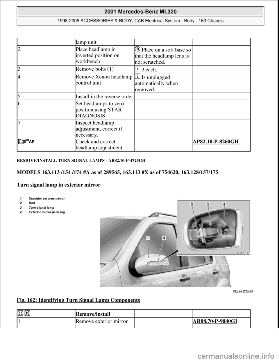
REMOVE/INSTALL TURN SIGNAL LAMPS - AR82.10-P-4725GH
MODELS 163.113 /154 /174 #A as of 289565, 163.113 #X as of 754620, 163.128/157/175
Turn signal lamp in exterior mirror
Fig. 162: Identifying Turn Signal Lamp Components
lamp unit
2Place headlamp in
inverted position on
workbenchPlace on a soft base so
that the headlamp lens is
not scratched.
3Remove bolts (1) 3 each.
4Remove Xenon headlamp
control unit Is unplugged
automatically when
removed.
5Install in the reverse order
6Set headlamps to zero
position using STAR
DIAGNOSIS
7Inspect headlamp
adjustment, correct if
necessary.
Check and correct
headlamp adjustment AP82.10-P-8260GH
Remove/install
1Remove exterior mirror AR88.70-P-9040GI
2001 Mercedes-Benz ML320
1998-2005 ACCESSORIES & BODY, CAB Electrical System - Body - 163 Chassis
me
Saturday, October 02, 2010 3:30:09 PMPage 262 © 2006 Mitchell Repair Information Company, LLC.
Page 1758 of 4133
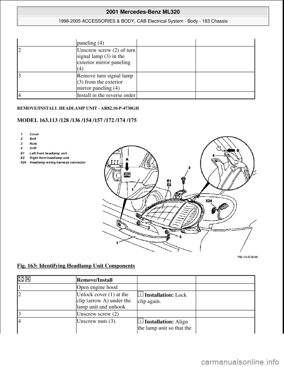
REMOVE/INSTALL HEADLAMP UNIT - AR82.10-P-4730GH
MODEL 163.113 /128 /136 /154 /157 /172 /174 /175
Fig. 163: Identifying Headlamp Unit Components
paneling (4)
2Unscrew screw (2) of turn
signal lamp (3) in the
exterior mirror paneling
(4)
3Remove turn signal lamp
(3) from the exterior
mirror paneling (4)
4Install in the reverse order
Remove/Install
1Open engine hood
2Unlock cover (1) at the
clip (arrow A) under the
lamp unit and unhook Installation: Lock
clip again.
3Unscrew screw (2)
4Unscrew nuts (3). Installation: Align
the lamp unit so that the
2001 Mercedes-Benz ML320
1998-2005 ACCESSORIES & BODY, CAB Electrical System - Body - 163 Chassis
me
Saturday, October 02, 2010 3:30:09 PMPage 263 © 2006 Mitchell Repair Information Company, LLC.
Page 1830 of 4133
5Navigation menuCall up navigation menu by
pressing NAV buttonLANGUAGE POS
TIME WHEEL
6Erase initial calibration Applies only if unit has
been calibrated initially.
By turning on the right
control knob (10) select
menu "ENTER
ADDRESS" and confirm
by pressing control knob
(10).
Press multifunction key 2,
then 7 and release
simultaneousl
y. Press CAL
multifunction key.
CAL
By turning the right control
knob (10) select menu
"ERASE CALIBRATION"
and confirm by pressing the
control knob (10).After a certain waiting
time the basic
navigation menu
appears
7Start-upPark vehicle outside with
Audio 30 APS switched on
(minimum time for receiving
GPS satellite signals approx.
30 min.).
Call up navigation menu by
pressing NAV buttonLANGUAGE POS
TIME WHEEL
8Select languageSelect desired language by
pressing the multifunction
key "SPRA"
9Enter tire sizeEnter the tire size by
pressing the multifunction
key "WHEEL" and confirm
by pressing the right control
knob (10)
10Perform calibration
drive The duration of the
calibration drive depends on
the vehicle model and
number of changes in
direction. It can be between
30 km and 100 km and can
be interrupted at any time
for as long as desired.
Drive Audio 30 APS at least
300 meters straight ahead in
the radio mode and then turn
correctly to the right or left
2001 Mercedes-Benz ML320
1998-2005 ACCESSORIES & BODY, CAB Electrical System - Body - 163 Chassis
me
Saturday, October 02, 2010 3:30:11 PMPage 335 © 2006 Mitchell Repair Information Company, LLC.
Page 2139 of 4133

GF54.21-P-4106-01GH
Extended Activity Module - Task
n
The primary tasks of the Extended Activity Module (EAM, N10/1) are
as follows:
D
To control the door sill lights
D
To suppress the auto-dimming mirror function
D
To control the headlight cleaning system (HCS)
D
To control the rear window defroster
D
To control seat heating
D
To control the power supply via control console to tilt/sliding or
louvered sunroof switch
D
To control the PTC heater booster (R22/3)
D
To control the auxiliary fan (M4)
D
To read the cruise control switch (S40) and relay data to control
module (DAS, N73/1)
D
To read the contacts for wiper speed settings 1 and 2 on
combination switch (S4) for diagnosis.
To perform these tasks the Extended Activity Module (EAM, N10/1)
reads various signals and switch settings directly.
The Extended Activity Module (EAM, N10/1) interfaces with other
control modules via the engine compartment CAN.
-----------------------------------------------------------------------------------------
Diagnosis
Diagnosis is performed using the Star diagnostic tool. To facilitate
this task, the Extended Activity Module (EAM, N10/1) is equipped
with its own diagnostics cable.
This cable is also used to diagnose the
All Activity Module (AAM,
N10)
and the
transfer case control module (N78)
.
The Extended Activity Module (EAM, N10/1) is linked to the All
Activity Module (AAM, N10) via the
engine compartment CAN
.
Data communication between the All Activity Module (AAM,
N10) and the Extended Activity Module (EAM, N10/1) is
assumed by the
CAN (N10 - N10/1)
when terminal 15 is off.
The CAN (N10 - N10/1)
is an independent CAN bus located
between the All Activity Module (AAM, N10) and the Extended
Activity Module (EAM, N10/1).
No other
control modules are
connected to the CAN (N10 - N10/1).
-----------------------------------------------------------------------------------------
Details:
Door sill lights
When the front interior light is on and one of the front doors is open,
or when the rear interior light is on and one of the back doors is open,
the door sill lights for the open door will illuminate.
Headlight cleaning system (HCS)
Activating a separate switch causes the EAM to send a turn-on signal
to the HCS pump relay.
EAM will send an additional turn-on signal to the HCS pump relay
only after the cleaning operation is completed and a "rest period" of
approximately 2.5 sec. has passed.
Auto-dimming mirror function
The auto-dimming mirror function is suppressed when the interior
light is on or reverse gear is engaged.
Auto-dimming suppression for the outside rearview mirror (slave) is
activated by the inside rearview mirror (master).
Heater booster/PTC air heater for diesel engines
EAM monitors system voltage and adjusts heater booster capacity to
minimize load on battery.
Rear window defroster
EAM sets maximum ON time for rear window defroster depending
on outdoor temperature and current vehicle speed.
D
Standard ON time:
10 min.
D
Outdoor temperature < 5
o
C:
Additional 5 min.
D
Speed >80 km/h:
Additional 3 min.
Seat heating
Sets maximum seat heating time.
D
Setting 1: max. 20 min.
D
Setting 2: max. 5 min.
Tilt/sliding or louvered sunroofs
Signal via AAM2 allows operation of tilt/sliding or louvered sunroofs
when ignition is on (standard mode) or off (keyless mode).
Ignition authorization via CAN
The EAM issues ignition authorization to AAM2 via the engine
compartment CAN depending on the requirements of the engine
control unit in connection with the FBM.
Copyright DaimlerChrysler AG 18.05.2006 CD-Ausgabe G/10/04 . This WIS print-out will not be recorde
d by Modification services.
Page 1
Page 2142 of 4133
CIRCUIT PROTECTION DEVICES
CIRCUIT PROTECTION DEVICES LOCATION
box.
Fuel Pump RelayIn left side of engine compartment, in fuse & relay
box.
Headlamp Cleaning System RelayIn right front footwell fuse & relay box.
Heated Rear Window RelayIn right front footwell fuse & relay box.
Heater RelayAt right kick panel.
Heater Relay (Stage 1)At right kick panel.
Heater Relay (Stage 2)At right kick panel.
High Pressure/Return Pump RelayIn left side of engine compartment, in fuse & relay
box.
Left Front Power Window RelayIn left side of engine compartment, in fuse & relay
box.
Left Turn Signal RelayIn left side of engine compartment, in fuse & relay
box.
Low Beam Headlamp Relay (W/ DRL)In left side of engine compartment, in fuse & relay
box.
Rear Foglight RelayIn left side of engine compartment, in fuse & relay
box.
Rear Wall Door Washer Pump RelayIn left side of engine compartment, in fuse & relay
box.
Rear Window Defroster RelayIn right front footwell fuse & relay box.
Right Front Power Window RelayIn left side of engine compartment, in fuse & relay
box.
Right Turn Signal RelayIn left side of engine compartment, in fuse & relay
box.
Seat Comfort RelayIn right front footwell fuse & relay box.
Seat Heater Relay (Stage 1)On underside of left/right front seat.
Seat Heater Relay (Stage 2)On underside of left/right front seat.
Secondary Air Injection Pump RelayIn left side of engine compartment, in fuse & relay
box.
Starter RelayIn left side of engine compartment, in fuse & relay
box.
Two-Tone Horn RelayIn left side of engine compartment, in fuse & relay
box.
ComponentComponent Location
E-BoxIn left side of engine compartment.
Fuse & Relay BoxIn left side of engine compartment, in E-box. See
Fig. 1
.
Right Front Footwell Fuse & Relay BoxBelow right side of dash, behind kick panel. See
2001 Mercedes-Benz ML320
2001 MERCEDES-BENZ ML320 & ML430
me
Saturday, October 02, 2010 3:21:17 PMPage 2 © 2006 Mitchell Repair Information Company, LLC.
Page 2143 of 4133
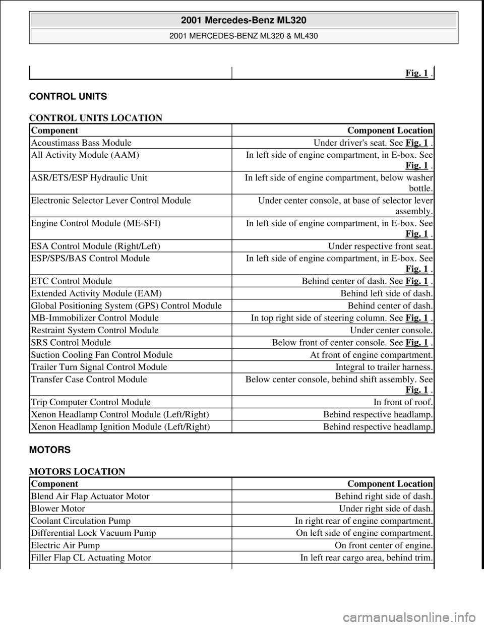
CONTROL UNITS
CONTROL UNITS LOCATION
MOTORS
MOTORS LOCATION
Fig. 1 .
ComponentComponent Location
Acoustimass Bass ModuleUnder driver's seat. See Fig. 1 .
All Activity Module (AAM)In left side of engine compartment, in E-box. See
Fig. 1
.
ASR/ETS/ESP Hydraulic UnitIn left side of engine compartment, below washer
bottle.
Electronic Selector Lever Control ModuleUnder center console, at base of selector lever
assembly.
Engine Control Module (ME-SFI)In left side of engine compartment, in E-box. See
Fig. 1
.
ESA Control Module (Right/Left)Under respective front seat.
ESP/SPS/BAS Control ModuleIn left side of engine compartment, in E-box. See
Fig. 1
.
ETC Control ModuleBehind center of dash. See Fig. 1 .
Extended Activity Module (EAM)Behind left side of dash.
Global Positioning System (GPS) Control ModuleBehind center of dash.
MB-Immobilizer Control ModuleIn top right side of steering column. See Fig. 1 .
Restraint System Control ModuleUnder center console.
SRS Control ModuleBelow front of center console. See Fig. 1 .
Suction Cooling Fan Control ModuleAt front of engine compartment.
Trailer Turn Signal Control ModuleIntegral to trailer harness.
Transfer Case Control ModuleBelow center console, behind shift assembly. See
Fig. 1
.
Trip Computer Control ModuleIn front of roof.
Xenon Headlamp Control Module (Left/Right)Behind respective headlamp.
Xenon Headlamp Ignition Module (Left/Right)Behind respective headlamp.
ComponentComponent Location
Blend Air Flap Actuator MotorBehind right side of dash.
Blower MotorUnder right side of dash.
Coolant Circulation PumpIn right rear of engine compartment.
Differential Lock Vacuum PumpOn left side of engine compartment.
Electric Air PumpOn front center of engine.
Filler Flap CL Actuating MotorIn left rear cargo area, behind trim.
2001 Mercedes-Benz ML320
2001 MERCEDES-BENZ ML320 & ML430
me
Saturday, October 02, 2010 3:21:17 PMPage 3 © 2006 Mitchell Repair Information Company, LLC.
Page 2236 of 4133

GF00.20-P-2009A
Engine oil monitor function
24.10.96
MODEL
129 with ENGINE 112, 113
MODEL
163 with ENGINE 112, 113, 612
MODEL
168 with ENGINE 166, 668
MODEL
202 with ENGINE 112, 611
MODEL
208 up to 31.7.99 with ENGINE 112, 113
MODEL
210 up to 30.6.99 with ENGINE 112, 113, 611
General
The oil level is constantly monitored by the oil sensor, and the
appropriate data transmitted to the processor by the ASSYST.
Oil replenishments are detected automatically and result in a bonus,
which extends the service interval accordingly.
An excess oil level or insufficient oil level appears in the display
together with the oil can symbol.
Display of low oil level at maximum:
D
at driver request
Display of warnings: D
automatically, at the earliest 60 s after engine start and oil
temperature greater than 60°C:
D
if oil level too high: the oil can symbol appears together
with the readout "OIL LEVEL ABOVE MAX". In addition, a
brief warning signal sounds. (On models not fitted with
multifunction displaly, "HI" appears flashing.)
D
if oil level too low: the oil can symbol appears together with
the readout "OIL LEVEL BELOW MIN". In addition, a brief
warning signal sounds. (On models not fitted with multifunction
display, the oil level warning lamp (A1e12) comes on and the
readout "-2L" appears flashing.)
-----------------------------------------------------------------------------------------
D
if oil at minimum: the oil can symbol appears together with
the readout "OIL LEVEL MINIMUM". In addition, a brief
warning signal sounds. (On models not fitted with multifunction
display, the oil level warning lamp (A1e12) comes on.)
D
automatically 13 s after ignition ON:
D
if
no oil
is in engine: the oil can symbol appears together
with the readout "OIL LEVEL BELOW MIN". In addition, a
warning signal sounds. (On models not fitted with multifunction
display, the oil level warning lamp (A1e12) comes on and the
readout "-2L"appears flashing. In addition a brief warning
signal sounds.)
The missing oil quantity displayed no longer changes during the
display. In other words, any change in oil level cannot be observed
directly at the display. The new oil level is only displayed once the
conditions described below exist.
Display of oil quantity at driver request
The text "DISPLAY OIL LEVEL?" appears 10 s after the start switch
has been turned into position "2" (on models not fitted with
multifunction display, the oil can and the clock symbol are displayed).
If the reset button of the trip counter is pressed twice within one sec.
during this readout, for example, "add 1.0L oil" (or "-1.0L")
-----------------------------------------------------------------------------------------
appears in the display if oil level too low. The readout appears only
after the elapse of a waiting time after engine OFF. The waiting time
depends on the engine oil temperature.
It is
D
up to 20°C
30 minutes
D
from 60°C
1 minute
D
The waiting time is between these two limits at other engine oil
temperatures.
Possible readouts are (text in parenthesis relates to models not fitted
with multifunction display.):
D
"OIL LEVEL OKAY" ("o.k."),
D
1.0L, 1.5L, 2L,
D
"Overfilling" ("HI"),
D
"OBSERVE WAITING TIME" (clock symbol flashing and oil can
symbol),
D
"DISPLAY OIL LEVEL" (clock and oil can symbols.)
If there is a fault at the oil sensor (oil level/temperature/quality, B40)
the oil can symbol and the text "OIL LEVEL SENSOR FAULTY"
appears only 30 s after the fault has occurred.
(On models not fitted with multifunction display, the oil level warning
lamp (A1e12) comes on accordingly.)
For diagnosis, read also the injection system control module (N3)
with the HHT. (The instrument cluster (A1) receives the sensor data
through the CAN from the injection system control module (N3)).
-----------------------------------------------------------------------------------------
Oil change
The ASSYST has to be reset each time the oil is changed. Resetting
ASSYST also resets the remaining time and the remaining distance.
Resetting can be performed at the instrument cluster or using the
HHT.
The following data are stored when the system is reset:
D
current kilometer reading rounded off to 100,
D
total oil replenishments in the last interval,
D
remaining distance,
D
remaining time,
D
product of the quality factors,
D
the data of the last 5 resettings in 5 data sets
These data can only be read with the HHT!
If the specified quantity of oil is not replenished when the oil is
changed, the (internal) start distance is reduced.
Detecting oil replenishments
D
With the
HHT
it is possible to retrieve the last 10 oil
replenishments and the corresponding kilometer readings of
the current interval.
D
In the normal case, detection of an oil replenishment is
displayed by the remaining distance in the instrument cluster
being extended
-----------------------------------------------------------------------------------------
Copyright DaimlerChrysler AG 05.06.2006 CD-Ausgabe G/10/04 . This WIS print-out will not be recorde
d by Modification services.
Page 1
Page 2855 of 4133
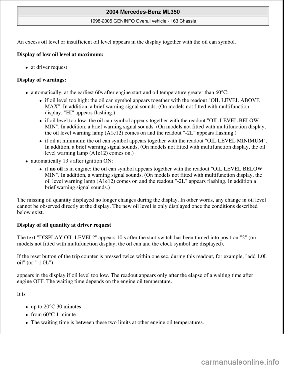
An excess oil level or insufficient oil level appears in the display together with the oil can symbol.
Display of low oil level at maximum:
at driver request
Display of warnings:
automatically, at the earliest 60s after engine start and oil temperature greater than 60°C:
if oil level too high: the oil can symbol appears together with the readout "OIL LEVEL ABOVE
MAX". In addition, a brief warning signal sounds. (On models not fitted with multifunction
display, "HI" appears flashing.)
if oil level too low: the oil can symbol appears together with the readout "OIL LEVEL BELOW
MIN". In addition, a brief warning signal sounds. (On models not fitted with multifunction display,
the oil level warning lamp (A1e12) comes on and the readout "-2L" appears flashing.)
if oil at minimum: the oil can symbol appears together with the readout "OIL LEVEL MINIMUM".
In addition, a brief warning signal sounds. (On models not fitted with multifunction display, the oil
level warning lamp (A1e12) comes on.)
automatically 13 s after ignition ON:
if no oil is in engine: the oil can symbol appears together with the readout "OIL LEVEL BELOW
MIN". In addition, a warning signal sounds. (On models not fitted with multifunction display, the
oil level warning lamp (A1e12) comes on and the readout "-2L" appears flashing. In addition a
brief warning signal sounds.)
The missing oil quantity displayed no longer changes during the display. In other words, any change in oil level
cannot be observed directly at the display. The new oil level is only displayed once the conditions described
below exist.
Display of oil quantity at driver request
The text "DISPLAY OIL LEVEL?" appears 10 s after the start switch has been turned into position "2" (on
models not fitted with multifunction display, the oil can and the clock symbol are displayed).
If the reset button of the trip counter is pressed twice within one sec. during this readout, for example, "add 1.0L
oil" (or "-1.0L")
appears in the display if oil level too low. The readout appears only after the elapse of a waiting time after
engine OFF. The waiting time depends on the engine oil temperature.
It is
up to 20°C 30 minutes
from 60°C 1 minute
The waiting time is between these two limits at other engine oil temperatures.
2004 Mercedes-Benz ML350
1998-2005 GENINFO Overall vehicle - 163 Chassis
me
Saturday, October 02, 2010 3:47:47 PMPage 210 © 2006 Mitchell Repair Information Company, LLC.