1997 MERCEDES-BENZ ML320 steering
[x] Cancel search: steeringPage 367 of 4133
Fig. 1: Locating Restraint System Components (2000 E Class Shown; Others Are Similar)
Courtesy of MERCEDES-BENZ OF NORTH AMERICA.
SERVICING
SRS AIR BAG label on driver-side door latch post indicates SRS replacement date for driver and passenger air
bag units. All SRS components must be thoroughly insp ected, including wiring harness. Before component
replacement, check for SRS fault codes by performing system operation check. See SYSTEM OPERATION
CHECK . SRS service life is 10 years from manufactured date, or 10 years from SRS replacement date after
accident related repairs are completed.
SYSTEM OPERATION CHECK
SRS warning light indicates air ba g and Emergency Tensioning Retracto r (ETR) system readiness. Turn
ignition on. SRS warning light will illuminate, then turn off after approximately 4-20 seconds indicating system
is functioning properly. If SRS warning light does not illuminate, illuminates while driving or is continuously
illuminated, there is a system faul t. Repair malfunctioning system. See DIAGNOSTICS
.
AIR BAG SAFETY PRECAUTIONS
Observe following precautions when working with air bag systems:
When working around steering column components and be fore any repairs are performed, disable air bag
system. See DISABLING & ACTIVATING AIR BAG SYSTEM
.
Before straightening any damage to body, or before performing electrical arc-welding, disable air bag
system. See DISABLING & ACTIVATING AIR BAG SYSTEM
.
Always wear safety glasses and gloves when ha ndling a deployed air bag module. Air bag module may
contain sodium hydroxide deposits wh ich are irritating to the skin.
DO NOT repair any portion of SRS wiring harness.
Always handle air bag module with trim cover away from your body. Always place air bag module on
workbench with trim cover up, away from loose objects.
DO NOT expose any SRS component to temp eratures in excess of 212 F (100 C).
DO NOT expose any SRS component to cleaning agen ts such as solvents, gasoline, lye, etc.
DO NOT connect Hand-Held Tester (6511 0001 99) to Data Link Connector (DLC) with ignition on.
Damage to HHT may result.
DO NOT connect HHT (6511 0001 99) to vehicle if a battery charger is connected to vehicle battery.
Damage to HHT may result.
ADJUSTMENTS
If fixing screws were not used durin g clockspring removal or clockspring was rotated during removal, turn
clockspring clockwise until resistance is detectable. Turn clockspring counterclockwise 2-2.5 turns until fixing
screws can be unscrewed holdi ng clockspring in this position.
DISABLING & ACTIVATI NG AIR BAG SYSTEM
2001 Mercedes-Benz ML320
2000-01 ACCESSORIES/SAFETY EQUIPMENT Merc edes-Benz - Air Bag Restraint Systems
me
Saturday, October 02, 2010 3:44:45 PMPage 3 © 2006 Mitchell Repair Information Company, LLC.
Page 368 of 4133
DISABLING SYSTEM
Before proceeding, see AIR BAG SAFETY PRECAUTIONS . Record radio presets and obtain anti-theft
code. Turn ignition switch to OFF position and remove ignition key. If welding on vehicle, disconnect negative
battery cable and disconnect air bag control module.
ACTIVATING SYSTEM
Ensure ignition is off. Reconnect air bag system co mponents (if disconnected). Reconnect negative battery
cable. Perform See SYSTEM OPERATION CHECK
.
DISPOSAL PROCEDURES
Several situations may arise requiring so me form of disposal action, including:
Scrapping a vehicle containing a deployed air bag module and-or ETR.
Scrapping a vehicle with a live air bag module and-or ETR.
Disposal of a live but electrically faulty air bag module and-or ETR.
Disposal of a deployed air bag module and-or ETR.
DEPLOYED AIR BAG OR ETR
Deployed air bag module and-or ETR unit can be thrown away. None of its components are reusable. Deployed
air bag module is NOT classified as hazardous material.
SCRAPPED VEHICLE
1. Before proceeding, follow service precautions. See AIR BAG SAFETY PRECAUTIONS . Move
vehicle outdoors to a remote area, away from work shop and other personnel. Disconnect and shield
negative battery cable. Open al l vehicle windows and doors.
2. Ensure air bag module is secured to steering wheel, and passenger air bag is secured to dash. Ensure ETR
seat belt assemblies are secured to "B" pillars and all seat belt buckles are latched. Remove loose ob
jects
CAUTION: On CL500, open doors before
disconnecting battery. Opening doors
allows windows to automa tically lower thus preventing roof seal damage.
WARNING: An undeployed air bag module or ET R should never be disposed of
without first being deplo yed. See SCRAPPED VEHICLE
. If deployment is
not possible, contact vehicle manuf acturer for further instructions.
WARNING: An undeployed air bag m odule and-or ETR seat belt CANNOT be disposed
of without first being de ployed. If this is not possible through procedures
outlined below, contact vehicle ma nufacturer for further instructions.
Perform remote deployment outdoors . Keep personnel at least 20 feet
away.
2001 Mercedes-Benz ML320
2000-01 ACCESSORIES/SAFETY EQUIPMENT Merc edes-Benz - Air Bag Restraint Systems
me
Saturday, October 02, 2010 3:44:45 PMPage 4 © 2006 Mitchell Repair Information Company, LLC.
Page 369 of 4133
from front seat. DO NOT allow anyone inside vehicle.
3. Disable air bag system. See DISABLING & ACTIVATING AIR BAG SYSTEM
. Connect Trigger
Device (126-589-00-90-00) and Adapter Cable (126 589 21 63 00) to SRS system connector (X29-9)
located at passenger footwell area. Move away from ve hicle as far as trigger device wiring will allow.
4. To deploy driver air bag and ETR, turn rotary knob on trigger device to position No. 1. Push battery
check push button and ignition push button simultane ously. Trigger light should illuminate indicating
driver air bag and ETR deployed. If trigger light is illuminated and driver air bag and-or ETR did not
deploy, driver air bag module and-or ETR is faulty. See UNDEPLOYED AIR BAG
-ETR .
5. To deploy passenger air bag detonator No. 1, turn ro tary knob on trigger device to position No. 2. Push
battery check push button and igni tion push button simultaneously. Tr igger light should illuminate
indicating passenger air bag detonator No. 1 deployed. If trigger light is illuminated and passenger air bag
detonator No. 1 did not deploy, passe nger air bag module is faulty. See UNDEPLOYED AIR BAG
-
ETR .
6. To deploy passenger air bag detonator No. 2, turn ro tary knob on trigger device to position No. 3. Push
battery check push button and igni tion push button simultaneously. Tr igger light should illuminate
indicating passenger air bag detonator No. 2 deployed. If trigger light is illuminated and passenger air bag
detonator No. 2 did not deploy, passe nger air bag module is faulty. See UNDEPLOYED AIR BAG
-
ETR .
UNDEPLOYED AIR BAG-ETR
After deploying procedures and-or diagnostic testing have confirmed air bag module and-or ETR is
undeployable, contact vehicle manufacture r for proper disposal instructions.
POST-COLLISION INSPECTION
When a vehicle has been involved in a collision, certain components of the passive restraint system must be
inspected or replaced. See AIR BAG/SRS COMPONENT INSPECTION & REPLACEMENT TABLES
article in the GENERAL INFORMATION section.
REMOVAL & INSTALLATION
CLOCKSPRING ASSEMBLY
Removal & Installation
1. Before proceeding, See AIR BAG SAFETY PRECAUTIONS . Disable air bag system. See
DISABLING & ACTIVATI NG AIR BAG SYSTEM
.
2. Remove driver air bag module. See DRIVER
-SIDE AIR BAG MODULE . Remove steering wheel bolt.
Using a puller, remove steering wheel. Disconnect lower clockspring connector. Turn 2 fixing screws
(locating on clockspring) countercl ockwise until clockspring cannot be rotated. Remove clockspring
mountin
g screws as necessary. Disconnect all necessary electrical connectors. Remove clockspring
WARNING:
Accidental air bag deployment is pos sible. Personal injury may result.
Read and follow all WARNINGS and AIR BAG SAFETY PRECAUTIONS
before working on ai r bag system or related components.
2001 Mercedes-Benz ML320
2000-01 ACCESSORIES/SAFETY EQUIPMENT Merc edes-Benz - Air Bag Restraint Systems
me
Saturday, October 02, 2010 3:44:45 PMPage 5 © 2006 Mitchell Repair Information Company, LLC.
Page 371 of 4133
1. Before proceeding, See AIR BAG SAFETY PRECAUTIONS . Disable air bag system. See
DISABLING & ACTIVATI NG AIR BAG SYSTEM
. Remove ignition key. Remove radio. Push up
and pull out heater control panel. Unplug 2 connectors. Remove scre w in middle of storage tray.
2. Bend up at top corners and lift out storage tray. Rem ove screws below storage tray. Lift wood trim panel
at rear, pull down and out of catches. Unplug swit ch connectors and remove wood trim panel. Unplug
connectors at control module and remove Torx mounting screws. Remove control module.
3. To install, reverse removal proce dure. Ensure SRS control module arro w points to front of vehicle. Set
parameters and program new SRS control module wi th Hand-Held Tester (965 589 00 01 00). Activate
air bag system. Perform system operation check to ensure system is functioning properly. See SYSTEM
OPERATION CHECK .
Removal & Installation (CLK & SLK)
1. Before proceeding, See AIR BAG SAFETY PRECAUTIONS . Disable air bag system. See
DISABLING & ACTIVATI NG AIR BAG SYSTEM
. Remove ignition key. Remove cover on center
console. Remove cover on shift lever. Remove ash tray housing with storage compartment at front of
center console. Unplug connectors at control module and remove Torx mounting screws. Remove control
module.
2. To install, reverse removal proce dure. Ensure SRS control module arro w points to front of vehicle. Set
parameters and program new SRS control module wi th Hand-Held Tester (965 589 00 01 00). Activate
air bag system. Perform system operation check to ensure system is functioning properly. See SYSTEM
OPERATION CHECK .
DRIVER-SIDE AIR BAG MODULE
Removal & Installation
1. Before proceeding, See AIR BAG SAFETY PRECAUTIONS . Disable air bag system. See
DISABLING & ACTIVATI NG AIR BAG SYSTEM
. Remove ignition key. Remove 2 Torx screws
from rear of steering wheel. Lift off air bag m odule enough to unplug connector from rear of module.
Place module away from work area, with pad facing upward.
2. To install, reverse removal procedure. Tighten Torx screws to specification. See TORQUE
SPECIFICATIONS . Activate air bag system. Perform system operation ch eck to ensure system is
functioning properly. See SYSTEM OPERATION CHECK
.
SIDE AIR BAG UNIT (DRIVER-SIDE & PASSENGER-SIDE)
Removal & Installation
1. Before proceeding, See AIR BAG SAFETY PRECAUTIONS . Disable air bag system. See
DISABLING & ACTIVATI NG AIR BAG SYSTEM
. Remove ignition key. Drill out rivets at
retaining plate of side air bag unit. Pull air bag unit out of door. Disconnect connector at driver-side air
bag squib. Remove unit from vehicle. See Fig. 2.
NOTE: Air bag module and steer
ing wheel must be replaced following a collision in
which air bag was deployed.
2001 Mercedes-Benz ML320
2000-01 ACCESSORIES/SAFETY EQUIPMENT Merc edes-Benz - Air Bag Restraint Systems
me
Saturday, October 02, 2010 3:44:45 PMPage 7 © 2006 Mitchell Repair Information Company, LLC.
Page 432 of 4133
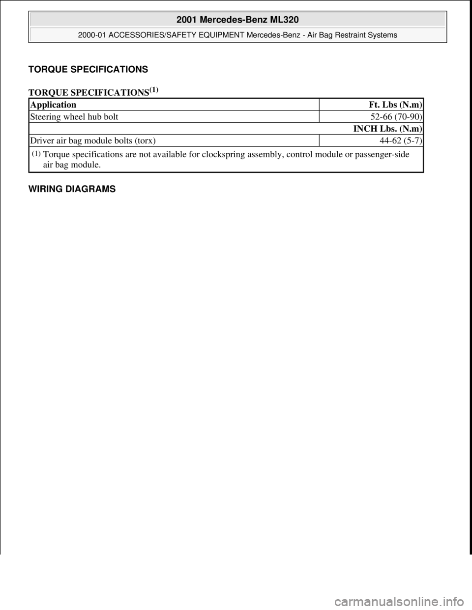
TORQUE SPECIFICATIONS
TORQUE SPECIFICATIONS
(1)
WIRING DIAGRAMS
ApplicationFt. Lbs (N.m)
Steering wheel hub bolt52-66 (70-90)
INCH Lbs. (N.m)
Driver air bag module bolts (torx)44-62 (5-7)
(1)Torque specifications are not av ailable for clockspring assembly, control module or passenger-side
air bag module.
2001 Mercedes-Benz ML320
2000-01 ACCESSORIES/SAFETY EQUIPMENT Merc edes-Benz - Air Bag Restraint Systems
me
Saturday, October 02, 2010 3:44:46 PMPage 68 © 2006 Mitchell Repair Information Company, LLC.
Page 468 of 4133

1
Contents
IntroductionProduct information .......................... 7
Roadside assistance ......................... 10
Where to find it ................................ 14
Reporting Safety Defects ................ 16Instruments and controlsInstruments and controls ............... 18 Center console .............................. 20
Overhead control panel ............... 21OperationVehicle keys ...................................... 24
Start lock-out .................................... 25
General notes on the central locking system ............... 26
Central locking system ................... 26 Radio frequency
remote control .............................. 26
Unlocking the liftgate .................. 28
Panic button .................................. 28
Mechanical keys ........................... 29 Doors ................................................. 30
Central locking switch .................... 32 Automatic central locking .......... 32
Emergency unlocking in case of accident ................................... 33
Liftgate .............................................. 34
Antitheft alarm system ................... 35
Tow-away alarm and glass breakage sensor ............... 36
Seats, front ....................................... 37
Manual seats ................................ 39
Power seats ................................... 40
Head restraint ...............................41
Heated seats ..................................... 44
Seat belts and integrated restraint system .......................... 46
Seat belts .......................................... 46 Seat belt nonusage
warning system ............................ 47
BabySmart
TM airbag
deactivation system ................... 53
Self-test BabySmart
TM
without special child
seat installed ................................ 53 Supplemental restraint
system (SRS) ................................ 54
Emergency tensioning retractor (ETR) ............................. 55
Airbags .............................................. 56 Safety guidelines for the
seat belt, emergency
tensioning retractor
and airbag ..................................... 63
Infant and child
restraint systems .......................... 65
Adjustable steering wheel .............. 70
Inside rear view mirror .................. 71 Antiglare night position .............. 71
Exterior rear view mirrors ............. 73 Exterior rear view mirror,
electrically folding ....................... 75
Instrument cluster ........................... 76
Indicator lamps in the instrument cluster ...................... 78
Trip computer ................................... 83
Flexible service system (FSS) ........ 87
Engine oil level indicator ................ 89
Exterior lamp switch ....................... 90
Page 469 of 4133

2
Contents
Fog lamp switch (except Canada) ........................... 92
Fog lamp switch (Canada only) .............................. 93
Hazard warning flasher switch ............................................ 94
Headlamp cleaning system ............ 94
Windshield wiper/washer switch ............................................ 95
Rear window wiper/washer ........... 96
Climate control ................................. 98 Basic setting – Heater ............... 100
Basic setting –
Air conditioner ........................... 100
Special setting ............................ 101
Dust filter .................................... 102
Air recirculation ......................... 102
Rear window defroster .............. 103
Power windows ............................... 104
Rear quarter windows ................... 106
Sliding/pop-up roof ....................... 107
Skyview Top .................................... 109
Interior lighting ..............................110
Sun visors ........................................113 Illuminated vanity mirrors ........... 113
Interior ............................................. 114
Storage compartments, armrest and cup holder ............ 114
Glove box ...................................... 115
Armrest in rear bench seat ........... 117
Ashtrays ........................................... 118
Lighter .............................................. 119
Split rear seat bench ..................... 120 Easy entry/exit feature ............. 123
Rear seat head restraints ......... 124
Third row seats .............................. 126
Removable cargo floor plates ...... 129
Enlarged cargo area .......................131
Cargo tie-down rings .....................132
Hooks ...............................................133
Partition net ....................................133
Loading instructions ......................136
Cargo area cover blind ..................137
Telephone, general .........................139
Cellular telephone ..........................139
Garage door opener ....................... 140
DrivingControl and operation of radio transmitters ..................... 146
The first 1 000 miles (1 500 km) ................................. 147
Maintenance ................................... 147
Tele Aid ........................................... 148
Catalytic converter ........................ 160
Emission control ............................ 161
Steering lock ................................... 162
Starting and turning off the engine .................................. 164
Automatic transmission ............... 165
Parking brake ................................. 173
Driving instructions ...................... 174 Drive sensibly – save fuel ......... 174
Drinking and driving ................. 174
Pedals ........................................... 174
Power assistance ........................ 175
Brakes .......................................... 175
Driving off ................................... 176
Parking ........................................ 176
Tires ............................................. 177
Page 470 of 4133

3
Contents Snow chains ................................ 179
Winter driving instructions ...... 180
Deep water .................................. 181
Passenger compartment ........... 182
Traveling abroad ........................ 182
Off-Road driving ............................. 183
Trailer towing ................................. 190
Cruise control ................................. 196
Brake assist system (BAS) ............ 199
Antilock brake system (ABS) ....... 201
Four-wheel electronic traction system (4-ETS+) ..........203
Electronic brake proportioning (EBP) ..................204
Electronic stability program (ESP) ...........................................205
Transmission control – LOW RANGE mode ...................209
What you should know at the gas station ....................... 212
Check regularly and before a long trip ....................... 215
Instrument cluster displayMalfunction and indicator lamps in the
instrument cluster .....................218
On-board diagnostic system –
Check engine malfunction
indicator lamp .............................218
Brake warning lamp ...................219
Supplemental restraint system
(SRS) indicator lamp .................. 219
Fuel reserve warning ................ 220
Electronic stability
program (ESP) / Electronic
traction system (ETS) –
warning lamp ............................. 221
BAS/ESP malfunction
indicator lamp ............................ 221
4-ETS malfunction
indicator lamp ............................ 221
LOW RANGE
indicator lamp ............................ 221
ABS malfunction
indicator lamp ............................ 222 Adjustable steering wheel –
indicator lamp .............................222
AIRBAG OFF
indicator lamp .............................222
Seat belt warning lamp .............223
Charge indicator lamp ...............223
Low engine oil level
warning lamp ..............................224
Low engine coolant
level warning ..............................224
Brake pad wear
indicator lamp .............................225
FSS indicator ...............................225