1997 MAZDA MIATA belt
[x] Cancel search: beltPage 1 of 514

AIR BAG RESTRAINT SYSTEM
1997 ACCESSORIES/SAFETY EQUIPMENT Mazda - Air Bag Restraint System
DESCRIPTION & OPERATION
The Supplemental Restraint System (SRS), when used in conjunction with seat belt, provides increased
protection for driver and front passenger in a frontal collision. The air bag restraint system consists of AIR BAG
warning light, driver-side air bag module, passenger-side air bag module, clockspring, SAS unit, and wiring
harness. See Fig. 1
. WARNING:To avoid injury from accidental air bag deployment, read and carefully
follow all WARNINGS and SERVICE PRECAUTIONS
.
1997 Mazda MX-5 Miata
AIR BAG RESTRAINT SYSTEM 1997 ACCESSORIES/SAFETY EQUIPMENT Mazda - Air Bag Restraint System
1997 Mazda MX-5 Miata
AIR BAG RESTRAINT SYSTEM 1997 ACCESSORIES/SAFETY EQUIPMENT Mazda - Air Bag Restraint System
Microsoft
Sunday, July 05, 2009 1:40:47 PMPage 1 © 2005 Mitchell Repair Information Company, LLC.
Microsoft
Sunday, July 05, 2009 1:40:53 PMPage 1 © 2005 Mitchell Repair Information Company, LLC.
Page 137 of 514

GENERATOR & REGULATOR
1997 STARTING & CHARGING SYSTEMS Mazda - Generators & Regulators
DESCRIPTION & OPERATION
Generator is a conventional 3-phase, self-rectifying type with 6 diodes (3 positive and 3 negative) that rectify
current. Internal regulator is solid-state type.
ADJUSTMENTS
BELT DEFLECTION
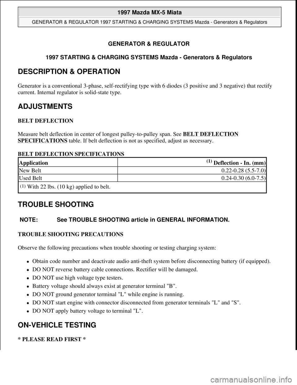
Measure belt deflection in center of longest pulley-to-pulley span. See BELT DEFLECTION
SPECIFICATIONS table. If belt deflection is not as specified, adjust as necessary.
BELT DEFLECTION SPECIFICATIONS
TROUBLE SHOOTING
TROUBLE SHOOTING PRECAUTIONS
Observe the following precautions when trouble shooting or testing charging system:
Obtain code number and deactivate audio anti-theft system before disconnecting battery (if equipped).
DO NOT reverse battery cable connections. Rectifier will be damaged.
DO NOT use high voltage type testers.
Battery voltage should always exist at generator terminal "B".
DO NOT ground generator terminal "L" while engine is running.
DO NOT start engine with connector disconnected from generator terminals "L" and "S".
DO NOT apply battery voltage to terminal "L".
ON-VEHICLE TESTING
* PLEASE READ FIRST *
Application(1) Deflection - In. (mm)
New Belt0.22-0.28 (5.5-7.0)
Used Belt0.24-0.30 (6.0-7.5)
(1)With 22 lbs. (10 kg) applied to belt.
NOTE: See TROUBLE SHOOTING article in GENERAL INFORMATION.
1997 Mazda MX-5 Miata
GENERATOR & REGULATOR 1997 STARTING & CHARGING SYSTEMS Mazda - Generators & Regulators
1997 Mazda MX-5 Miata
GENERATOR & REGULATOR 1997 STARTING & CHARGING SYSTEMS Mazda - Generators & Regulators
Microsoft
Sunday, July 05, 2009 1:53:15 PMPage 1 © 2005 Mitchell Repair Information Company, LLC.
Microsoft
Sunday, July 05, 2009 1:53:20 PMPage 1 © 2005 Mitchell Repair Information Company, LLC.
Page 138 of 514

GENERATOR OUTPUT
1. Connect an ammeter (100-amp minimum) in-line between generator terminal "B" connector and terminal
"B" of wiring harness connector. See Fig. 1
. Turn headlights and all accessories on. Depress brake pedal.
Operate engine at 2500-3000 RPM.
2. Measure and record generator output. See GENERATOR MAXIMUM RATED OUTPUT
table. If
amperage is as specified, go to next step. If amperage is not as specified, repair or replace generator.
3. Turn off headlights and all accessories. Release brake pedal. Operate engine at 2500-3000 RPM and
measure amperage under no-load condition. No-load amperage should be 5 amps or greater. If amperage
is as specified, go to next step. If amperage is not as specified, repair or replace generator.
4. Operate engine at 2500-3000 RPM. Measure voltage between ground and terminals "S" and "L". If 14.1-
14.7 volts does not exist, repair or replace generator. If 14.1-14.7 volts exists, generator output is okay.
GENERATOR MAXIMUM RATED OUTPUT NOTE: Check generator wiring harness connections and drive belt tension. Battery
must be fully charged before testing. Wait at least 30 seconds after starting
engine before measuring system voltage.
CAUTION: Ensure generator terminal "B" does not contact ground.
ApplicationAmps
A/T70
M/T65
1997 Mazda MX-5 Miata
GENERATOR & REGULATOR 1997 STARTING & CHARGING SYSTEMS Mazda - Generators & Regulators
Microsoft
Sunday, July 05, 2009 1:53:16 PMPage 2 © 2005 Mitchell Repair Information Company, LLC.
Page 200 of 514

SOLENOIDS & SOLENOID VALVES
SOLENOIDS & SOLENOID VALVES
SWITCHES
SWITCHES
MISCELLANEOUS
MISCELLANEOUS
Vehicle Speed Sensor (VSS)On speedometer assembly.
Water Temperature Sender UnitOn center of engine. See Fig. 1 .
Washer Fluid Level SensorOn washer fluid reservoir. See Fig. 1 .
ComponentComponent Location
AT Interlock SolenoidIn steering column, near ignition switch. See Fig. 2 .
EC-AT Solenoid ValveOn left side of transmission.
EGR Solenoid Valve (Vacuum)On right side of engine compartment. See Fig. 1 .
EGR Solenoid Valve (Vent)On right side of engine compartment. See Fig. 1 .
Fourth Gear Solenoid ValveOn left side of transmission.
Idle Air Control ValveOn right side, front of engine compartment. See Fig. 1 .
PRC Solenoid ValveOn right side, front of engine. See Fig. 1 .
Purge Solenoid ValveOn right strut tower. See Fig. 1 .
ComponentComponent Location
Back-Up Lamp Switch (M/T)On right side of transmission. See Fig. 1 .
Brake SwitchOn bracket, above brake pedal. See Fig. 2 .
Buckle SwitchOn driver side seat belt buckle. See Fig. 3 .
Clutch Switch (M/T)On bracket, above clutch pedal. See Fig. 2 .
Hold SwitchUnder right side of center console.
Key Reminder SwitchIn steering column, near ignition switch.
Neutral Switch (M/T)On right side of transmission. See Fig. 1 .
Oil Pressure SwitchOn right side of engine. See Fig. 1 .
"P" Range SwitchUnder center console, on base of gear selector.
Parking Brake SwitchOn base of parking brake lever. See Fig. 4 .
Power Steering Pressure SwitchOn power steering pump assembly.
Refrigerant Pressure SwitchIn front of engine compartment, near radiator support. See Fig. 1 .
Starter Interlock Switch (M/T)On bracket, above clutch pedal. See Fig. 2 .
ThermoswitchUnder right side of dash.
Transmission Range SwitchOn left side of transmission.
ComponentComponent Location
1997 Mazda MX-5 Miata
1997 MAZDA MX-5 Miata
Microsoft
Sunday, July 05, 2009 1:54:00 PMPage 3 © 2005 Mitchell Repair Information Company, LLC.
Page 210 of 514

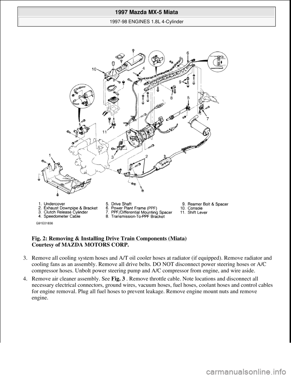
Fig. 2: Removing & Installing Drive Train Components (Miata)
Courtesy of MAZDA MOTORS CORP.
3. Remove all cooling system hoses and A/T oil cooler hoses at radiator (if equipped). Remove radiator and
cooling fans as an assembly. Remove all drive belts. DO NOT disconnect power steering hoses or A/C
compressor hoses. Unbolt power steering pump and A/C compressor from engine, and wire aside.
4. Remove air cleaner assembly. See Fig. 3
. Remove throttle cable. Note locations and disconnect all
necessary electrical connectors, ground wires, vacuum hoses, fuel hoses, coolant hoses and control cables
for engine removal. Plug all fuel hoses to prevent leakage. Remove engine mount nuts and remove
en
gine.
1997 Mazda MX-5 Miata
1997-98 ENGINES 1.8L 4-Cylinder
Microsoft
Sunday, July 05, 2009 1:55:15 PMPage 4 © 2005 Mitchell Repair Information Company, LLC.
Page 214 of 514

Fig. 5: Removing Engine Components (Protege)
Courtesy of MAZDA MOTORS CORP.
2. Lower vehicle. Remove air cleaner assembly. Remove battery/carrier assembly. Remove throttle cable
and air intake duct across radiator (if equipped).
3. Remove all drive belts. DO NOT disconnect power steering hoses or A/C compressor hoses. Unbolt
power steering pump and A/C compressor from engine, and wire aside.
4. Note locations and disconnect all necessary electrical connectors, ground wires, vacuum hoses, fuel
hoses, coolant hoses and control cables for engine removal.
5. Plug all fuel hoses to avoid leakage. Attach engine support bar or engine hoist to secure engine. Raise
vehicle. Disconnect exhaust manifold down pipe and exhaust brackets from engine. On A/T models,
remove shift control cable.
6. On M/T models, remove shift control linkage and extension bar. Remove clutch release cylinder and fluid
line bracket from transaxle housing, leaving fluid line connected to cylinder. Secure cylinder away from
transaxle.
7. On all models, remove transmission wiring harness connectors and speedometer cable. Remove axle shaft
nuts from hubs. Disconnect stabilizer bar from lower control arms. Separate lower ball joints and steering
tie-rod ends from steering knuckles.
8. Pry axle shafts out of transaxle. Remove and discard circlip from axle shafts. For further information on
axle shafts, see appropriate article in DRIVE AXLES.
9. Remove transaxle mount nuts from crossmember and loosen crossmember bolts. See Fig. 6
. Lower
vehicle and attach engine hoist for engine removal. Remove engine front mount and transaxle top mount
from inner fender panels. Remove transaxle crossmember. Remove engine and transaxle assembly from
top of vehicle.
10. To install, reverse removal procedure. Tighten bolts and nuts to specifications. See TORQUE
SPECIFICATIONS . Fill all fluids to correct level. Prime fuel system before attempting to start engine.
See FUEL PRESSURE RELEASE & PRIMING
. Bleed cooling system. See COOLING SYSTEM
BLEEDING.
1997 Mazda MX-5 Miata
1997-98 ENGINES 1.8L 4-Cylinder
Microsoft
Sunday, July 05, 2009 1:55:15 PMPage 8 © 2005 Mitchell Repair Information Company, LLC.
Page 216 of 514

2. Disconnect throttle cable. Remove fuel lines from fuel rail and pressure regulator. Remove throttle body
intake duct housing and throttle body. Remove by-pass air control valve and solenoid valves. Remove
upper intake manifold (if equipped).
3. Remove intake manifold support bracket from underneath manifold. Disconnect injector harness
connectors, and remove injectors/fuel rail assembly. Remove intake manifold and gasket.
Installation
1. Ensure all gasket surfaces are clean and flat. Using NEW gasket, install intake manifold to cylinder head.
Tighten manifold bolts/nuts evenly to specification, starting from center bolt and alternating outward. See
TORQUE SPECIFICATIONS
. Install support bracket underneath intake manifold.
2. Install gasket and upper intake manifold (if equipped). Tighten bolts/nuts evenly to specification,
alternating from top to bottom. See TORQUE SPECIFICATIONS
.
3. To complete installation, reverse removal procedure. Ensure throttle cable has .04-.12" (1-3 mm) free
play. Ensure injectors twist freely and are not cocked in insulator "O" rings. Refill engine with coolant.
EXHAUST MANIFOLD
Removal & Installation
1. Remove air cleaner intake duct from top of radiator/fan assembly (if equipped). Disconnect oxygen
sensor. Remove heat shields. Disconnect down pipe from exhaust manifold. Remove exhaust manifold.
2. To install, reverse removal procedure. Ensure all mating surfaces are clean and flat. Install NEW exhaust
manifold gasket to cylinder head. Tighten manifold bolts evenly to specification, starting from center bolt
and alternating outward. See TORQUE SPECIFICATIONS
.
CYLINDER HEAD
Removal
1. Release residual pressure from fuel system. See FUEL PRESSURE RELEASE & PRIMING . Drain
engine coolant. Note locations and disconnect all necessary electrical connectors, ground wires, vacuum
hoses, fuel hoses, coolant hoses and control cables for cylinder head removal. Plug all fuel hoses to avoid
leakage.
2. Remove spark plug wires from spark plugs. Remove all drive belts. Remove water pump pulley. Remove
timing belt. See TIMING BELT
. Remove camshaft/rocker cover.
3. Remove front exhaust pipe. Remove intake manifold support bracket. Loosen all cylinder head bolts
evenly, in 3 steps, in reverse of tightening sequence. See Fig. 7
. Remove bolts and cylinder head
assembly.
Inspection
Carefully clean carbon and gasket material from all mating surfaces. Clean threads of cylinder head bolts. Use a
tap to clean threads in engine block. Check cylinder head for warpage. Resurface or replace head if it is not
within specification. Check valve train components. Replace or resurface components if they are not within
1997 Mazda MX-5 Miata
1997-98 ENGINES 1.8L 4-Cylinder
Microsoft
Sunday, July 05, 2009 1:55:15 PMPage 10 © 2005 Mitchell Repair Information Company, LLC.
Page 217 of 514

specification. See CYLINDER HEAD and VALVES & VALVE SPRINGS tables under ENGINE
SPECIFICATIONS .
Installation
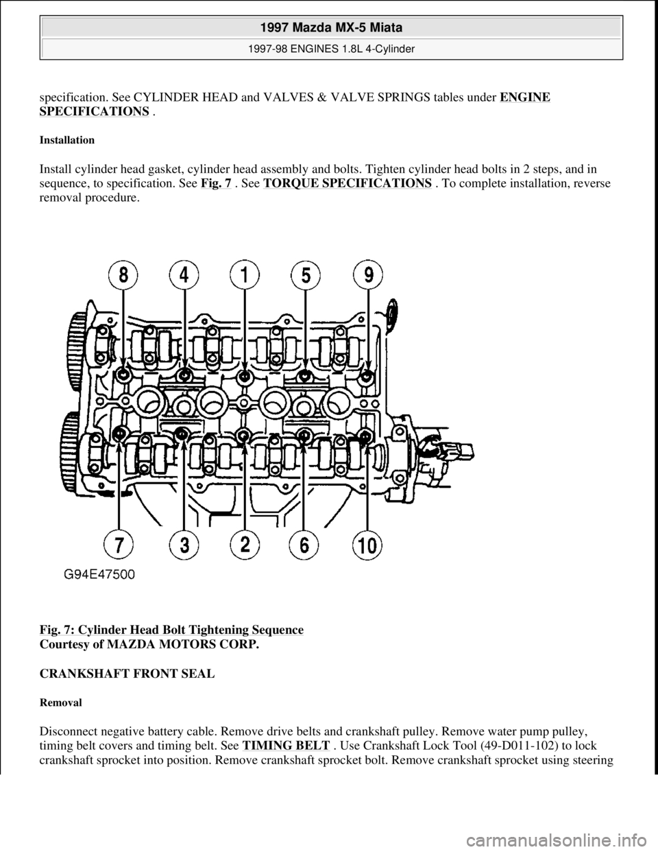
Install cylinder head gasket, cylinder head assembly and bolts. Tighten cylinder head bolts in 2 steps, and in
sequence, to specification. See Fig. 7
. See TORQUE SPECIFICATIONS . To complete installation, reverse
removal procedure.
Fig. 7: Cylinder Head Bolt Tightening Sequence
Courtesy of MAZDA MOTORS CORP.
CRANKSHAFT FRONT SEAL
Removal
Disconnect negative battery cable. Remove drive belts and crankshaft pulley. Remove water pump pulley,
timing belt covers and timing belt. See TIMING BELT
. Use Crankshaft Lock Tool (49-D011-102) to lock
crankshaft sprocket into position. Remove crankshaft sprocket bolt. Remove crankshaft sprocket usin
g steering
1997 Mazda MX-5 Miata
1997-98 ENGINES 1.8L 4-Cylinder
Microsoft
Sunday, July 05, 2009 1:55:15 PMPage 11 © 2005 Mitchell Repair Information Company, LLC.