1997 MAZDA MIATA belt
[x] Cancel search: beltPage 316 of 514
COMPRESSOR
Removal & Installation
1. Before disconnecting negative battery cable, obtain radio anti-theft code from vehicle owner. Disconnect
negative battery cable.
2. Raise and support front of vehicle with safety stands. Discharge A/C system using approved refrigerant
recovery/recycling equipment. Remove splash shield and air guide.
3. Disconnect compressor clutch connector. Disconnect refrigerant lines from compressor, and plug open
fittings. Remove compressor drive belt. Remove compressor bolts and compressor. To install, reverse
removal procedure. Adjust drive belt deflection. Apply clean compressor oil to "O" ring before
connecting fittings. DO NOT apply compressor oil to fitting nuts. Evacuate and charge A/C system.
Check for leaks.
CONDENSER & RECEIVER-DRIER
Removal
Raise and support front of vehicle with safety stands. Discharge A/C system using approved refrigerant
recovery/recycling equipment. Remove splash shield and air guide. Remove condenser. Remove receiver-drier.
Plug open fittings.
Installation
To install, reverse removal procedure. Apply clean compressor oil to "O" rings before connecting fittings. DO
NOT apply compressor oil to fitting nuts. If installing new condenser, add 1.0 ounce of compressor oil to A/C
compressor. If installing new receiver-drier, add .3 ounce of compressor oil to A/C compressor. Evacuate and
charge A/C system. Check for leaks.
EVAPORATOR UNIT
Removal
1. Discharge A/C system using approved refrigerant recovery/recycling equipment. Disconnect refrigerant
pipes from evaporator tubes at engine compartment firewall and plug open fittings. Remove passenger-
side instrument panel undercover. Remove glove box.
2. Disconnect electrical connectors. Loosen seal plates between evaporator unit, heater unit and blower unit.
Remove evaporator unit. Disassemble evaporator unit to remove evaporator core and thermo-switch. See WARNING:To avoid injury from accidental air bag deployment, read and follow all
SERVICE PRECAUTIONS and DISABLING & ACTIVATING AIR BAG
SYSTEM procedures in AIR BAG RESTRAINT SYSTEM article in the
ACCESSORIES/SAFETY EQUIPMENT section.
NOTE: For removal and installation procedures not covered in this article, see HEATER
SYSTEM article.
1997 Mazda MX-5 Miata
A/C-HEATER SYSTEM - MANUAL 1997 Manual A/C-Heater System
Microsoft
Sunday, July 05, 2009 1:41:48 PMPage 7 © 2005 Mitchell Repair Information Company, LLC.
Page 322 of 514
MAINTENANCE SERVICE INFORMATION
SEVERE & NORMAL SERVICE DEFINITIONS
Service is recommended at mileage intervals based on vehicle operation. Service schedules are based on
following primary operating conditions:
Normal Service
Driven More Than 10 Miles Daily
No Operating Conditions From Severe Service Schedule
Severe Service (Unique Driving Conditions)
Repeated Short Distance Driving
Dusty Conditions
Extended Use Of Brakes
Salt Or Other Corrosive Materials On The Roads
Rough Or Muddy Roads
Extended Idling Or Low Speed Operation
Extended Operation In Extreme Temperatures
CAMSHAFT TIMING BELT
Replace camshaft timing belt at 60,000 mile intervals.
The condition of camshaft drive belts should always be checked on vehicles which have more than 50,000
miles. Although some manufacturers do not recommend belt replacement at a specified mileage, others require
it at 60,000-100,000 miles. A camshaft drive belt failure may cause extensive damage to internal engine
components on most engines, although some designs do not allow piston-to-valve contact. These designs are
often called "Free Wheeling".
Many manufacturers changed their maintenance and warranty schedules in the mid-1980's to reflect timing belt
inspection and/or replacement at 50,000-60,000 miles. Most service interval schedules in this manual reflect
these changes.
Belts or components should be inspected and replaced if any of the following conditions exist: NOTE: Use the Severe Service schedule if the vehicle to be serviced is operated under
ANY (one or more) of these conditions:
CAUTION: Failure to replace a faulty camshaft timing belt may result in serious
engine damage.
1997 Mazda MX-5 Miata
MAINTENANCE INFORMATION 1997 MAINTENANCE Mazda Maintenance Information
Microsoft
Sunday, July 05, 2009 1:41:19 PMPage 2 © 2005 Mitchell Repair Information Company, LLC.
Page 323 of 514
Cracks Or Tears In Belt Surface
Missing, Damaged, Cracked Or Rounded Teeth
Oil Contamination
Damaged Or Faulty Tensioners
Incorrect Tension Adjustment
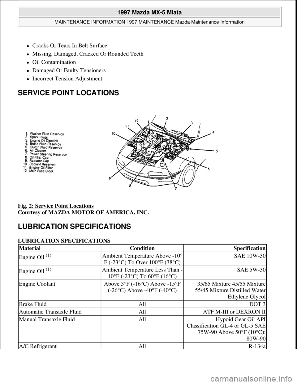
SERVICE POINT LOCATIONS
Fig. 2: Service Point Locations
Courtesy of MAZDA MOTOR OF AMERICA, INC.
LUBRICATION SPECIFICATIONS
LUBRICATION SPECIFICATIONS
MaterialConditionSpecification
Engine Oil (1) Ambient Temperature Above -10°
F (-23°C) To Over 100°F (38°C)SAE 10W-30
Engine Oil (1) Ambient Temperature Less Than -
10°F (-23°C) To 60°F (16°C)SAE 5W-30
Engine CoolantAbove 3°F (-16°C) Above -15°F
(-26°C) Above -40°F (-40°C)35/65 Mixture 45/55 Mixture
55/45 Mixture Distilled Water
Ethylene Glycol
Brake FluidAllDOT 3
Automatic Transaxle FluidAllATF M-III or DEXRON II
Manual Transaxle FluidAllHypoid Gear Oil API
Classification GL-4 or GL-5 SAE
75W-90 Above 50°F (10°C):
80W-90
A/C RefrigerantAllR-134a
1997 Mazda MX-5 Miata
MAINTENANCE INFORMATION 1997 MAINTENANCE Mazda Maintenance Information
Microsoft
Sunday, July 05, 2009 1:41:19 PMPage 3 © 2005 Mitchell Repair Information Company, LLC.
Page 328 of 514

Supplemental air bag system, seat belts and related components are warranted for 5 years or 60,000 miles,
whichever comes first, against defects in materials and workmanship.
REPLACEMENT PARTS & ACCESSORIES
Manufacturer-supplied parts and accessories are warranted against defects in material or workmanship for 12
months without regard to mileage. If installed by a Mazda dealer, part or accessory will be repaired or replaced
without charge during warranty period. If not installed by a dealer, part or accessory will be repaired or replaced
without charge for parts, but labor cost will be responsibility of owner.
EMISSION DEFECT WARRANTY (EXCEPT CALIFORNIA)
Warrants that vehicle was designed, built and equipped to conform with applicable Federal emission regulations
at time of sale and that vehicle is free of defects in materials and workmanship which may cause vehicle to fail
to conform with applicable regulations for 5 years or 50,000 miles, whichever occurs first.
EMISSION PERFORMANCE WARRANTY (EXCEPT CALIFORNIA)
Covers all repairs, adjustments and replacements if vehicle fails to conform to applicable emission standards
and such failure results in vehicle owner bearing a penalty or other sanction under local, state or Federal law.
Warranty period is 5 years or 50,000 miles, whichever comes first. After 2 years or 24,000 miles, manufacturer
will make necessary adjustments, repairs and replacements at no cost to owner only when noncompliance is
caused by failure of components which have been installed in vehicle for sole or primary purpose of reducing
vehicle emissions. See copy of warranty for specific components covered.
EMISSION DEFECT WARRANTY (CALIFORNIA)
For 3 years or 50,000 miles, whichever occurs first, any defective emission-related part on vehicle will be
repaired or replaced by manufacturer at no cost to owner. Certain emission-related parts are covered for repair
or replacement for 7 years or 70,000 miles, whichever occurs first. See copy of warranty for specific
components covered.
EMISSION PERFORMANCE WARRANTY (CALIFORNIA)
For 3 years or 50,000 miles, manufacturer will make all necessary repairs and adjustments to ensure vehicle
passes a required Smog Check inspection.
FUSES & CIRCUIT BREAKERS
FUSE PANEL LOCATION
Fuse box is located above driver's left knee, accessible through a removable cover. The main fuse block is
located at the right rear of the engine compartment.
The Trunk Mounted Fuse Panel is located on the ri
ght side of the trunk, near the trunk hinge.
1997 Mazda MX-5 Miata
MAINTENANCE INFORMATION 1997 MAINTENANCE Mazda Maintenance Information
Microsoft
Sunday, July 05, 2009 1:41:19 PMPage 8 © 2005 Mitchell Repair Information Company, LLC.
Page 343 of 514
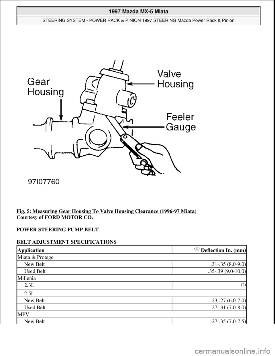
Fig. 5: Measuring Gear Housing To Valve Housing Clearance (1996-97 Miata)
Courtesy of FORD MOTOR CO.
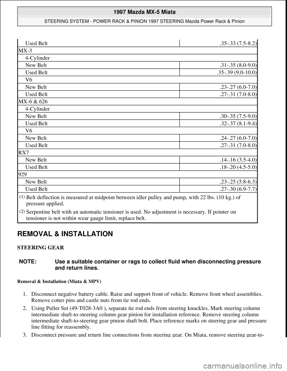
POWER STEERING PUMP BELT
BELT ADJUSTMENT SPECIFICATIONS
Application(1) Deflection In. (mm)
Miata & Protege
New Belt.31-.35 (8.0-9.0)
Used Belt.35-.39 (9.0-10.0)
Millenia
2.3L(2)
2.5L
New Belt.23-.27 (6.0-7.0)
Used Belt.27-.31 (7.0-8.0)
MPV
New Belt.27-.35 (7.0-7.5)
1997 Mazda MX-5 Miata
STEERING SYSTEM - POWER RACK & PINION 1997 STEERING Mazda Power Rack & Pinion
Microsoft
Sunday, July 05, 2009 1:39:26 PMPage 8 © 2005 Mitchell Repair Information Company, LLC.
Page 344 of 514
REMOVAL & INSTALLATION
STEERING GEAR
Removal & Installation (Miata & MPV)
1. Disconnect negative battery cable. Raise and support front of vehicle. Remove front wheel assemblies.
Remove cotter pins and castle nuts from tie rod ends.
2. Using Puller Set (49-T028-3A0 ), separate tie rod ends from steering knuckles. Mark steering column
intermediate shaft-to-steering column gear pinion for installation reference. Remove steering column
intermediate shaft-to-steering gear pinion shaft bolt. Place reference marks on steering gear and pressure
line fitting for reassembly.
3. Disconnect pressure and return line connections from steering gear. On Miata, remove steering gea
r-to-
Used Belt.35-.33 (7.5-8.2)
MX-3
4-Cylinder
New Belt.31-.35 (8.0-9.0)
Used Belt.35-.39 (9.0-10.0)
V6
New Belt.23-.27 (6.0-7.0)
Used Belt.27-.31 (7.0-8.0)
MX-6 & 626
4-Cylinder
New Belt.30-.35 (7.5-9.0)
Used Belt.32-.37 (8.1-9.4)
V6
New Belt.24-.27 (6.0-7.0)
Used Belt.27-.31 (7.0-8.0)
RX7
New Belt.14-.16 (3.5-4.0)
Used Belt.18-.20 (4.5-5.0)
929
New Belt.23-.25 (5.8-6.3)
Used Belt.27-.30 (6.9-7.7)
(1)Belt deflection is measured at midpoint between idler pulley and pump, with 22 lbs. (10 kg.) of
pressure applied.
(2)Serpentine belt with an automatic tensioner is used. No adjustment is necessary. If pointer on
tensioner is not within wear gauge limit, replace belt.
NOTE: Use a suitable container or rags to collect fluid when disconnecting pressure
and return lines.
1997 Mazda MX-5 Miata
STEERING SYSTEM - POWER RACK & PINION 1997 STEERING Mazda Power Rack & Pinion
Microsoft
Sunday, July 05, 2009 1:39:26 PMPage 9 © 2005 Mitchell Repair Information Company, LLC.
Page 348 of 514
shaft-to-steering column gear pinion for installation reference. Remove steering column intermediate
shaft-to-steering gear pinion shaft bolt. Remove steering gear mounting nuts. Remove steering gear and
linkage from vehicle.
3. To install, reverse removal procedure. Tighten bolts and nuts to specification. See TORQUE
SPECIFICATIONS table. Tighten steering gear mounting nuts in sequence: left rear, left front, right
front, right rear. Fill and bleed power steering system. Check and adjust front wheel alignment. See
SPECIFICATIONS & PROCEDURES article in WHEEL ALIGNMENT.
POWER STEERING PUMP
Removal & Installation
1. Remove drive belt. On Millenia, MPV, MX-6, RX7, 626 and 929, remove pulley lock nut and remove
pulley from pump. On all models, disconnect power steering pressure switch electrical connector (if
equipped).
2. Place reference marks on steering pump and pressure line fitting for reassembly. Disconnect pressure and
return line connections from steering pump. Remove pump-to-
bracket bolts and nuts. Remove pump from
vehicle.
3. To install, reverse removal procedure. Tighten bolts and nuts to specification. See TORQUE
SPECIFICATIONS table. Adjust belt tension. See POWER STEERING PUMP BELT under
ADJUSTMENTS. Bleed air from system. Inspect system for leaks.
OVERHAUL
STEERING GEAR
Disassembly & Reassembly
1. Remove steering gear assembly. See STEERING GEARunder REMOVAL & INSTALLATION. As an
aid to disassembly and reassembly, use illustrations. See Fig. 7
-16 . For reassembly reference, keep
components in order of disassembly. Replace worn or damaged components as necessary.
2. On 1996-97 Miata, after installing valve housing, check clearance between gear housing and valve
housing. See PINION SHAFT & VALVE HOUSING ASSEMBLY
under ADJUSTMENT. Adjust
clearance as necessary. On all models, after steering rack reassembly, but before installing tie rods, check
pinion preload. See PINION PRELOAD
under ADJUSTMENTS. NOTE: Use a suitable container or rags to collect fluid when disconnecting pressure
and return lines.
1997 Mazda MX-5 Miata
STEERING SYSTEM - POWER RACK & PINION 1997 STEERING Mazda Power Rack & Pinion
Microsoft
Sunday, July 05, 2009 1:39:26 PMPage 13 © 2005 Mitchell Repair Information Company, LLC.