1997 ISUZU TFR SERIES key
[x] Cancel search: keyPage 1033 of 1800

1
CONTENTS
Page
Isuzu TFR/S Immobilizer System lntroduction........................................................................ 3
What your organization should provide for your customer .............................................. 3
System outline ........................................................................................................................... 4
While the system is On.........................................................................................................4
What happens without proper transponder operation? .................................................... 4
No proper transponder is available, what should be done for the system? ................... 4
Caution to the operation......................................................................................................4
Summary of operation ..........................................................................................................4
Illustration of lnstrument panel ........................................................................................... 5
Immobilizer system Gas Engine (6VD1 3.2L/C22NE 2.2L/22LE 2.2L/2.0LE 2.0L) ................. 6
Immobilizer system Diesel Engine (4JG2 3.1L/4JB1 2.8L/4JA1 2.5L) ................................... 7
Electrical Equipment Instruments ........................................................................................... 8
Location of Components...................................................................................................... 8
Electrical Equipment – Instruments ........................................................................................ 9
Terminal Assignment of wiring Harness Connector, Immobilizer Controller ................. 9
Electrical Equipment – Instruments ...................................................................................... 10
Function (Continued)..........................................................................................................10
Car Pass Card..................................................<0011001100110011001100110011001100110011001100110011001100110011001100110011001100110011001100110011001100110011001100110011001100110011001100110011001100110011001100110011001100110011001100110011001100
11001100110011001100110011001100110011001100110011>10
Checking Component Required ........................................................................................ 11
Tech 2 illustration ............................................
................................................................... 11
Important information on Programming................................................................................ 12
Security code ...................................................................................................................... 12
1. Entering a code .............................................................................................................. 12
2. Getting started ............................................................................................................... 13
3. Transponder ................................................................................................................... 14
Transponder program .................................................................................................... 14
Erase transponder key................................................................................................... 15
4. Reset Immobilizer ICU (Immobilizer Control Unit) (Gas Engine Model).................... 16
5. Programming ICU, ECM ................................................................................................ 17
Important ............................................................................................................................. 23
Page 1036 of 1800

4
System outline
The immobilizer system consists of the four major components, which are DDS-1, Engine Control Module (ECM),
Immobilizer Control Unit (lCU), and transponder.
See page 6 for Gas engine, page 7 for Diesel Engine.
This system can be activated by a correctly programmed transponder and starter switch is set to OFF. This system
can be deactivated by a correctly programmed Transponder Key connected with a correctly programmed ECM and
a correctly programmed immobilizer lCU.
While the system is On
ln case of Gas engine;
The starter cut off relay deactivates function of starter, and the fuel injector power source is deactivated also.
ln case of Diesel engine;
The starter cut off relay deactivates function of starter, and the pump is deactivated also.
What happens without proper transponder operation?
One of the function of transponder is to deactivate or activate starter function. lf the proper transponder is not used,
starter cannot be operated. Because starter cut off relay stays On, cranking engine is not possible.
After the starter cut off relay is deactivated, transponder signal triggers to let immobilizer lCU calculate by
transponder address signal and immobilizer algorithm.
When the result matches with necessary condition, it makes injector power source be activated.
If transponder does not send correct signal, immobilizer lCU and ECM do not activate injector system On. Therefore
the vehicle cannot be operated.
No proper transponder is available, what should be done for the system?
When any proper transponder is not available, a new transponder should be programmed. Up to 5 transponders
can be provided with Tech 2 and by proper procedure. See pages 14-15.
In addition to the absence of proper transponder, it may happen particular secret code to the particular vehicle is
missing. ln this case, the secret code must be provided by your organization (refer to “loss of car pass” on pages
24, 25). Otherwise transponder cannot be programmed in any way.
lf the essential tool Tech 2 for programming and proper software for Tech 2 are not available, there is no permanent
way to fix system. Temporary replace with new ECM, new ECU and new transponder without any secret code can
make the system be deactivated, but it does not last long. Such a replacement does not solve any condition. Even
after replacement, the system is activated automatically in short time and then no operation of the vehicle can be
made in any way.
Tech 2 should be provided in your organization. See page 12.
Caution to the operation
lf an attempt is made to start the engine while the immobilizer system is activated, the CHECK ENGINE indicator
flashes and the engine will not start. See the illustration at the bottom of this page.
Summary of operation
Switch On: Set the ignition and starter switch to OFF.
(Activate)
Switch Off: Set the ignition and starter switch to ON by using the transponder key.
(Deactivate)
Page 1043 of 1800
11
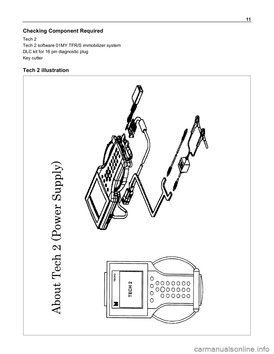
Checking Component Required
Tech 2
Tech 2 software 01MY TFR/S immobilizer system
DLC kit for 16 pin diagnostic plug
Key cutter
Tech 2 illustration
Page 1044 of 1800

12
lmportant information on Programming
Security code
If the immobilizer and engine control unit are replaced at the same time, the immobilizer control unit must be
programmed first before the “IMMOBILIZER” function in the engine control unit can be activated.
The security code protects the immobilizer control unit against unauthorized programming and data access from
Tech 2. The security code consists of a 4 digit code number and is programmed into the immobilizer control unit
and ECM (Engine Control Module; Gas Engine only).
New control units are not programmed with a security code. If the control units are replaced, the security code
entered in the car pass, transponder lD, etc. must be programmed into the new control unit with Tech 2.
The security code can only be programmed with Tech 2 once and must therefore be performed with great care.
Once programmed, the security code cannot be overwritten.
An already used immobilizer can be reused in a different car by initializing the immobilizer.
After that you can program the security code again. For initializing command you need the current security code.
If the immobilizer control unit is returned (e.g. warranty cases), always enclose the security code that is allocated to
that control unit. If this is not done, we can not process the case and the warranty will not be recognized.
1. Entering a code
If the Tech 2 display requests the
security code
mechanical key number
Vehicle Identification No.
to be entered, process as follows;
To input a digit you need to use the up and down buttons of the Tech 2. By using the numeric buttons, the
according digit will be displayed at the current position and the cursor will move to the next position.
For letters you need to use the up and down buttons of the Tech 2. The up and down key might be used for
digits as well. By using the up and down buttons, the displayed digit or letter will be increased or decreased. To
move to the next position you need to use the move-to-right-button.
With the two buttons, move-to-right and move-to-left you can select the position of number you want to change.
This will allow you to correct a wrong number.
After the number is completed you need to press the Enter button to accept the number.
Correction is now no longer possible.
Use the OKAY soft key to program the number and the NOT OKAY soft key to abort the programming.
Page 1045 of 1800
13
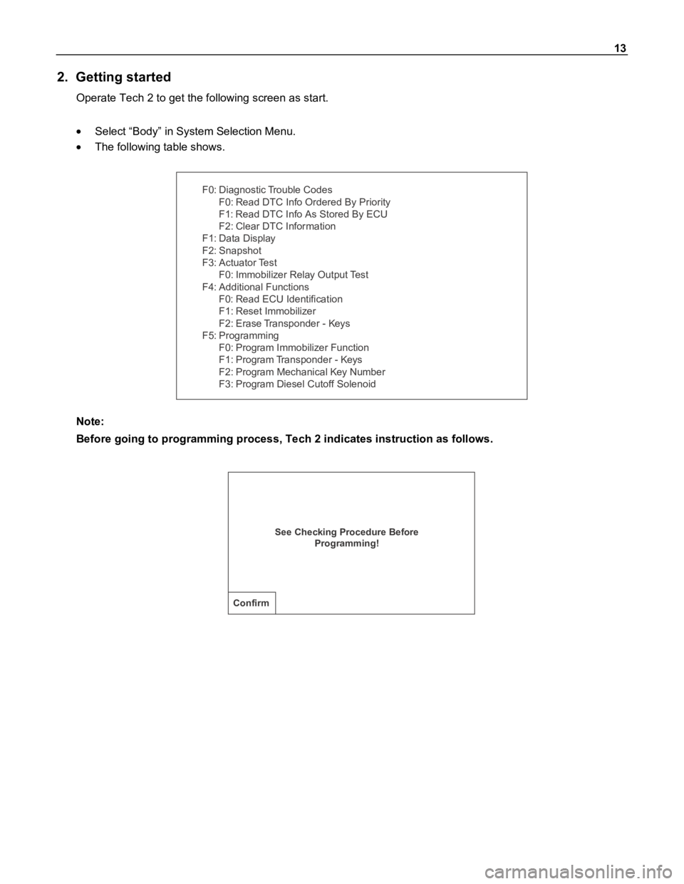
2. Getting started
Operate Tech 2 to get the following screen as start.
Select “Body” in System Selection Menu.
The following table shows.
F0: Diagnostic Trouble Codes
F0: Read DTC Info Ordered By Priority
F1: Read DTC Info As Stored By ECU
F2: Clear DTC Information
F1: Data Display
F2: Snapshot
F3: A c tua tor Te s t
F0: Immobilizer Relay Output Test
F4: Additional Functions
F0: Read ECU Identification
F1: Reset Immobilizer
F2: Erase Transponder - Keys
F5: Programming
F0: Program Immobilizer Function
F1: Program Transponder - Keys
F2: Program Mechanical Key Number
F3: Program Diesel Cutoff Solenoid
Note:
Before going to programming process, Tech 2 indicates instruction as follows.
See Checking Procedure Before
Programming!
Confirm
Page 1046 of 1800
14
3. Transponder
If a transponder key is lost;
All transponder keys in the immobilizer control system must be erased. Transponder keys can be ordered via
the "Your proper organization name such as Parts and accessory department" as previously by providing the
mechanical key number.
The mechanical key number is provided on the car pass.
Thereafter, existing and new transponder keys are programmed consecutively using Tech 2. The vehicle can
then no longer be started using lost key.
5 transponder keys can be provided:
Each transponder has different Identifications. If a customer wants more than 2 transponder keys, maximum to
5 transponder keys can be provided by additional programming by Tech 2.
lf a new ignition key with different mechanical key number needs to be installed;
If installation of an ignition lock with a different mechanism key number is necessary (an ignition lock which
belongs to the mechanical key number has to be ordered first), all transponder keys must first be erased and
the two transponder keys which belong to the ignition lock that is now installed must be programmed.
The new mechanical key number must be programmed now into the immobilizer. The mechanical key number
in the car pass is to be changed as well.
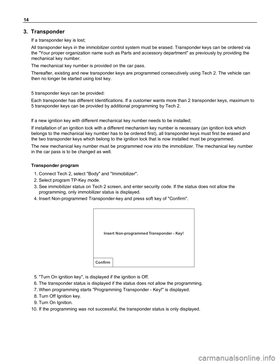
Transponder program
1. Connect Tech 2, select "Body" and "Immobilizer".
2. Select program TP-Key mode.
3. See immobilizer status on Tech 2 screen, and enter security code. If the status does not allow the
programming, only immobilizer status is displayed.
4. Insert Non-programmed Transponder-key and press soft key of "Confirm".
Insert Non-programmed Transponder - Key!
Confirm
5. "Turn On ignition key", is displayed if the ignition is Off.
6. The transponder status is displayed if the status does not allow the programming.
7. When programming starts "Programming Transponder - Key!" is displayed.
8. Turn Off Ignition key.
9. Turn On Ignition.
10. If the programming was not successful, the transponder status is only displayed.
Page 1047 of 1800
15
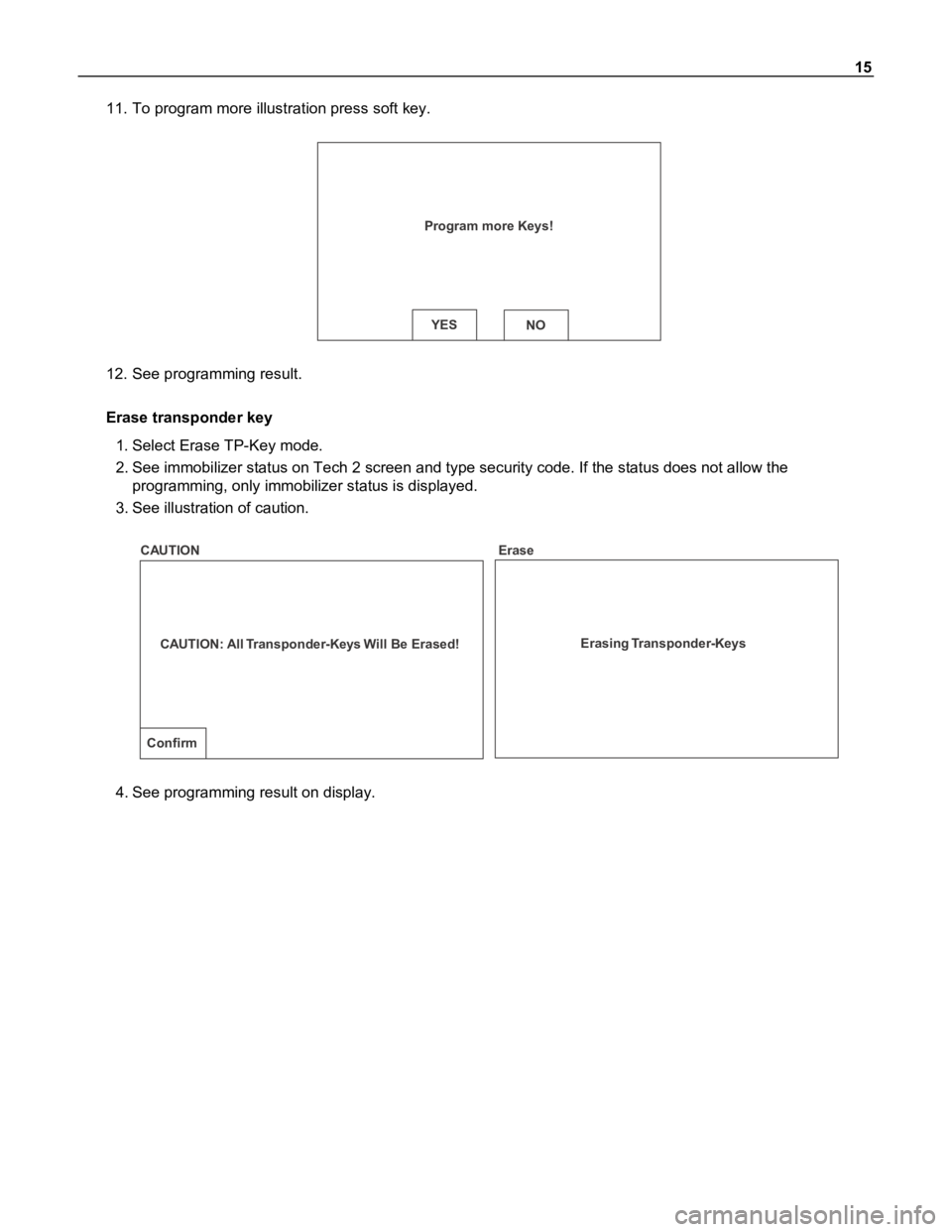
11. To program more illustration press soft key.
Program more Keys!
YESNO
12. See programming result.
Erase transponder key
1. Select Erase TP-Key mode.
2. See immobilizer status on Tech 2 screen and type security code. If the status does not allow the
programming, only immobilizer status is displayed.
3. See illustration of caution.
CAUTION: All Transponder-Keys Will Be Erased!
Confirm
Erasing Transponder-Keys CAUTION Erase
4. See programming result on display.
Page 1049 of 1800
17
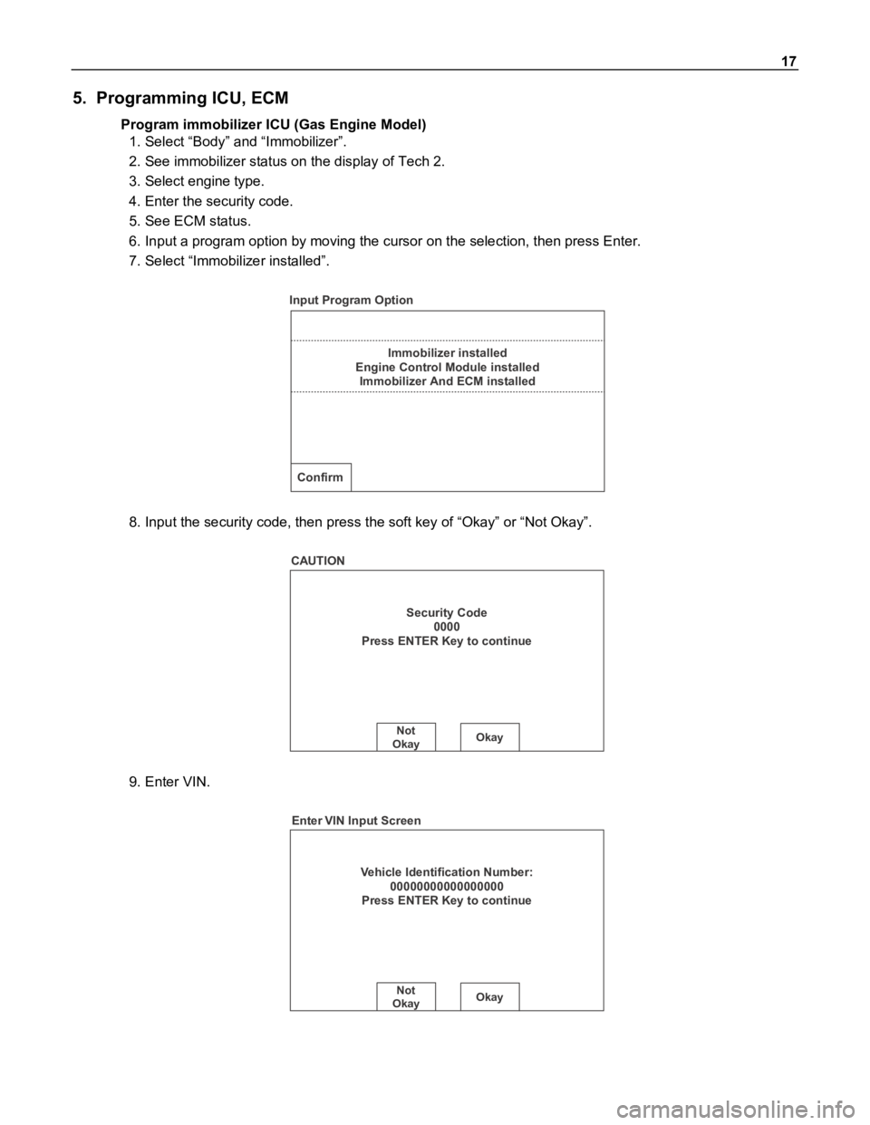
5. Programming ICU, ECM
Program immobilizer ICU (Gas Engine Model)
1. Select “Body” and “Immobilizer”.
2. See immobilizer status on the display of Tech 2.
3. Select engine type.
4. Enter the security code.
5. See ECM status.
6. Input a program option by moving the cursor on the selection, then press Enter.
7. Select “Immobilizer installed”.
Immobilizer installed
Engine Control Module installed
Immobilizer And ECM installed
Confirm
Input Program Option
8. Input the security code, then press the soft key of “Okay” or “Not Okay”.
Security Code
0000
Press ENTER Key to continue
Not
OkayOkay
CAUTION
9. Enter VIN.
Vehicle Identification Number:
00000000000000000
Press ENTER Key to continue
Not
OkayOkay
Enter VIN Input Screen