Page 544 of 1395
Description
Hydraulic Control (cont'd)
Servo Body
The servo body is located on the secondary valve body. The servo body contains the servo valve (which is integrated withthe reverse shift fork), and the accumulators.
2ND ACCUMULATOR
3RD SUBACCUMULATOR
SERVO BODY
1ST ACCUMULATOR
SERVO VALVE/SHIFTFORK SHAFT
14-28
www.emanualpro.com
Page 581 of 1395
From page 14-64
Check Lock-up Control Sol6noidValve A tor a Short Circuit:1. Disconnect the 2P connectorfrom the lock-up control solenoid valve 4!/B assembly.2. Check for continuity betweenthe 85 and A9 or A22 terminals.
Reprir short to ground in the wire
between the 85 terrninal and thelock-uD contiol solenoid valve A.
Measuro Lock-up Control Sole-
noid Valve A Resistance at the
solenoid valve Connector:Measure the resistance betweenthe No. 2 terminal of the connec-
tor and body ground.
Check for open in the wire
belwe€n the 85 teiminal and the
lock-uo control solenoid valve Als the resistance 12 - 25 O?
Replace the lock-np control sole-noid valve A/B assembly.
PCM CONNECTORS
Wire side of female terminals
LOCK.UP CONTROL SOLENOID
VALVE A/B ASSEMBLY CONNECTOR
----E-
lFr].=--
A Lc A IYELI(nJY
t
Terminal side of male terminals
14-65
www.emanualpro.com
Page 583 of 1395
Check Lock-up Control SolenoidValve B lor a Short Circuit:1. Disconnect the 2P connectorfrom the lock-up control solenoid valve A/8 assembly.2. Check for continuity betweenthe 84 and A9 or A22 lermi_nals-
Repair short to ground in the wirebetween the 84 lerminal and the
lock-up conlrol solenoid valve B.
Me6aure Lock-up Control Sole_noid Valve B Resistance at the
Solenoid Valve Connector:Measure the resistance betweenthe No. 1 terminal of the connec-
tor and body ground.
Check lor open in the wire
bctween the 84 terminal and thelock-up control solenoid volva B.ls the resistance 12 - 25 0?
Replace the lock-up conttol sole-noid valve A/B ass6mbly.
From page 14 66PCM CONNECTORS
Wire side of female terminals
LOCK-UP CONTROL SOLENOID
VAI-VE A/B ASSEMBLY CONNECTOR
LC B (GRN/BLK)
14-67
www.emanualpro.com
Page 589 of 1395
From page 14-72
Check Shift Con ol SolenoidValve A for a Short Circuit:1. Disconnect the 2P connectorfrom the shift control solenoidvalve Ay'B assembly.2. Check for continuity betweenthe 83 and A9 orA22terminals.
Repai. short to ground in the wirebelw€en th6 83 terminal and theshift cont.ol solenoid valve A.
Measure Shift Control SolenoidValv6 A Resistance at the SolenoidValve Connector:Measure the resistance betweenthe No. 1 terminal of the connector and body ground.
Check lor ooen in the wirebetween the 83 terminal and theshift control sol€noid valve A.ls the resistance 12 - 25 0?
Replace the shift control solenoidvalve A/B assemblv.
Wire side of female terminals
SHIFT CONTROL SOI.ENOIDVALVE A/B ASSEMALY CONNEC1OR
SH A IBLU/YELI
Terminal side of male terminals
lffil
l--(o)
T
I
14-73
www.emanualpro.com
Page 591 of 1395
From page 14-74
Check Shift Control SolenoidValvo B tor a Short Circuil:1. Disconnect the 2P connectorfrom the shift control solenoidvalve y'y'8 assembly.2. Check for continuity betweenthe 811 and Ag or A22 termi-nals,
Ropair short to ground in the wireb64w€€n tho 811 torminal and lhgshift control solenoid valvo B.
Meesure Shift Control SolenoidValve B Rosistance at lh€ Sole-noid Vrlve Connector:Measure the resistance betweenthe No. 2 terminal ol the connector and body ground.
Check tor open in the wirebdtweon the 811 torminal and theshift control sol€noid valv6 B.ls the resistance 12 - 25 O?
Reolace the shift control solenoidvalve A/B asJembly,
PCM CONNECTORS
Wire side of female terminals
SHIFT CONTROL SOLENOIDVALVE A/B ASSEi'BLY CONNECTOR
ti;Tll
I sH B |GRN/W{T|
o
YII
Terminal side of male terminals
14-75
www.emanualpro.com
Page 610 of 1395

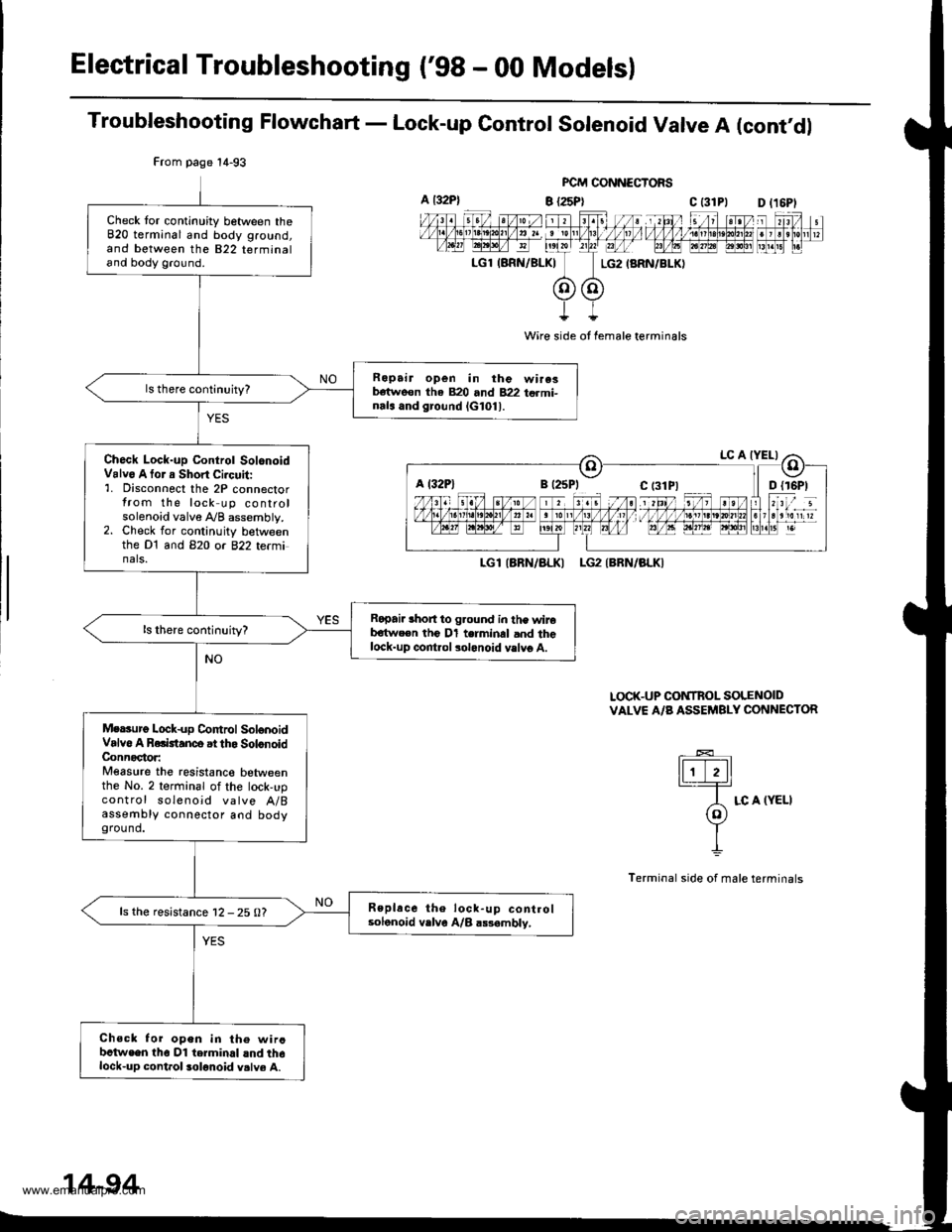
Electrical Troubleshooting ('98 - 00 Models)
Troubleshooting Flowchart - Lock-up Control Solenoid Valve A (cont'dl
FCM CONNECTORS
B {25P} C t31Pl
Wire side ot female terminals
LGlIARN/ALKI LG2IBRN/BLKI
LOCK-UP CONTROL SOLENOIDVALVE A/B ASSEMBLY CONNECTOR
tFttl._T=
A LC A (YELI(o)Y
I
Terminal side of male terminals
From page 14-93
Check tor continuity between theB20 terminal and body ground,and between the 822 terminaland body ground.
Ropair open in the wire3b€tweon tha 820 and 822 termi-nals and ground lG101l.
Ch6ck Lock-up Control SolonoidValv6 A tor a Short Ci.cuit:'1. Disconnect the 2P connectorfrom the lock up controlsolenoid valve A/B assembly.2. Check for continuity betweenthe Dt and B2O or 822 te(minals.
Ropai. lhort to g.ound in the wireb€twe€n the Dl terminal and thelock-up control solonoid vslvg A.
Mersurg Lock-up Co|ttrol SolonoidValvo A Rolktanco at tho SolonoidConnoctor:Measure the resistanco betweenthe No. 2 terminal of the lock,upcontrol soleno;d valve A/Bassembly connector aod bodyground.
Replace the lock-up controlsolonoid vrlve A/B a$ambly,ls the resistance 12 - 25 0?
Chsck for open in th€ wircbctwe€n tho Dl terminal lnd th6lock-up cont.ol solonoid v.lve A.
a t32P)D l16Pl
a l32Plc t3lPl
14-94
www.emanualpro.com
Page 613 of 1395

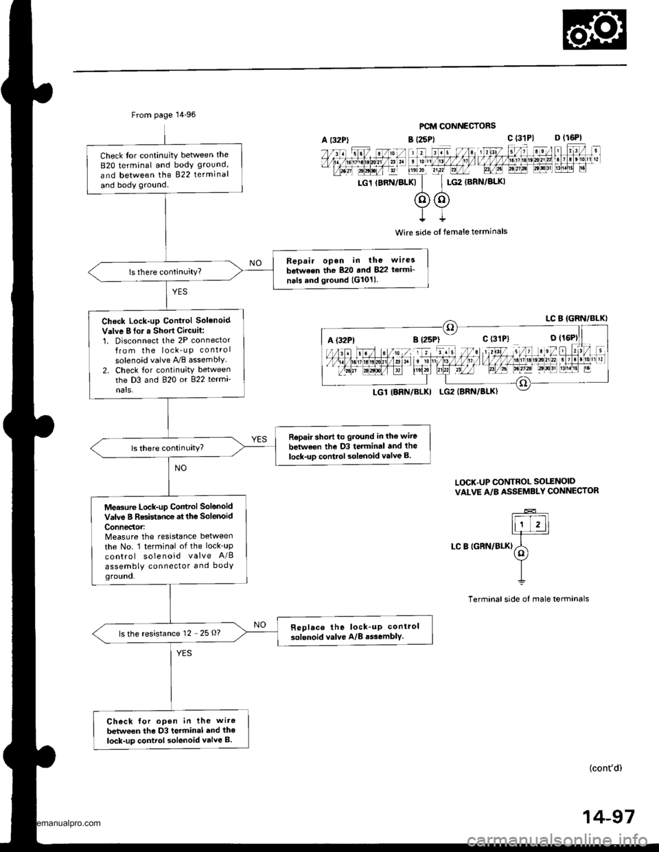
From page 14-96
Check Ior continuity betlveen the
B2O terminal and body ground,
and between the 822 terminal
and body ground.
Bepair open in the wirea
between the 820 and 822 te.mi-
nals and ground (G1011.
Check Lock-up Control Solenoid
Valve I fo. a Short Circuit:1. Disconnect the 2P connectorfrom the lock_u p control
solenoid valve A,/B assembly2. Check for continuity betweenthe D3 and 820 or 822 termi
nats.
Rep.ir short to ground in the wiie
between the D3 terminal and the
lock-uD control solenoid valve B.ls there continuity?
Measure Lock-up Control Solenoid
valve B Resistance at the solenoid
ConnedoMeasure the resistance between
the No. 1 terminal of the lock_up
control solenoid valve A/B
assembly connector and bodYground.
Replace the lock_up conirol
solenoid valve A/8 a$embly.ls the resistance 12 - 25 O?
Check for open in the wiro
betwoen the D3 terminal and the
lock-up control solenoid valve B.
PCM CONNECTORS
B (25Pt c (31P1 D (16P1
rc1 rBRN/BLKk'
c$G2
{BRN/BLKI
t
Wire side ol female terminals
L(rcK.UP CONTROL SO1TNOID
VALVE A/B ASSEMBLY CONNECTOR
LC B IGRN/BLK)
(cont'd)
14-97
A {32P1
www.emanualpro.com
Page 623 of 1395
![HONDA CR-V 1997 RD1-RD3 / 1.G Workshop Manual
A l32Pl
From page 14-106PCM CONNECTORS
B (25P1 C (31
LGl IERN/BLKILG2 {BRN/BLK)
Wire side of female terminals
LGl IBRN/BLK}LG2 (BRN/BLK}
SHIFT CONTROI SOLENOIDVALVE A/B ASSEMBLY CONNECTOR
IiiE-]
"*ot HONDA CR-V 1997 RD1-RD3 / 1.G Workshop Manual
A l32Pl
From page 14-106PCM CONNECTORS
B (25P1 C (31
LGl IERN/BLKILG2 {BRN/BLK)
Wire side of female terminals
LGl IBRN/BLK}LG2 (BRN/BLK}
SHIFT CONTROI SOLENOIDVALVE A/B ASSEMBLY CONNECTOR
IiiE-]
"*ot](/manual-img/13/5778/w960_5778-622.png)
A l32Pl
From page 14-106PCM CONNECTORS
B (25P1 C (31
LGl IERN/BLKILG2 {BRN/BLK)
Wire side of female terminals
LGl IBRN/BLK}LG2 (BRN/BLK}
SHIFT CONTROI SOLENOIDVALVE A/B ASSEMBLY CONNECTOR
IiiE-]
"*otrau/"aalF
I
Termanal side of male terminals
(cont'd)
14-107
c (31P)D {16P)
Check for continuity between the820 terminal and body ground.
and between the 822 terminaland body ground.
Ropair open in the wir.s betweonthe 820 and 822 terminal3 andground (G1011.
Check Shilt Control SolenoidValve A for . Short Circuit:1. Disconnect the 2P connectorfrom the shift control solenoidvalve !y'B assembly.2. Check tor continuity betweenthe D7 and B2O ot 822 tetmi-nals.
Repair short to ground in the wirebe{we€n the D7 terminal and the3hift control solonoid valvo A.ls there continuity?
Measure Shift Control SolenoidValve A Resistance at iheSolenoid Connector:Measure the resistance betweenthe No. I terminal of the shiftcontrol solenoid va lve A/Bassembly connector and bodygrou nd,
Replace the shrft control solenoidvalve A/B assembly.ls the resistance 12 25 Q?
Check for op.n in the wirebetwoon tho D7 terminal and theshift control solenoid valve A.
www.emanualpro.com