1997 HONDA CR-V Control
[x] Cancel search: ControlPage 670 of 1395

Symptom-to-Component Chart
Hydraulic System (cont'd)
SYMPTOMCheck these items on thePROBABLE CAUSE ListCheck these items onthe NOTES Lisr
Shift lever does not operate smoothly.o, JdPFails to shift; stuck in 4th gear.14, 41 , 48
Transmission will not shift into park in E position.6, 38, 61PStall rpm high; all clutch pressures are in specification.40D,K,OLock-up clutch does not disengage.18, 43, 44, 45, 46, 49,50,57
Lock-up clutch does not operate smoothly.14, 40, 43, 44, 45, 46, 49, 50. 57Lock-up clutch does not engage.'t8, 40, 43, 44, 45, 46, 49, 50, 56, 57Vibration in all positions.
No engine braking in I position.59
Shift position indicator does not indicate anv position,6. 38, 60
PROBABLE CAUSE
I 33 Thrust washer worn/damaged
ATF pump worn or binding34Clutch clearance incorrect
Regulator valve stuck or regulator valvespflng wornDrive plate delective or transmission mtsas-sembled
Servo valve stuck5ttTorque converter housing or transmissionhousing bearing worn/damagedMainshaft worn/damaged
Shift cable broken/out of adjustmentATF strainer clogged
7Final gears worn/damaged38Shift cable is worn where it attaches to thetransmission or at the body mountsIOne-way (sprag) clutch worn/damaged
1st gears worn/damaged {2 gears)39Modulator valve stuck10lst clutch defective40Torque converter check valve stuck112nd gears worn/damaged (2 gears)41Foreign material in separator plate't22nd clutch defectiveCPB valve stuck
t53rd clutch defective43Lock-up timing valve stuck144th clutch defective44Lock-up shift valve stucktcReverse gears worn/damaged (3 gears)Lock-up control valve stuck16Excessive ATF46Lock-up clutch Diston defective17Torque converter one-way clutch defective47Shift control solenoid valve A defecttve
18Linear solenoid assemblv defective (,98 - OOmodels)48Shift control solenoid valve B dsfectrve
49Lock-up control solenoid valve A defective'19CPC valve stuckLock-up control solenoid valve B deleqtve20l-2 shift valve stuck51Servo control valve stuck212-3 shift valve stuck52lst accumulator defective3-4 shift valve stuck53Foreign material in 2nd exhaust orifice2nd accumulator defective54Foreign material in 3rd exhaust orifice3rd accumulator defectiveForeign material in 4th exhaust orifice4th accumulator defective56Mainshaft speed sensor defective262nd orifice control valve stuckCountershaft speed sensor defective273-4 orifice control valve stuck583rd sub accumulator defective2aForeign material in main orifice59lst-hold clutch defective29Foreign material in lst orifice60A/T gear position switch defective or out ofadjustment30Foreign material in reverse orifice
31Engine output low61Park gear mechanism defective32Needle bearing worn/damaged
14-154
www.emanualpro.com
Page 672 of 1395

Symptom-to-Com ponent Chart
Hydraulic System (cont'd)
NOTES
See flushing procedure, page l4-264 and 265,
BSet idle rpm in gear to specified idle speed. lf still no good, adjust motor mounts as outlined in enginesection of this manual.
clf the large clutch piston O-ring is broken, inspect the piston groove for rough machining.
Dlf the clutch pack is seized or is excessively worn. inspect the other clutches fot wear, and check the orificecontrol valves, CPC valve, and linear solenoid for free movement.
lf the linear solenoid is stuck, inspect the clutches for wear.
lf the 1-2 shift valve is stuck closed. the transmission will not upshift. lf stuck open, the transmission hasno lst gear.
Hlf the 2nd orifice control valve is stuck, inspect the 2nd and 3rd clutch Dacks for wear.
lf the 3-4 orifice control valve is stuck, inspect the 3rd and 4th clutch packs for wear.
Jlf the clutch pressure control valve is stuck closed. the transmission will not shift out of lst gear.
Klmproper alignment of main valve body and torque converter housing may cause ATF pump seizure. Thesymptoms are mostly an rpm-related ticking noise or a high-pitched squeak.
Llf the ATF strainer is clogged with particles of steel or aluminum, inspect the ATF pump and differentialpinion shaft. lf both are OK and no cause for the contamination is found, replace the torque converter.
Mlf the lst clutch feed pipe guide in the end cover is scored by the mainshaft. inspect the ball bearing forexcessive movement in the transmission housing. lf oK, replace the end cover as it is dented. The o-rinounder the guide is probably worn.
N' Replace the mainshaft if the bushing for the 4th feed pipe is loose or damaged, lf the 4th feed pipe is darrFaged or out of round. replace the end cover.' Replace the mainshaft if the bushing for the l st feed pipe is loose or damaged. lf the 1st feed pipe is dam-aged or out of round, replace it.
oA worn or damaged sprag clutch is mostly a result of shifting the transmission in E!. E, or E positionwhile the wheels rotate in reverse. such as rocking the vehicle in snow.
PInspect the frame for collision damage.
lnspect for damage and wear:
l. Reverse selector gear teeth chamfers.
2. Engagement teeth chamfers of countershaft 4th and reverse gear.
3. Shift fork for scuff marks in center.
4. Differential pinion shaft for wear under pinion gears.
5. Bottom of 3rd clutch for swirl marks.
Replace items 1, 2, 3. and 4 if worn or damaged. lf transmission makes a clicking, grinding, or whirring noise,also replace mainshaft 4th gear, reverse idler gear, and countershaft 4th gear in addition to 1,2, 3, or 4.lf differential pinion shaft is worn, overhaul differential assembly, replace ATF strainer, and thoroughly cjeantransmission, flush torque converter. cooler, and lines,lf bottom of 3rd clutch is swirled and transmission makes gear noise. replace the countershaft and final drivenoear,
Be very careful not to damage the torque converter housing when replacing the main ball bearing. you
may also damage the ATF pump when you torque down the main valve body. This will result in ATF pumpseizure if not detected. Use the Drooer tools.
SInstall the main seal flush with the torque converter housing. lf you push it into the torque converterhousing until it bottoms out, it will block the fluid return passage and result in damage.
www.emanualpro.com
Page 674 of 1395

Road Test
(cont'd)
lgrr or E Position:
Upshift
NOTE:
. Lock-upON:The lock-up control solenoid valve A turns ON.. Lock-up OFF: The lock-up control solenoid valve A turns OFF.
4. Accelerate to about 35 mph (57 km/h) so the transmission is in 4th. then shift from E or E position to E position.The vehicle should immediately begin slowing down from engine braking.
5. Check for abnormal noise and clutch slippage in the following positions.
E {1st Gear) Position
Accelerate from a stop at full throttle, Make sure there is no abnormal noise or clutch slippage.Upshifts should not occur with the shift lever in this position.
E (2nd cear) Position
Accelerate from a stop at fuI throttre. Make sure there is no abnormar noise or crutch srippage.Upshifts and downshifts should not occur with the shift lever in this position.
E (Reverse) Position
Accelerate from a stop at full throttle. and check for abnormal noise and clutch slippage.
6. Test in E (Park) Position
Park the vehicle on slope (approx. 16"), apply the parking brake, and shift into E position. Release the brake; the vehi-cle should not move.
Throftle OpsningUnit of sps€dlsi + 2nd2nd * 3rd3rd + ilthLock-up ON
Throttle position sensor
voltage: 0.75 V
mph9-1220-2328-33
km/h15-1945-5334-40
Throttle position sensor
voltage; 2.25 V
mph22-2643-49oz - ott68-74
km/h35-4169-7999 - 108109 - 118
Fully-opened throttle,
Throttle position sensor
voltage: 4.5 V
mph37-43101 - 11190 - 101
k-/h60-69111 - 124163 - 179145 - 163
Downshift
Throttle OpeningUnit ot speedLock-up OFFi{th + 3rd3rd * 2ndznd + lst
Fully-closed throttle,
Throttle position sensor
voltage; 0.5 V
mpn19-231A - 2'l6 - 10 {3rd - 1st)
km/h5t-5D29-3410 - 15 (3rd * 1st)
Fully-opened throttle,
Throttle position sensor
voltage: 4,5 V
mph88-9986-9657 -6426-32
km/h142 - 't59138 - 15492 - 10342-51
14-158
www.emanualpro.com
Page 678 of 1395

Pressure Testing
(cont'd)
Line Proslure, lst Clutch, lst.hold Clutch prsssuro Measuromont
1. Start the engine, and shift to E or @ position.
2. Run the engine at 2,000 rpm, then measure line pressure. Higher pressure may be indicated if measurements aremade in shift lever positions other than E or @ position.
shift to E ('97 - 98) or E ('99 - oo) position and hold the engine at 2.ooo rpm, then measure 1st clutch pressure.
Shift to E position and hold the engine at 2,000 rpm, then measure lst-hotd ctutch Dressure.
LOCK.UP CONTROLSOLENOID VALVEA/B ASSEMBLY
4.
PRESSURESHIFT LEVER
POSmONSYMPTOMPROBABLE CAUSEFLUID PRESSURE
StandaldService Limit
LineEor@No (or low)
line pressure
Torque converter.
ATF pump, pres-
sure regulator,
torque converter
check valve
830 - 880 kPa(8.5 * 9.0 kgflcm,,
120 - '130 psi)
780 kPa
{8.0 kgf/cm,, 'l10 psi)
1st ClutchE (97 - 98)
E ('se - oo)
No or low 1st
pressurelst Clurch
lst-hold
ClutchtrNo or low lst-
hold pressure1st-hold Clutch
14-162
www.emanualpro.com
Page 681 of 1395

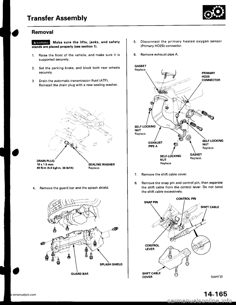
Transfer Assembly
Removal
@ Make sure the lifts, iacks, and safety
stands are placed properly (see section 11.
1. Raise the front of the vehicle, and make sure it is
supported securely.
2. Set the parking brake, and block both rear wheels
securelv.
3 Drain the automatic transmission fluid (ATF).
Reinstall the drain plug with a new sealing washer'
DRAIN PLUG'18 x'1.5 rnm49 N.m 15.0 kgf.m, 36 lbl.ftl
4. Remove the guard bar and the splash shield.
GUARD 8AR
14-165
5.Disconnect the primary heated oxygen sensor
{Primary HO2S) connector.
Remove exhaust pipe A.
SELF-LOCKINGNUTBeplace.
7.
SEI-F.LOCKINGNUTReplace.
NUTReplace
Remove the shift cable cover.
Remove the snap pin and control pin, then separate
the shift cable from the control lever. Do not bend
the shift cable excessively.
(cont'd)
www.emanualpro.com
Page 683 of 1395

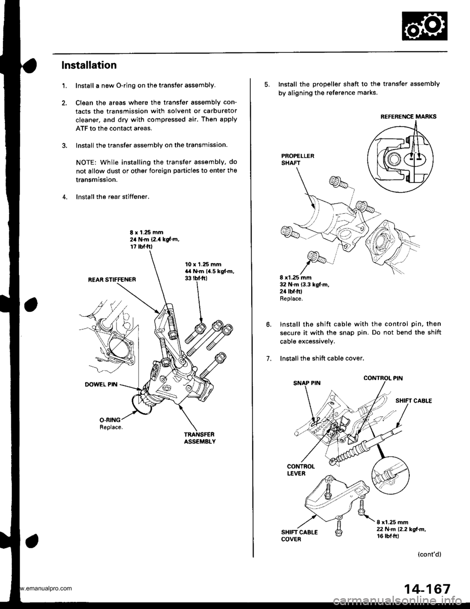
lnstallation
Install a new O-ring on ths transfer assembly.
Clsan the areas where the transfer assembly con-
tacts the transmission with solvent or carburetor
cleaner, and dry with compressed air. Then apply
ATF to the contact areas.
Install the transter assembly on the transmission.
NOTE: while installing the transfer assembly, do
not allow dust or other foreign particles to enter the
transmission.
lnstall the rear stiffener.
1.
8 r 1.25 mm24 N.m {2.4 kgf m,
r7 bl.ftl
TNANSFERASSEMALY
10 x'l.25 mmara N.m 14.5 kgtm,33 tbf trl
O.RING
5. Install the propeller shaft to the transfer assembly
by aligning the reference marks
PROPELLERSHAFT
8 xl,25 ]nm32 N.m (3.3 kgl.m,2a tbf.ftlReplace.
Install the shift cable with the control pin, then
secure it with the snap pin. Do not bend the shift
cable excessively.
lnstallthe shift cable cover.
SHIFT CABLE
7.
8 xl.25 mm22 N.m 12.2 kd-m,16 tbt.ftl
(cont'd)
REFERENCE MARKS
14-167
www.emanualpro.com
Page 685 of 1395

Transmission
Removal
@
2.
'1.
Make sure lifts. iacks, and safety stands aro placed
properly, and hoist brackets are attached to the col-
rest position on the engine lsee section 11.
Apply th€ parking brake and block the r€ar wheels,
so vehicls will noi roll off the stands and fall on you
while working under it.
NOTE: Use fender covers to avoid damaging painted
surfaces.
Disconnect the negative terminal, then disconnect
the positive terminal from the battery.
Remove the intake air duct and the air cleaner hous-
ing assembly,
Remove the starter cables. Remove the harness
clamp from the clamp bracket.
5.
STARTERCABLES
Remove the transmission ground cable terminal
and the radiator hose clamp lrom the transmission
hanger.
Disconnect the lock-up control solenoid valve con-
nector, then remove the harness clamp from the
clamp bracket.HARNESS CLAMP
RADIATOR HOSECLAMP
CONTROLSOLENOID VALVECONNECTOR
CLAMP
6. Disconnect the vehicle speed sensor (VSS), the coun-
tershaft speed sensor, and the A/T gear position
switch connectors.
A/T GEAR POSITIONSWITCH CONNECTOR
VEHICLE SPEEDSENSOR |VSS'
CONNECTORBfiACKET
SPEED SENSORCONNECTOR
7. Remove the transmission housing mounting bolts.
MOUNTING BOLTS
(cont'd)
14-169
www.emanualpro.com
Page 686 of 1395

Transmission
Removal (cont'd)
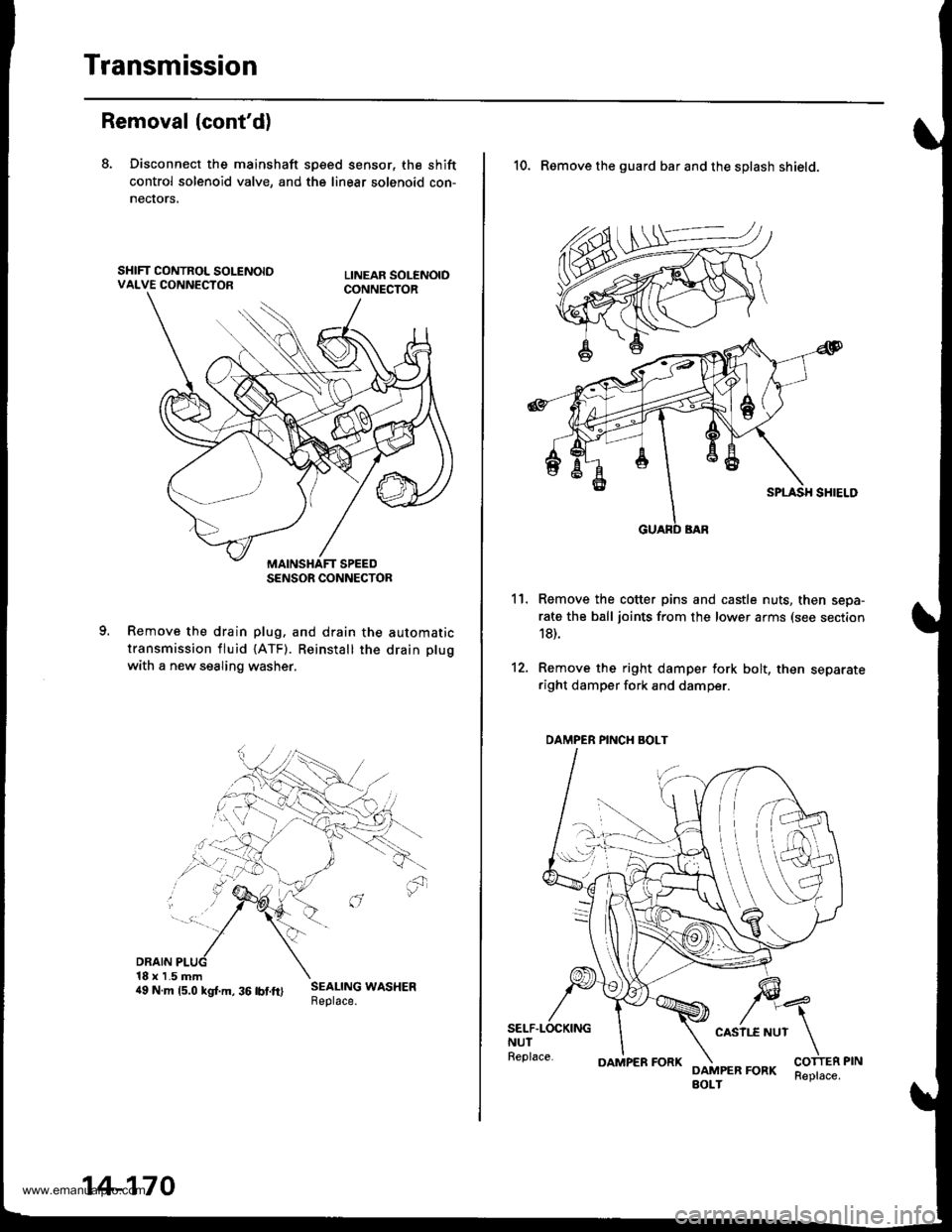
8. Disconnect the mainshaft sp€ed sensor, the shift
control solenoid valve, and the linear solenoid con-
necrors,
Remove the drain plug. and drain the automatic
transmission fluid {ATF). Reinstall the drain plug
with a new sealing washer.
DRAIN18 x 1.5 mm4e N.m rs.o ksr.m. 36 rbrft) ;:i:$: *o"*."
SENSOR CONNECTOR
14-170
OAMPER FORKReplace.
10. Remove the guard bar and the splash shield.
Remove the cotter pins and castle nuts, then sepa-
rate the ball joints from the lower arms (see section
18).
Remove the right damper fork bolt, then separateright damper fork and damper.
11.
12.
SELF.LOCKINGNUTReplace.
CASII.E NUT
DAMPER FORKBOLT
DAMPER PINCH BOLT
www.emanualpro.com