1997 HONDA CR-V Control
[x] Cancel search: ControlPage 652 of 1395

Shift Control Solenoid Valve A/B Assembly
Test
'1. Disconnect the 2P connector from
solenoid valve Ay'B assembly.
the shift control
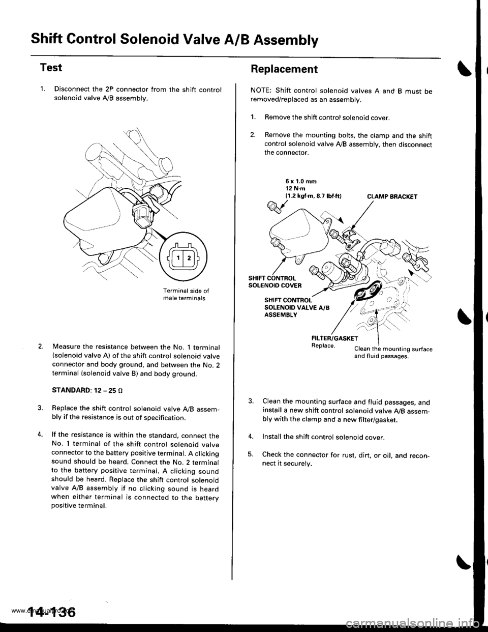
Terminalsade ofmale terminals
Measure the resistance between the No. 1 terminal(solenoid valve A) of the shift control solenoid valve
connector and body ground, and between the No. 2terminal (solenoid valve B) and body ground.
STANDARD: 12 - 25 O
Replace the shift control solenoid valve A,/B assem-bly if the resistance is out of specification.
lf the resistance is within the standard. connect theNo, I terminal of the shift control solenoid valveconnector to the battery positive terminal. A clickingsound should be heard. Connect the No. 2 terminalto the battery positive te.minal. A clicking soundshould be heard. Replace the shift control solenoidvalve A/B assembly if no clicking sound is heardwhen either terminal is connected to the battervpositive terminal.
14-136
Replacement
NOTE: Shift control solenoid valves A and B must beremoved/replaced as an assembly.
1. Remove the shift control solenoid cover.
2. Remove the mounting bolts, the clamp and the shiftcontrol solenoid valve Ay'B assembly, then disconnect
the connector.
6x1.0mm12 N.m{1.2 k9 .m,8.7 lbtft}CLAMP ARACKET
FILTER/GASKETReplace.Clean the mounling surfaceand fluid passages.
Clean the mounting surface and fluid passages. andinstall a new shift control solenoid valve Ay'B assem-bly with the clamp and a new filter/gasket.
Install the shift control solenoid cover.
Check the connector for rust, dirt. or oil, and recon-nect it securely.
w
SHIFT CONTROLSoLENO|O COVEn
SHIFT CONTROLSOLENOID VALVE A/BASSEMBLY
\--
qK
-!t'">,,
www.emanualpro.com
Page 657 of 1395
![HONDA CR-V 1997 RD1-RD3 / 1.G Workshop Manual
8. Set the control shaft to E] position. then install the
A,/T gear position switch on it.
CONTROL SHAFT
Install the AyT gear position switch cover and har-
ness clamp on the end cover.
Connect the HONDA CR-V 1997 RD1-RD3 / 1.G Workshop Manual
8. Set the control shaft to E] position. then install the
A,/T gear position switch on it.
CONTROL SHAFT
Install the AyT gear position switch cover and har-
ness clamp on the end cover.
Connect the](/manual-img/13/5778/w960_5778-656.png)
8. Set the control shaft to E] position. then install the
A,/T gear position switch on it.
CONTROL SHAFT
Install the Ay'T gear position switch cover and har-
ness clamp on the end cover.
Connect the A,/T gear position switch connector.
then install it on the connector bracket.
Turn the ignition switch ON (ll). Move the shift lever
through all gears, and check the AfI gesr position
switch synchronization with the A/T gear position
indicator.
9.
10.
11.
A/TGEARPOSMON A/T GEAR POSITIONINDICATOR INDICATOR'99 - 00 MODELS '�97 - 98 MOOELS
12, Start the engine. Move the shift lever through all
gears. and verify the following:
. The shift lever cannot be moved to E] position
from E position unless the shift lever is pulled.
. The engine will not start in any position other
than E or E.. The back-up lights come on when the shift lever
is in El position.
14-141
www.emanualpro.com
Page 658 of 1395

A/T Gear Position Indicator
1.
f nput Test -'97 - 98 Models
Remove the gauge assembly from the dashboard (see section 20). and disconnect the 14P connector from the gauge
assemblv (see section 23),
Inspect the connector and socket terminals to be sure they are all making good contact.
. lf the terminals are bent, loose, or corroded, repairthem as necessary, and recheck the system.. lf the terminals look OK, make the following input tests at the 14P connector.- lf I test indicates a problem, find and correct the cause, then recheck the system.- lf all the input tests prove OK, but the indicator is faulty. replace the printed circuit board,
GAUGE ASSEMBLY 14P CONNECTOR
Wire side of female terminals
CavityWirs
ColorTest ConditionTest: Desir€d ResultPossible Cause
{lf rosult is not obtainod)
YEL
lgnition switch ON (ll)Check for voltage to ground:
There should be battery voltage,
. Blown No. 25 (7.5 A) fuse in the
under-dash fuse/relay box. An open in the wire
RE D/BLKCombination light
switch ON and dash
lights brightness con-
trol dial on full bright
Check for voltage between No. 2
and No. 3 terminals;
There should be battery voltage.
Blown No. 47 (7.5 A) fuse in the
under-dash fuse/relay box
Faulty combination Iight switch
Faulty dash iight brightness
controller
An open in the wire
RED
4BLUShift lever in ECheck for continuity to ground:
There should be continuity.
NOTE: There should be no continu-
ity in any other shift lever position.
' Faulty Ay'T gear position switch. An open in the wireBRNShift lever in E
7YELShift lever in @
8BLKUnder all conditionsCheck for continuity to ground:
There should be continuity
. Poor ground {G401). An open in the wire
9GRN/BLK
lgnition switch ON {ll)
and shift lever in any
position except E
Check for voltage to ground:
There should be battery voltage
for two seconds after the ignition
switch is turned ON {ll), and less
than 1 V two seconds later,
' Faulty PCM. An open in the wire
10GRNShift lever in ECheck for continuity to ground:
There should be continuity.
NOTE: There should be no conti-
nuity in any other shift lever posi-
UOn.
. Faulty A,ff gear position switch. An open in the wire1'lREDShift lever in @
12WHTShift lever in E
BLVBLU
Shift lever in ENOTE: Do not push
the brake pedal.
14LT GRN
lgnition switch ON { ll)
and shift lever in any
position except E and
E
Check for voltage to ground:
There should be about 5 V.
. Faulty PCM. An open in the wire
14-142
www.emanualpro.com
Page 659 of 1395

L
Input Test -'99 - 00 Models
Remove the gauge assembly from the dashboard {see section 20), and disconnect the 14P connector from the gauge
assembly (see section 23).
Inspect the connector and socket terminals to be sure they are all making good contact.
a lf the terminals are bent. loose, or corroded. repair them as necessary. and recheck the system.
. lf the terminals look OK, make the following input tests at the 14P connector.- lf a test indicates a problem, find and correct the cause, then recheck the system.- lf all the input tests prove OK, but the indicator is faulty, replace the printed circuit board.
GAUGE ASSEMBLY 14P CONNECTOR
Wire side of female terminals
CavityWire
ColorTest ConditionTest: Desired ResuhPossible Caus6
{lf resutt is not obtainod)
1YEL
lgnition switch ON (ll)Check for voltage to ground:
There should be battery voltage.
. Blown No.25 (7.5 A) fuse in the
under-dash fuse/relay box. An open in the wire
2RE D/BLK
Combination light
switch ON and dash
lights brightness con-
trol dial on full bright
Check for voltage between No. 2
and No.3 terminals:
There should be battery voltage.
Blown No. 47 {7.5 A) fuse in the
under-dash fuse/relay box
Faulty combination light switch
Faulty dash light brightness
controller
An open in the wire
5RED
BRNShift lever in ECheck for continuity to ground:
There should be continuity.
NOTE: There should be no continu-
ity in any other shift lever position.
. Faulty A/T gear position switch. An open in the wire7YELShift lever in E
'10BLUShift lever in E
LT BLU
lgnition switch ON (ll),
shift lever in E. and
Over-Drive is OFF bypressing O/D switch.
Check for continuity to ground:
There should be continuity.
Faulty O/D switch
Faulty A/T gear position switch
Faulty PCM
An open in the wire
8BLKUnder all conditionsCheck for continuity to ground:
There should be continuity
. Poor ground (G401)
. An open in the wire
9a:FI\|/Et| ta
lgnition switch ON (ll)
and shift lever in any
position except E
Check for voltage to groundl
There should be battery voltage
for two seconds after the ignition
switch is turned ON (ll). and less
than 1 V two seconds later.
. Faulty PCM. An open in the wire
11REDShift lever in SCheck for continuity to ground:
There should be continuity.
NOTE: There should be no conti-
nuity in any other shift lever posi-
Iton.
. Faulty A/T gear position switch. An open in the wire12WHTShift lever in E
BLI(BLU
Shift lever in ENOTE: Do not push
the brake pedal.
14LT GRN
lgnition switch ON (ll)
and shift lever in any
position except E and
E
Check for voltage to groundl
There should be about 5 V,
. Faulty PCM. An open in the wire
14-143
www.emanualpro.com
Page 660 of 1395

Interlock System
Interlock Control Unit Input Test
SRS components are located in this area. Review the SRS component locations, precautions, and procedures in the SRS
section (24) before performing repairs or service.
'1. Remove the instrument panel lower cover (see section 20).
2. Disconnect the 8P connector from the interlock control unit.
3. Inspect the connector and connector terminals to be sure they are all making good contact.
. lf the terminals are bent, loose, or corroded, repair them as necessary, and recheck the system
. lf the terminals look OK, make the following input tests at the connector.
- lf a test indicates a problem, find and correct the cause, then recheck the system
- lf all the input tests prove OK, substitute a known-good control unit, and recheck the system. lf the check is OK,
the control unit must be faulty; replace it.
NOTE: lf the shift lock solenoid clicks when the ign ition switch is tu rned ON (ll) while pressing the brake pedal withthe
shift lever in E position, the shift lock system is OK. lf the shift lever cannot be shifted from E position. test the A/T
gear position switch.
14-144
www.emanualpro.com
Page 661 of 1395

1?
4678
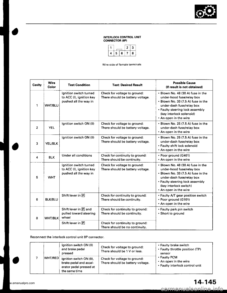
CavityWire
ColorTest CondhionTost: Desired RosultPossible Cause(lf result is not obtainedl
1WHT/BLU
lgnition switch turned
to ACC (l), ignition key
pushed all the way in
Check for voltage to ground:
There should be battery voltage.
Blown No. 48 {30 A} fuse in the
under-hood fuse/relay box
Blown No.33 (7.5 A) fuse in the
under-dash fuse/relay box
Faulty steering lock assembly
{key interlock solenoid)
An open in the wire
YEL
lgnition switch ON (ll)Check for voltage to ground:
There should be battery voltage.
Blown No.25 (7.5 A) fuse in the
under-dash fuse/relay box
An open in the wire
YEUBLK
lgnition switch ON (ll)Check for voltage to ground:
There should be baftery voltage.
Blown No. 25 (7.5 A) fuse in the
under-dash fuse/relay box
Faulty shift lock solenoid
An open in the wire
4BLKUnder all conditionsCheck for continuity to ground:
There should be continuity.
. Poor ground (G401)
. An open in the wire
5WHT
lgnition switch turned
to ACC (l), ignition key
pushed all the way in
Check for voltage to ground:
There should be battery voltage.
Blown No.48 (30 A) fuse in the
under-hood fuse/relay box
Blown No. 33 (7.5 A) fuse in the
under-dash fuse/relay box
Faulty steering lock assembly(key interlock switch)
An open in the wire
BLI(BLU
Shift lever in ECheck for continuity to ground:
There should be continuity,
Faulty Ay'T gear position switch
Poor ground (G101)
An open in the wire
8WHT/BLK
Shift lever in @ and
pulled toward steering
wneel
Check for continuity to ground:
There should be continuity.
Faulty park pin switch
Shon to ground
Shift lever in ECheck for continuity to ground:
There should be no continuity.
Wire side of female terminals
Reconnect the interlock control unit 8P connector.
14-145
7WHT/RED
lgnition switch ON (ll)
and brake pedal
presseo
Check for voltage to ground:
There should be 1 V or less.
Faulty brake switch
Faulty throttle position (TP)
sensor
Faulty PCM
An open in the wire
Faulty interlock control unit
lgnition switch ON (lll,
brake pedal and accel-
erator pedal pressed at
the same time
Check for voltage to ground:
There should be baftery voltage,
www.emanualpro.com
Page 666 of 1395

Interlock System
Park Pin Switch Replacement -'97 - 98 Models
SRS components are located in this area. Review the SRS component locations, precautions, and procedures in the SRS
section (24) before performing repairs or service.
1. Remove the instrument Danel lower cover (see section 20).
2. Remove the upper and lower steering column covers (see section li,.
3. Remove the flange nuts and bolts securing the steering column. then lower the steering column.4. Disconnect the shift lock solenoid and the park pin switch connectors.
5. Remove the harness clamp bracket.
6. Remove the bolts secu ring the shift lever assembly, then removetheshift lever assembly.
7. Remove the screws securing the shift lock solenoid. then remove the shift lock solenoid,
8. Remove the parkpin switch connector from the shift lever control bracket.
9. Remove the control checker from the shift lever control bracket.
10. Remove the park Din switch from the control checker.
PARK PIN SWITCH
PARK PINSWITCH CONNECTOR
scnEw2.5 N m 10.25 kgt.m, 1.8 lbtftl
9.3 N.m 10.95 kgf.m, 6.9 lbl.ft)
BRACKETCONTROL CHECKER
11. Install the new Dark Din switch on the control checker.
12. lnstall the control checker on the shift lever control bracket.
13. Routethe park pin switch harness through thecutoutofthe shift lever control bracket, then install the park pin switchconnector on the bracket.
14. Install the sh ift lock solenoid by a ligning the joint of the sh ift lock solenoid plu nger with the tip of the shift lock exten-sion.
15. Secure the shift lock solenoid with the screws.
15. Install the shift lever assembly in the reverse order of the removal.'17. Check the operation of the shift lever and the shift lock.
14-150
www.emanualpro.com
Page 667 of 1395

Park Pin Switch - Over-Drive (O/Dl Switch Replacement -'99 - 00 Models
SRS components are located in this area. Review the SRS component locations, precautions, and procedures in the SRS
section {24) before performing repairs or service.
NOTE: lf replacement of the park pin switch or the O/D switch is required. replace them as a set.
1. Remove the instrument panel lowercover(see section 20).
2. Remove the upper and lower steering column covers (see section 17).
3. Remove the flange nuts securing the steering column. then lower the steering column.
4. Disconnect the shift lock solenoid and the park pin switch - O/D switch connectors
5. Remove the harness clamp bracket.
6. Remove the bolts securing the shift lever assembly, then remove the shift lever assembly.
7. Remove the screws securing the shift lock solenoid, then remove the shift lock solenoid.
8. Cut the O/D switch wires (REDand BLK),then remove the con nector from the shift lever control bracket
9. Remove the control checker from theshift lever control bracket
10. Remove the oark oin switch from the control checker.
11. Remove the shift lever knob from the shift lever, then remove the O/D switch from the shift lever knob.
SCREW2.5 N.m 10.25 kgtm, 1.8lbf,ft)SHIFT LEVER CONTROLBRACKET
PARK PIN SWITCH -
o/D swlTcHCONNECTOR
2.5 N.m (0.25 kgt m,1.8 tbf.fr)
HABNESS CLAMP BRACKET
9.3 N.m 10.95 kgl.m.6.9 tbf ft)
SHIFT LEVER KNOB6-12N,m{0.6 - 1.2 kgt.m.4 - 8.7 lbf ftl
SHIFT LEVERo/o swlTcH
12. Route the new O/D switch wires through the shift lever knob, shift lever, and shift lever control bracket, then install
the knob on the shift lever, and install the switch in the knob.
13. Install the new park pin switch on the control checker, then install the control checker on the shift lever control brack-
et.
14. Routethe parkpin switch harnessthroughthecutoutoftheshift lever control bracket.
15. Install the O/D switch wire terminals in the connector cavities securely. The wire terminals can be installed in cavity
No. 1 or No.2.
16, Install the connector and the harness clamp on the bracket.
17. tnstall the shift lock solenoid by aligning the joint ot the shift lock solenoid plu nger with the tip of the shift lock exten-
sion, then secure the shift lock solenoid with the screws,
18. lnstall the shift lever assemblv inthe reverse order of removal.
19. Adjust the clearance between the O/D switch wires and the edge of the sh ift lever control bracket (see page 14-270).
20. Check the shift lever operation and shift lock operation.
14-151
www.emanualpro.com