1997 HONDA CR-V Water
[x] Cancel search: WaterPage 13 of 1395
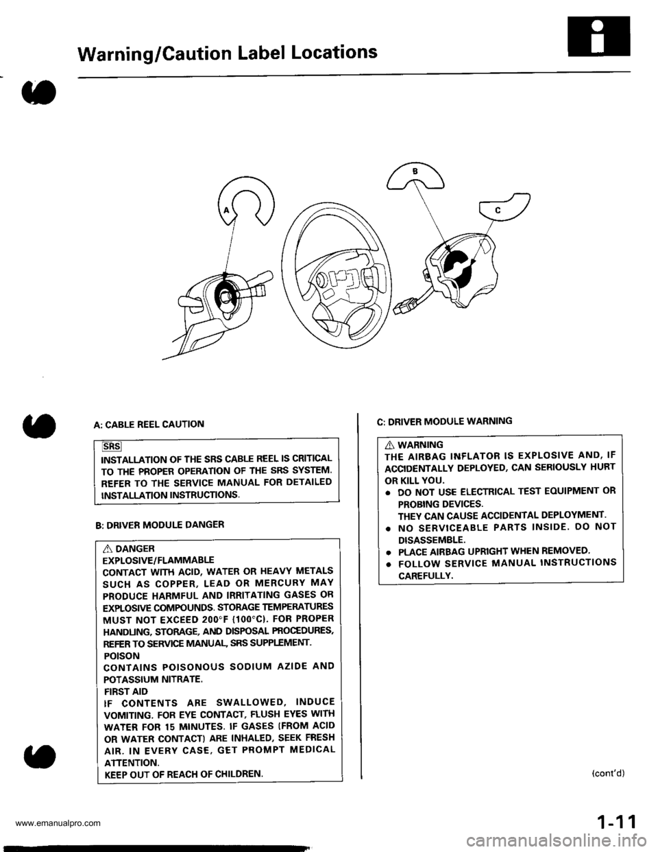
Warning/Caution Label Locations
C: DRIVER MODULE WARNING
A WARNING
THE AIREAG INFLATOR IS EXPLOSIVE AND, IF
ACCIDENTALLY DEPLOYED, CAN SERIOUSLY HURT
OR KILL YOU.
. DO NOT USE ELECTRICAL TEST EOUIPMENT OR
PROBING DEVICES.
THEY CAN CAUSE ACCIDENTAL DEPLOYMENT.
. NO SERVTCEABLE PARTS lNSlDE. DO NOT
DISASSEMBLE.
. PLACE AIRBAG UPRIGHT WHEN REMOVED
. FOLLOW SERVICE MANUAL INSTRUCTIONS
CAREFULLY.
A: CABLE REEL CAUTION
TNSTALLATION OF THE SRS CABLE REEL IS CRITICAL
TO THE PBOPER OPERATION OF THE SRS SYSTEM.
REFER TO THE SERVICE MANUAL FOR DETAILED
INSTALLATION INSTRUCTIONS.
(cont'd)
1-11
B: DRIVER MODULE DANGER
A DANGER
EXPLOSIVE/FLAMMABLE
CONTACT WITH ACID, WATER OR HEAVY METALS
SUCH AS COPPER, LEAD OR MERCURY MAY
PRODUCE HARMFUL AND IRRITATING GASES OR
EXPLOSIVE COMPOUNDS. STOMGE TEM PERATURES
MUST NOT EXCEED 2OO"F {1OO'C}. FOR PROPER
HANDUNG, STORAGE, AND DISPOSAL PROCEDURES.
REFER TO SERVICE MANUAI- SRS SUPPI.EMENT,
POTSON
CONTAINS POISONOUS SODIUM AZIDE AND
POTASSIUM NITRATE.
FIRST AID
tF CONTENTS ARE SWALLOWED, INDUCE
VOMITING. FOR EYE CONTACT, FLUSH EYES WITH
WATER FOR 15 MINUTES. IF GASES IFROM ACID
OR WATER CONTACTI ARE INHALED, SEEK FRESH
AIR. IN EVERY CASE, GET PROMPT MEDICAL
ATTENTION.
KEEP OUT OF REACH OF CHILDREN
www.emanualpro.com
Page 15 of 1395
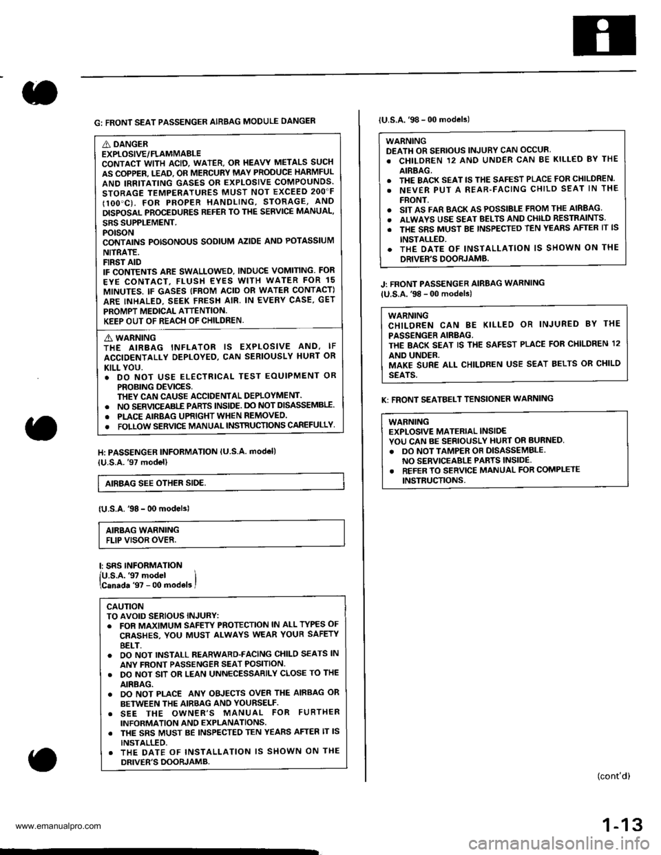
G: FRONT SEAT PASSENGER AIRBAG MODULE DANGEN
A DANGEREXPLOSIVE/FLAMMABLECONTACT WITH ACID, WATER. OR I{EAVY METALS SUCH
AS COPPER. T.EAD. OR MERCURY MAY PRODUCE HARMFUL
AND IRRITATING GASES OR EXPLOSIVE COMPOUNDS.
STORAGE TEMPERATURES MUST NOT EXCEED 2OO"F
IlOO'C). FOR PROPER HANDLING, STORAGE, AND
DISPOSAL PROCEDURES REFER TO THE SERVICE MANUAL,
SRS SUPPLEMENT.POTSONCONTAINS POTSONOUS SODIUM AZIDE ANO POTASSIUM
NITRATE.FIRST AIDIF CONTENTS ARE SWALLOWED, INDUCE VOMITING. FOR
EYE CONTACT, FLUSH EYES WITH WATER FOR 15
MINUTES. IF GASES (FROM ACID OR WATEN CONTACT)
ARE INHALEO. SEEK FRESH AIR. IN EVERY CASE, GET
PROMPT MEDICAL ATTENTION.KEEP OUT OF REACH OF CHILDREN.
A WARNINGTHE AIRBAG INFLATOR IS EXPLOSIVE AND, IF
ACCIDENTALLY DEPLOYED, CAN SERIOUSLY HURT OR
KILL YOU.. DO NOT USE ELECTRICAL TEST EOUIPMENT OR
PROBING DEVICES,THEY CAN CAUSE ACCIDENTAL DEPLOYMENT.. NO SERVICEABI-E PARTS lNSlDE. DO NOT DISASSEMBII.
. PLACE AIRBAG UPRIGHT WHEN REMOVEO.
. FOLLOW SERVIC€ MANUAL INSTRUCTIONS CAREFULLY
H: PASSENGER INFORMATION lU S.A. modell
{U.S.A.'97 model}
AIEBAG SEE OTHER SIDE,
{U.S.A.'98 - 00 modelsl
AIRBAG WARNINGFLIP VISOR OVER.
l: SRS INFORMATION
lU.s.A.'97 model ilcanada '97 - 00 mod€ls I
CAUTIONTO AVOID SERIOUS INJURY:. FOR MAXIMUM SAFEW PROTECTION lN ALL TYPES OF
CRASHES, YOU MUST ALWAYS WEAR YOUR SAFETY
8ELT.o OO NOT INSTALL REARWARD-FACING CHILO SEATS lN
ANY FRONT PASSENGER SEAT POSITION.. DO NOT SIT OR LEAN UNNECESSARILY CLOSE TO THE
AIRBAG.. DO NOT PLACE ANY OBJECTS OVER THE AIRBAG OR
BETWEEN THE AIRBAG AND YOURSELF.. SEE THE OWNER'S MANUAL FOR FURTHER
INFORMATION AND EXPLANATIONS. THE SRS MUST BE INSPECTED TEN YEARS AFTER lT lS
INSTALLED.. THE DATE OF INSTALLATION lS SHOWN ON THE
DRIVER'S DOORJAMB.
lU.S.A.'98 - 00 models)
WARNINGDEATH OR SERIOUS INJURY CAN OCCUR'
. CHILDREN 12 ANO UNDER CAN BE KILLED BY THE
AIRBAG.. THE BACK SEAT lS THE SAFEST PLACE FOR CHILDREN.
. NEVER PUT A REAR-FACING CHILD SEAT lN THE
FRONT.o SIT AS FAR BACK AS POSSIBLE FROM THE AIRBAG
. ALWAYS USE SEAT BELTS AND CHll-D RESTRAINTS.
. THE SRS MUST BE TNSPECTED TEN YEAnS AFTER lT lS
INSTALLED.. THE OATE OF INSTALLATION lS SHOWN ON THE
DRIVER'S DOORJAMB.
J: FRONT PASSENGER AIRBAG WARNING
lU.S.A.'98 - 00 models)
WARNINGCHILDREN CAN BE KILLED OR INJURED 8Y THE
PASSENGER AIRBAG.THE BACK SEAT IS THE SAFEST PLACE FOR CI{ILDREN 12
AND UNDER.MAKE SURE ALL CHILDREN USE SEAT BELTS OR CHILD
SEATS.
K: FRONT SEATBELT TENSIONER WARNING
WABNINGEXPLOSIVE MATERIAL INSIDEYOU CAN BE SERIOUSLY HURT OR BURNED,
. DO NOT TAMPER OR DISASSEMBLENO SERVICEABLE PARTS INSIDE.. REFER TO SERVICE MANUAL FOR COMPLETE
INSTRUCTIONS.
(cont'd)
1-13
www.emanualpro.com
Page 37 of 1395
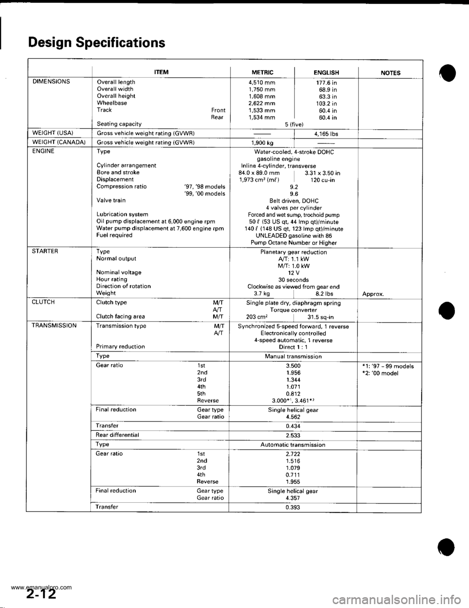
Design Specifications
ITEMMETRICENGLISHNOTES
DIMENSIONSOverall lengthOverallwidthOverall heightWheelbaseTrack FrontRearSeating capacity
4,510 mm1,750 mm1,608 mm2,622 mrn1,533 mm1,534 mm5lf
177.6 in68.9 in63.3 in103.2 in60.4 in60.4 in
WEIGHT (USA)Gross vehicle weight rating (GVWR)| 4,165 tbs
WEIGHT (CANADA)Gross vehicle weight rating (GVWR)1,900 kg
ENGINEType
Cylinder arrangementBore and strokeDisplacementCompression ratio '97,'98 mooers'99, '00 modelsValve train
Lubrication systemOil pump displacement at 6,000 engine rpmWater pump displacement at 7,600 engine rpmFuel required
Water-cooled, 4-stroke DOHCgasoline engineInline 4-cylinder, transverse84.0 x 89.0 mm.1,973 cm3 (m{)
9.2
3.31 x 3.50 in120 cu-in
9.6Belt driven, DOHC4 valves per cylinderForced and wet sump, trochoid pump501 (53 US qt,44 lmp qt)/minute1401 (148 US qt, 123 lmp qt)/minuteUNLEADED gasoljne with 86Pump Octane Number or Higher
STARTERTypeNormal output
NominalvohageHour ratingDirection of rotationWeight
Planetary gear reductionA/T: 1.1 kWM/T: 1.0 kW12V30 secondsClockwise as viewed from gear end3.7 kg 8.2 lbsApprox.
CLUTCHClutch type
Clutch lacing area
MIT
MIT
Single plate dry, diaphragm springTorque converter203 cm, 31.5 sq-in
TRANSMISSIONTransmission type
Primary redLrction
MITSynchronized s-speed torward, 1 reverseElectronically controlled4-speed automatic, 1 reverseDirect I : 1
TypeManualtransmission
Gear ratio 1st2nd3rd4th5thReverse
3.5001.9561.3441.0710.8123.000*,. 3.461*'
*1: '97 - 99 models*2: '00 model
Final reduction Gear typeGear rataoSingle helical gear4.562
Transfer0.434
Rear differential2.533
TypeAutomatic transmission
Gear ratio 1st2nd3rd4thReverse
2.722
1.0790.7111.955
Final reduction Gear typeGear ratioSingle helical gear4.357
Transfer0.393
2-12
www.emanualpro.com
Page 125 of 1395
Timing Belt
Installation (cont'd)
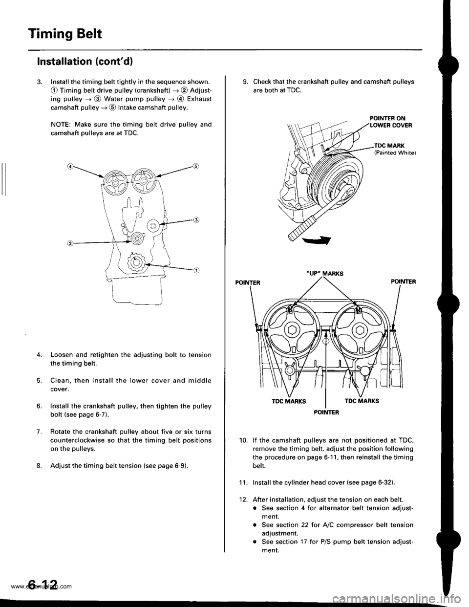
3. Install the timing belt tightly in the sequence shown.
O Timing belt drive pulley (crankshaft) J @ Adjust-
ing pulley =r @ Water pump pulley r @ Exhaust
camshaft pulley --) @ Intake camshaft pulley.
NOTE: Make sure the timing belt drive pulley and
camshaft pulleys are at TDC.
4. Loosen and retighten the adjusting bolt to tension
the timing belt.
5. Clean. then install the lower cover and middle
cover.
Install the crankshaft pulley, then tighten the pulley
bolt (see page 6-7).
Rotate the crankshaft pulley about five or six turns
counterclockwise so that the timing belt positions
on the pulleys.
Adjust the timing belt tension {see page 6-9).
1.
6-12
9. Check that the crankshaft pulley and camshaft pulleys
are both at TDC.
POINTER ON
lf the camshaft pulleys are not positioned at TDC,
remove the timing belt. adjust the position following
the procedure on page 6-11. then reinstall the timing
belt.
Installthe cylinder head cover (see page 6-32).
After installation, adjust the tension on each belt.
. See section 4 for alternator belt tension adjust-
menr.
. See section 22 for NC compressor belt tension
adjustment.
. See section 17 for P/S pump belt tension adjust-
ment.
10.
11.
12.
POINTER
www.emanualpro.com
Page 132 of 1395

13. Remove the upper radiator hose, heater hose and
water bypass hose.
WATER BYPASS
UPPEBRADIATORHOSE
17
HEATERHOSE
Remove the engine wire harness connectors and
wire harness clamps from the cylinder head and the
intake manifold.
o Four fuel injector connectors
. Engine coolant temperature (ECT) sensor con-
neclor
. Radiator fan switch connector
. Coolant temperature gauge sendlng unlt connec-
tor
. Throttle position sensor connector
. Manifold absolute pressure {MAP) sensor con-
nector
Primary heated oxygen sensor (primary HO2S)
connector
ldle air control (lAC) valve connector
Distributor connector
Remove the spark plug caps and distributor from the
cylinder head.
Remove the cruise control actuator (see section 4).
Support the engine with a jack, then remove the
upper bracket. Make sure to place a cushion
between the oil pan and the iack (see page 6-10).
a
18. Remove the cylinder head cover.
19. Inspect the timing belt (see page 6-9).
CYLINDER
(cont'd)
6-19
www.emanualpro.com
Page 134 of 1395
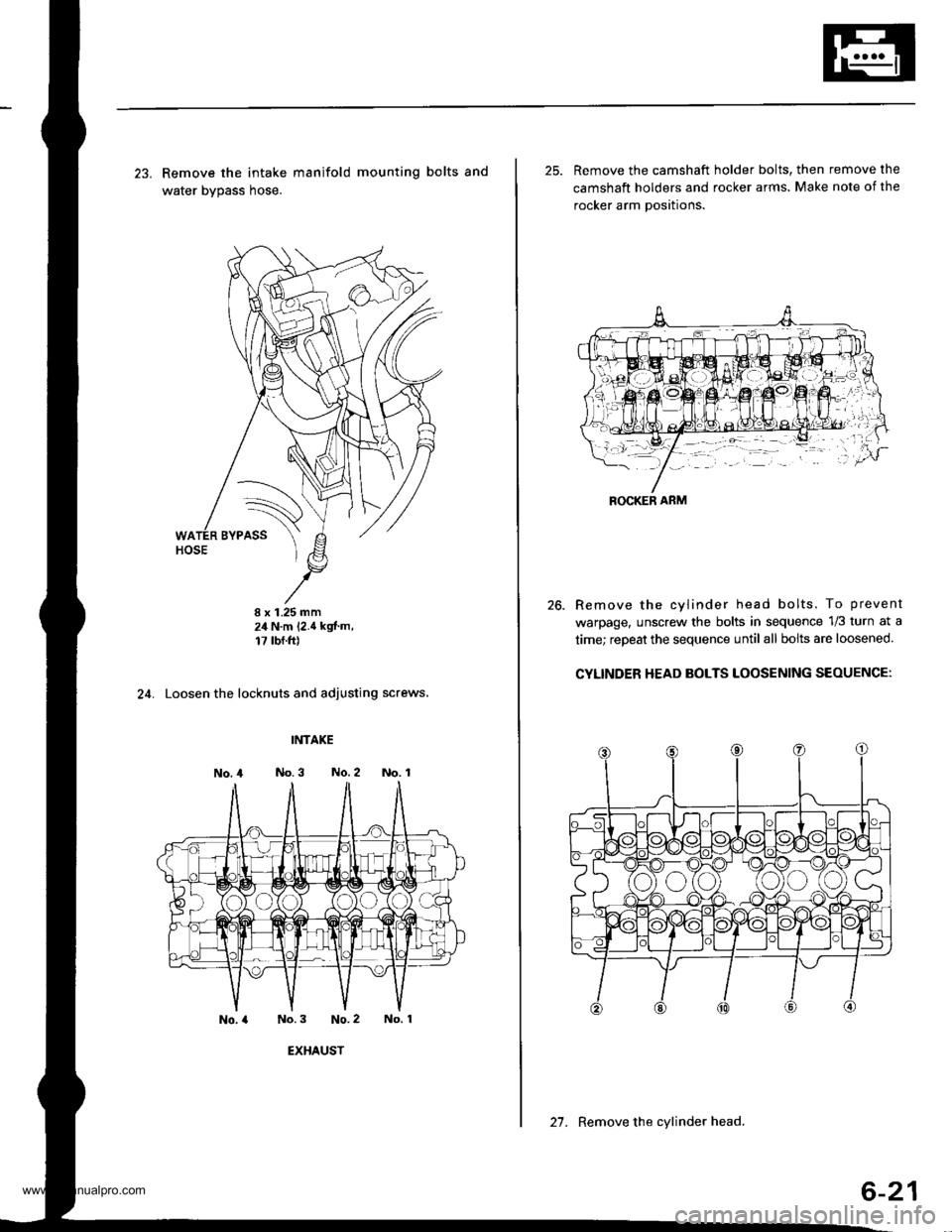
23. Remove the intake manifold mounting bolts and
water bvDass hose.
8 x 1.25 mm2,1 N.m 12.4 kgt.m,17 tbf.ft)
24. Loosen the locknuts and adjusting screws,
INTAKE
No.3 No.2 No. 1
No.3 No.2 No. 1
EXHAUST
No. 4
27. Remove the cylinder head.
6-21
25. Remove the camshaft holder bolts, then remove the
camshaft holders and rocker arms. Make note of the
rocker arm Dositions.
26. Remove the cylinder head bolts. To prevent
warpage, unscrew the bolts in sequence 1/3 turn at a
time; repeat the sequence until all bolts are loosened.
CYLINDER HEAD BOLTS LOOSENING SEOUENCE:
ROCKER ARM
www.emanualpro.com
Page 140 of 1395
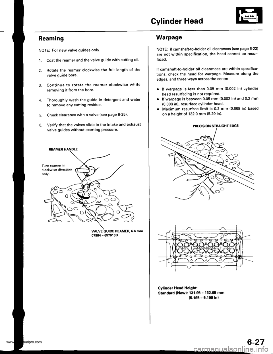
Cylinder Head
Reaming
NOTE: For new valve guides only.
1. Coat the reamer and the valve guide with cutting oil.
2. Rotate the reamer clockwise the full length of the
valve guide bore.
Continue to rotate the reamer clockwise while
removing it from the bore.
Thoroughly wash the guide in detergent and water
to remove anY cutting residue.
Check clearance with a valve (see page 6-25).
Verify that the valves slide in the intake and exhaust
valve guides without exerting pressure.
3.
4.
5.
6.
vALvE GUIDE REAMER,6.6 mm0798i1 - 657010O
REAMER HANDLE
e
Warpage
NOTE: lf camshaft-to-holder oil clearances (see page G22)
are not within specification, the head cannot be resur-
faced.
lf camshaft-to-holder oil clearances are within specifica-
tions, check the head for warpage. Measure along the
edges, and three ways across the center.
. if warpage is less than 0.05 mm (0.002 in) cylinder
head resurfacing is not required
lf warpage is between 0.05 mm (0.002 in) and 0.2 mm
(0.008 in), resurface cylinder head.
Maximum resurface limit is 0.2 mm (0.008 in) based
on a height of 132.0 mm (5.20 in).
Cylind€r Hesd Height:
Standard {New}: 131.95 - 132.05 mm
15.195 - 5.199 inl
PRECISION STRAIGHT EDGE
6-27
www.emanualpro.com
Page 189 of 1395
Cooling
f ffustrated Index ........... ..... 1O-2
Radiator
Rep|acement ...........,....,...................... 10-4
Engine Coolant Refilling and
Bleeding ..,.,................. 10-5
Cap Testing .................... 10-7
Testing ......10-7
Thermostat
Rep|acement ....................................... 10-8
Testing ...... 10-9
Water Pump
lllustrated lndex ....,..... .. 10-10
Inspection . 10-1 1
Replacement ....................................,.. 10-1 1
Fan Gontrol
Component Location Index ............... 10-12
Circuit Diagram ............. 10-13
Fan Motor Testing ......... 10-14
Radiator Fan Switch Testing ............. 10-14
Coolant Temperature Gauge
Gauge Testing ............... 10-15
Coolant temperature Sending
Unit Testing ........,....... 10-15
www.emanualpro.com