1997 HONDA CR-V cylinder head
[x] Cancel search: cylinder headPage 27 of 1395
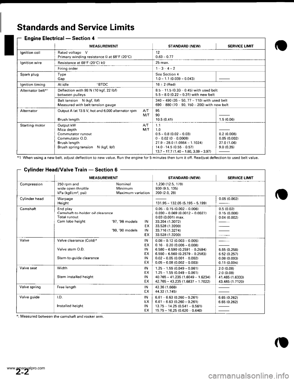
MEASUREMENTSTANDAFD INEWISERVICE LIMIT
lgnition coilRated voltage VPrimary winding resistance 0 at 68'F (20'C)120.63 0.77
lgnition wireBesistance at 68"F (20 C) ktl25 max.
Firing order1 3 4-2
Spark plugTypeGapSee Section 41.0 - 1.1 (0.039 - 0.043)
lgnition timingAt idle BTDC161 2 {Red)
Alternator belt*rDeflection with 98 N {10 kgf, 22 lbf)8.5 11.510.33 0.45)with used belt5.5 - 8.0 (0.22 - 0.31) with new belt
Belt tension N {kgf, lbt)Measured with bek tension gauge340 - 490 {35 - 50, 77 110) with used belt690 880 (70 90, 150 - 200i with new belt
AlternatorOutput A (at 13.5 V, hot and 6,000 alternator rpm AIIM/IBrush length
959010.5 (0.41)1.5 (0.06i
Staning motorOutput kW A/fMica depth MfiCommutator runoutCommutator O.D.Brush lengthBrush spring tension N (kgf, lbf)
1.11.00.5 - 0.8 {0.02 - 0.03)0,0.02 (0 0.0008)27.9 28.0 (1.0984 1.1024)14.0 14.5 (0.55 0.57)13.7 - 17.7 (1.40 - 1.80,3.09 - 3.97)
0.2 (0.008)
0.0s (0.002)
27.0 (1.06)
9.0 (0.35)
Standards and Service Limits
Engine Electrical - Section 4
'1 When using a new belt, ddiust deflection to new value. Run the engine for 5 minutes then turn it of{. Beadiust deflection to used belt value.
Cylinder Head/Valve Train - Section 6
MEASUREMENTSTANDARD {NEW} SERVICE LIMIT
Compression250 rpm and Nominalwide open throttle MinimumkPa (kgflcm'�, psi) Maximum variation
1 ,230 i'12 .5 , 11Al930 (9.s, 135)200 12.0,2al
Cylinder headWarpageHeight131.95 - 132.05 {5.195 - 5.199)0.05 {0.002)
CamshaftEnd playCamshaft to hoider oil clearanceTotal runoutCam lobe height '97,'98 models lNEX'99,'00 models lNEX
0.05 0.1s (0.002 0.006)0.030 - 0.069 (0.0012 - 0.0027)0.03 {0.001)max.33.204 \1.3072133.528 {1.3200)33.1 16 \1 .321 4)33.528 {'1.3200)
0.5 (0.02)
0.15 (0.006)
0.04 (0.002)
Valve clearance (Cold)* lNEXValve stem O.D. lNEXStem'to-guide clearance lNEX
0.08 - 0.12 (0.003 0.005)0.16 0.20 (0.006 - 0.008)6.580 - 6.590 (0.2591 0.2594)6.550 - 6.560 (0.2579 0.2s83)0.02 - 0.05 {0.00t 0.002)0.05 - 0.08 (0.002 0.003)
u* to.rutt6.52lO.257l0.08 {0.003i0.'1t (0.004)
width tNEXStem installed height lNEX
1.25 - 1.55 (0.049 - 0.061)1.25 1.55 (0.049 - 0.061)40.765 - 41.235 {1.6049 1.6234)42.765 - 43.235i'1.6837 - 1.70221
2.0 (0.08)
2.0 (0.08)
41.485 {1.6333}43.485 {1.7120i
Valve springFree length lNEX42.36 (1.668i
44.32 t1 .1 451
Valve guideI,D, INEXInstalled height tNEX
6.61 6.63 10.260 - 0.261)6.61 6.63 {0.260 - 0.261i13.75 - 14.25 10.541 0.561i15.75 - 16.25 {0.620 0.640i
6.6510.26216.65 (0.262i
*: Measured between the camshaft and rocker arm,
2-2
www.emanualpro.com
Page 38 of 1395

--
-
METRICITEMENGLISHNOTES
AIR CONDITIONINGCooling capacity3,520 Kcal/h j 14,000 BTU/h
Compressor Type/manutacturerNo. of cylinderCaPacityMax. speedLubricant capacityLubricant type
Scroll/KElHlN
85.7 mf/rev | 5.23 cu'in/rev10,000 rpm130mf 1 algIlozsP-10
Condenser TypeCorrugated fin
Evaporator TypeCorrugated fin
Blower TypeMotor inputSpeed controlMax. capacity
Sirocco fan200 w 112 v4-Speeo440 m3/h 15,500 cu fvh
Temperature control
Compressor clutch TypePower consumptionDry, single plate, poly-V-belt drive40 W max./12 VAt 68'F (20 C)
Befrigerant TypeOuantity
HFC-134a 1R-134a)zoo o' g 24j an oz
STEERING SYSTEMTypeOverall ratioTurns, lock to lockSteering wheel diameter
Power assisted, rack and pinion
SUSPENSIONType Front
Bear
Shock absorber Front and Rear
Independent double wishbone, coil springwith stabilizerIndependent double wishbone, coil springwith stabilizerTelescopic, hydraulic nitrogen gas tilled
WHEEL ALIGNMENTCamber
CasterTotaltoe
FronthearFrontFrontRear0inln 1/16 in0mmln2mm
0'- r"00'2.10'�
BRAKE SYSTEMTvpe
Pad surface areaLining surface areaParking brake
Front
RearFrontRearTvpe
Power-assisted selt-ad,ustingventilated discPower assisted self-adiusting drum49 cm, x 2 7.6 sq-in x 273 cm, x2 11.3 sq-in x 2Mechanical actuating, rear two wheel brakes
Drum brake
TIRESize and pressureSee tire inlormation label.
ELECTRICALBafteryStarterAlternator
In under-dash fuse/relay boxIn under hood fuse/relay box
In underhood ABS fuse/relay boxHeadlightsFront turn signal lights
Front parking lightsFront side marker lightsRear side marker lightsRear turn signal lightsErake/parking lightsBack-up lightsCeiling lights {fronvrear)License plate lightSpotlightsHigh mount brake lightlgnition key lightAshtray lightGauge lightsIndicator lightslllLrmination and pilot IightsHeater illumination lights
12 V, 36 AH/s HR12V 1.0, 1.1 kW12V 100A
7.5 A, 10 A, 15 A, 20 A7.5 A, 10 A, 15 A, 20 A, 30 A, 40 A'100 A7.5 4,20 A. 40 A12V 60/55 W12 V- 21 W ('97 model),12 V - 27 W ('98-00 models)12V 5 W {'97 model),3 CP ('98 - 00 models)12V-8W12 V,3 CP12V-21W12 V 2115 W12V 21 CP (18 W)12V-8W12V-8W12V-5W12V -21W
12 V- 1.4 W12V 1.4 W12 V 1.4 W,3 W,3.4 W12V-0.84W, 1.12 W, 1.4 W,3 W, LED12 V - 0.84 W, 1.4 W, LED12 V,1.4 W
2-13
www.emanualpro.com
Page 67 of 1395
e
o
I'
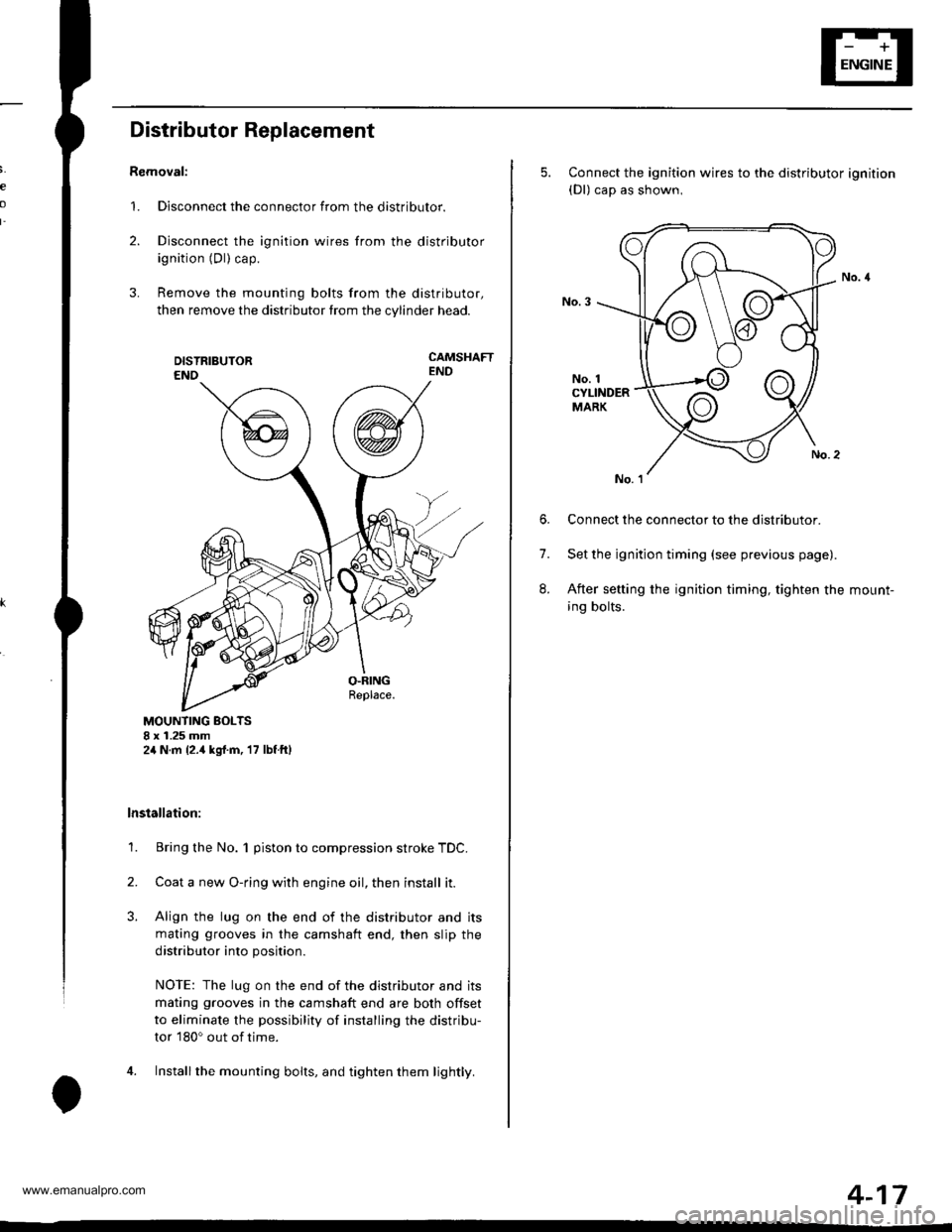
Distributor Replacement
Removal:
1. Disconnect the connector from the distributor.
2. Disconnect the ignition wires from the distributor
ignition (Dl) cap.
3. Remove the mounting bolts from the distributor,
then remove the distributor from the cylinder head.
CAMSHAFTEND
MOUNTING BOLTS8 x 1.25 mm2,1N.m {2.,1kgrf.m, 17 lbf ftl
lnstallation:
1. Bring the No. 1 piston to compression stroke TDC.
2. Coata new O-ring with engine oil, then install it.
3. Align the lug on the end of the distributor and its
mating grooves in the camshaft end, then slip the
distributor into position.
NOTE: The lug on the end of the distributor and its
mating grooves in the camshaft end are both offset
to eliminate the possibility of installing the distribu-
tor 180o out of time.
4. Installthe mounting bolts, and tighten them lightly.
5. Connect the ignition wires to the distributor ignition(Dl) cap as shown,
No. 1CYLINDERMARK
6. Connect the connector to the distributor.
7. Set the ignition timing (see previous page).
8. After setting the ignition timing, tighten the mount-
ing bolts.
4-17
www.emanualpro.com
Page 96 of 1395

Engine
Engine RemovaUlnstallation ................ 5-1
Cylinder Head/Valve Train ................... 6-1
Engine Bfock .......... ...........7-1
Engine Lubrication ...........8-1
Intake Manifold/Exhaust System ........ 9-1
Cooling ......... 10-1
www.emanualpro.com
Page 114 of 1395
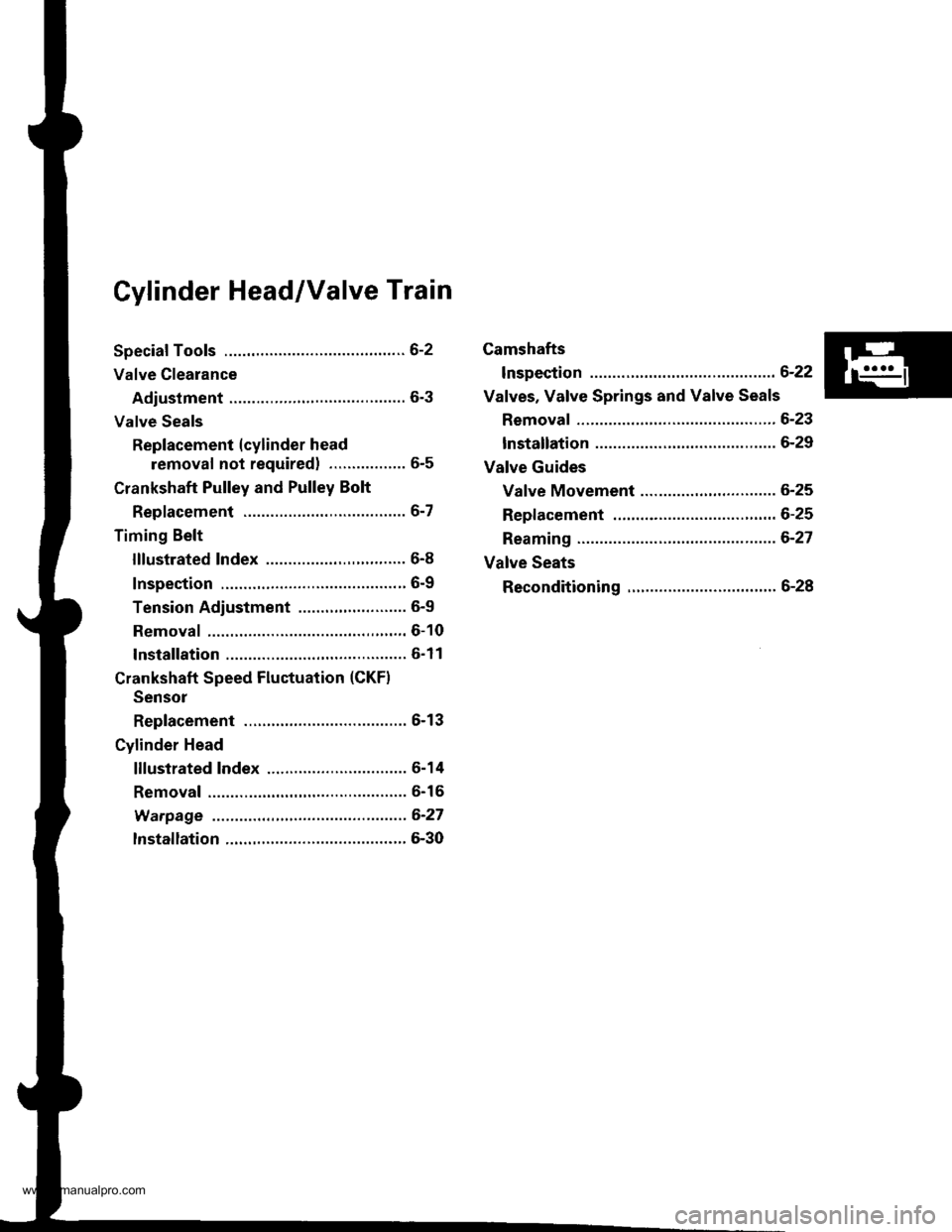
Cylinder Head/Valve Train
Speciaf Tools .............6-2
Valve Clearance
Adiustment ............6-3
Valve Seals
Replacement (cylinder head
removal not requiredl ................. 6-5
Crankshaft Pulley and Pulley Bolt
Replacement .........6-7
Timing Belt
I llustrated lndex ............................... 6-8
Inspection ............., 6-9
Tension Adjustment ........................ 6-9
Removal ...........,..... 6-10
lnstallation .............6-11
Crankshaft Speed Fluctuation (CKFI
Sensor
Replacement .........6-13
Cylinder Head
lllustrated lndex ............................... 6-14
Removal .................6-16
Warpage ................6-27
lnstallation ............. 6-30
Camshafts
lnspection ..............6-22
Valves, Valve Springs and Valve Seals
Removal ................, 6-23
lnstallation ............. 6-29
Valve Guides
Valve Movement ............,,,,.,............ 6-25
Replacement .........6-25
Reaming .................6-27
Valve Seats
Reconditioning ......6-28
www.emanualpro.com
Page 116 of 1395

Valve Clearance
Adiustment
Adjust the valves only when the cylinder head tempera-
ture is less than 100"F (38"C).
1. Remove the cylinder head cover.
Remove the middle cover (see page 6-11).
Set the No. 1 piston at TDC. The "UP" mark on the
pulleys should be at the top, and the TDC marks on
the pulleys should align with the pointers on the back
POINTERPOINTER
Adjust the valves on No. 1 cylinder.
Intake: 0.08 - 0.12 mm (0.003 - 0.005 inl
Exhaust: 0.16 - 0.20 mm (0.006 - 0.008 in)
Loosen the locknut, and turn the adiustment screw
until the feeler gauge slides back and forth with a
slight amount of drag.
LOCI(NUT9 x 0.75 m.n
Adiusting Screw Locations:
INTAKE
No.4 No.3 No.2
(cont'd)
6-3
25 N.m 12.5 kgf.m, 18lbf.ft)
EXHAUST
No. 1
www.emanualpro.com
Page 117 of 1395
Valve Clearancev
Adjustment (cont'dl
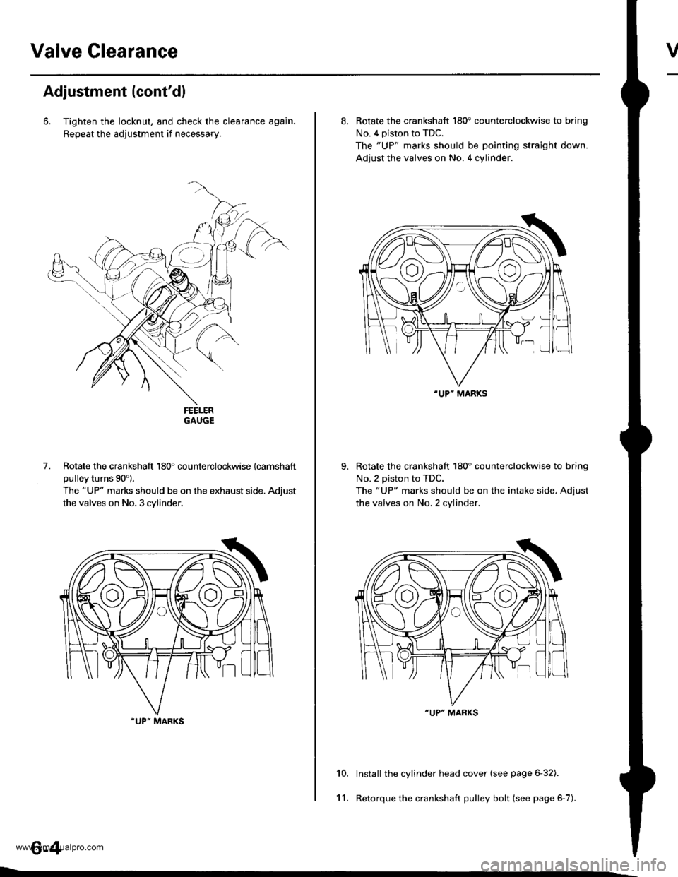
6. Tighten the locknut, and check the clearance agajn.
Repeat the adjustment if necessary.
GAUGE
Rotate the crankshaft 180" counterclockwise (camshaft
pulley turns 90').
The "UP" marks should be on the exhaust side. Adjust
the valves on No. 3 cylinder.
.UP" MARKS
7.
8. Rotate the crankshaft 180" counterclockwise to brinq
No. 4 piston to TDC.
The "UP" marks should be pointing straight down.
Adjust the valves on No. 4 cylinder.
Rotate the crankshaft 180'counterclockwise to brino
No.2 piston to TDC.
The "UP" marks should be on the intake side. Adiust
the valves on No. 2 cylinder.
Install the cylinder head cover (see page 6-32).
Retorque the crankshaft pulley bolt (see page 6-7).
10.
11.
"UP" MARKS
"UP" MARKS
www.emanualpro.com
Page 118 of 1395
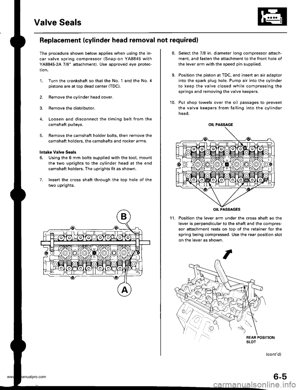
Valve Seals
Replacement (cylinder head removal not required)
The procedure shown below applies when using the in-
car valve spring compressor (Snap-on YA8845 with
YA8845-2A 7/8" auachment). Use approved eye protec-
tion.
1. Turn the crankshaft so that the No. 1 and the No. 4
pistons are at top dead center (TDC).
2. Remove the cylinder head cover.
3. Remove the distributor.
4. Loosen and disconnect the timing belt from the
camshaft pulleys.
5. Remove the camshaft holder bolts. then remove the
camshaft holders, the camshafts and rocker arms.
lntake Valve Seals
6. Using the 6 mm bolts supplied with the tool, mount
the two uprights to the cylinder head at the end
camshaft holders. The uprights fit as shown.
7. Insert the cross shaft through the top hole of the
two uprights,
at.
9.
Select the 7/8 in. diameter long compressor attach-
ment, and fasten the attachment to the front hole of
the lever arm with the speed pin supplied.
Position the piston at TDC, and insen an air adaptor
into the spark plug hole. Pump air into the cylinder
to keep the valve closed while compressing the
springs and removing the valve keepers.
10. Put shop towels over the oil passages to prevent
the valve keepers from falling into the cylinder
head.
Position the lever arm under the cross shaft so the
lever is perpendicular to the shaft and the compres-
sor attachment rests on top of the retainer for the
spring being compressed. Use the rear position slot
on the lever as shown,
't1.
OIL PASSAGE
OIL PASSAGES
(cont'd)
6-5
www.emanualpro.com