Page 262 of 1395
Troubleshooting
Troubleshooting Procedures
How To Begin Troubleshooting
When the Malfunction indicator Lamp (MlLl has been reported on, or there is a driveability problem, use the appropri-ate procedure below to diagnose and repair the problem.
A. When the MIL has come on:
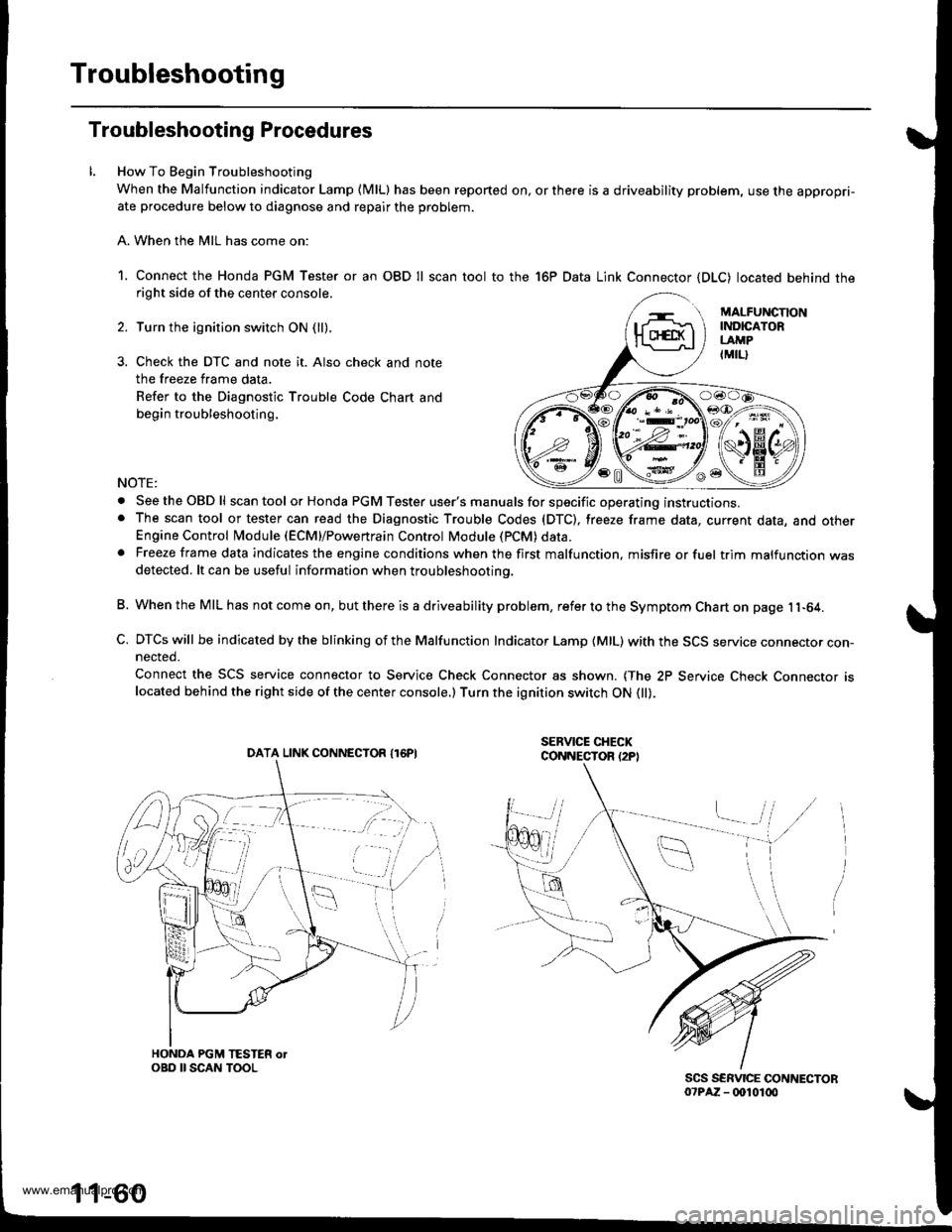
1. Connect the Honda PGM Tester or an OBD Il scan tool to the 16P Data Link Connector (DLC) located behind theright side of the center console.
Turn the ignition switch ON (ll).
Check the DTC and note it. Also check and note
the freeze frame data.
Refer to the Diagnostic Trouble Code Chart and
begin troubleshooting.
NOTE:
. SeetheOBDll scan tool or Honda PGM Tester user's manuals for specific operating instructions.. The scan tool or tester can read the Diagnostic Trouble Codes (DTC), freeze frame data, current data, and otherEngine Control Module (ECM}/Powertrain Control Module (PCM) data.. Freeze frame data indicates the engine conditions when the first malfunction, misfire or fuel trim malfunction wasdetected. lt can be useful information when troubleshootino.
B. When the MIL has not come on, but there is a driveability problem, refer to the Symptom Chart on page 11-64.
C. DTCs will be indicated by the blinking of the Malfunction Indicator Lamp {MlL) with the SCS service connector con-nected.
Connect the SCS service connector to Service Check Connector as shown. {The 2P Service Check Connecror rslocated behind the right side of the center console.) Turn the ignition switch ON 0l).
DATA LINK CONNECTOR I16PI
1 1-60
www.emanualpro.com
Page 294 of 1395
![HONDA CR-V 1997 RD1-RD3 / 1.G Workshop Manual
PGM-FI System
Manifold Absolute Pressure (MAP) Sensor (contd)
[tn,t nn-] The scan tool indicates Diagnostic Trouble Code (DTC) P0108: A high voltage (low vacuum) problem in the|jg Manifold Absolute HONDA CR-V 1997 RD1-RD3 / 1.G Workshop Manual
PGM-FI System
Manifold Absolute Pressure (MAP) Sensor (contd)
[tn,t nn-] The scan tool indicates Diagnostic Trouble Code (DTC) P0108: A high voltage (low vacuum) problem in the|jg Manifold Absolute](/manual-img/13/5778/w960_5778-293.png)
PGM-FI System
Manifold Absolute Pressure (MAP) Sensor (cont'd)
[tn,t nn-] The scan tool indicates Diagnostic Trouble Code (DTC) P0108: A high voltage (low vacuum) problem in the|jg Manifold Absolute Pressure (MAP) sensor.
MAP SENSOR 3P CONNECTOR IC131I
Wire side of female terminals
vcclIYEL/RED}
PCM CONNECTOR D I16PI
JUMPER WIRE
sGlIGRN/WHTI
Wire side of lemale termin6ls
1
(To page 11,93)': '98 - 00 models
1-92
tcRN/wHrll IIRED/GRN|
The MIL has boen reported on.DTC m108 is slored.
Problem veritication:1. Start the engine. Hold theengine at 3,000 rpm with noload (in Park or neutral) untilthe radiator fan comes on, thenlet it idle.2. Check the MAP with the scantool.
Intermittent tailuro, system i3 OKat this time. Check tor ooor con-nections or loose wires at C131IMAP s6nsor) snd the ECM/rcM.
ls 101 kPa {760 mmHg,30 in.Hg),2.9 V or higher indicated?
Check Ior an open in the MAPsensor:1. Turn the ignition switch OFF.2. Disconnect the MAP sensor3P connector.3. lnstall a jumper wire betweenthe MAP sensor 3P connectorterminals No.3 and No.2.4. Turn the ignition switch ON {ll).5. Check the MAP with the scantool.
ls 10'l kPa (760 mmHg,30 in.Hg),2.9 V or higher indicated?
Check for an open in wire (SGlliDel:1. Remove the jumper wire.2. Measure voltage between theMAP sensor 3P connector ter-minals No. 1 and No- 2.
R6p.ir open in the wire betwoenthe ECM/PCM (D12, CTrl and theMAP sensor.
ls there approx. 5 V?
Check for an open in the wire(MAP line):1. Turn the ignition switch OFF.2. lnstall a iumper wire on thePCM connectors between D3and D12.3. Turn the ignition switch ON (ll).4. Check the MAP wirh the scantool.
Ropair opon in the wire betweenthe PCM {D3, .nd the MAP son-3('t.
ls 101 kPa 1760 mmHg, 30 in.Hg),2.9 V or higher indicated?
YES
www.emanualpro.com
Page 296 of 1395
PGM-FI System
Manifold Absolute Pressure (MAP) Sensor (cont'dl
The scan tool indicates Diagnostic Trouble Code (DTC) P1128: Manifold Absolute pressure (MAp) lower thanexoected.
The scan tool indicates Diagnostic Trouble Code (DTC) P'l129: Manifold Absolute Pressure (MAP) higher thanexpected.
l
- The MIL has be6n r€ported on.- DTC Pl128 is stored.
Problom verification:1. Turn the ignition switch ON 1lli.2. Check the MAP with the scantool,
ls 54.1 kPa (406 mmHg, 16.0 in.Hg),1.61 V or higher indicated?I to.mittent failure, 3ydom i! OKal thbtimc,
- The MIL has boen reportod on.- DTC Pl129 is stored.
Problem veritication:1. Start the engine. Hold theengine at 3,000 rpm with noload lin Park or neutral) untilthe radiator fan comes on,then Iet it idle.2. Check the MAP with the scantool,
ls 43.3 kPa (325 mmHg, 12.8 in.Hg),'1.32 V or less indicated?Intarmittani fuilure, systom i3 OKat this time.
11-94
www.emanualpro.com
Page 297 of 1395
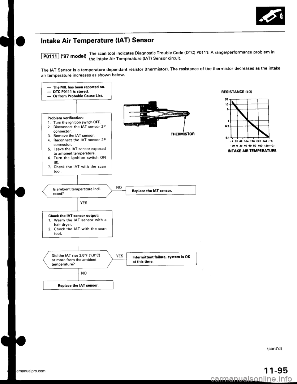
The IAT Sensor is a temperature dependant resistor (thermistor). The resistance of the thermistor decreases as the intake
air temDerature increases as shown below
RESISTANCE IKOI
Intake Air Temperature (lAT) Sensor
1P0111 | ('97 model)The scan tool indicates Diagnostic Trouble code (DTC) P0111: A ranoe/performance problem in
the lntake Air TemDerature (lAT) Sensor circuit.
. 3' aa ro. r?a arl ,.t r.fl20 0 to ao ao aa ioo t2otocl
INTAKE AIB TEMPERATURE
- The MIL has been reported on.- DTC P0111 is stored.- Or lrom Probable Cause List.
Problem vetification:1. Turn the ignition switch OFF.
2. Disconnect the IAT sensor 2P
connector,3. Remove the IAT sensor.4. Reconnect the IAT sensor 2P
connector,5. Leave the IAT sensor etposedto ambient temPerature.6. Turn the ignition switch ON
flr).7. check the IAT with the scan
tool-
R€place the IAT son3or.
Check the IAT sensor output:1. Warm the IAT sensor with ahair dryer.2. Check the IAT with the scan
tool.
Did the IAT rise 2.0'F (1.0'C)
or more from the ambienttemperature?
Intermittent f.ilure, aY3tem is OKai this tim6.
Replace the IAT sensor.
(cont'd)
1 1-95
www.emanualpro.com
Page 299 of 1395
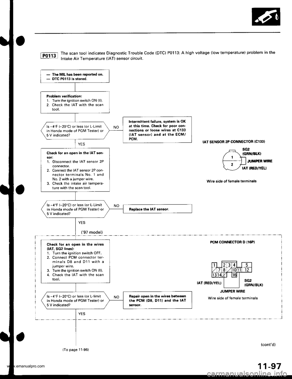
The scan tool indicates Diagnostic Trouble Code (DTC) P0113: A high voltage (low temperature) problem in the
Intake Air Temperature (lAT) sensor circuit.
IAT SENSOR 2P CONNECTOR ICl33I
sG2{GRN/BIIO
JUMPEN WNE
IAT IRED/YELI
Wire side ol female terminals
YES
_!!7rqd9ll_____-
FCM CONNECTOR O IT6PI
IAT IRED/YEL)sG2IGRN/BLK}
JUMPER w|BE
Wire side of female terminals
l
(cont'd)
11-97
The MIL has been reported on.OTC P0113 is stored.
Problem v€rification:1. Turn the ignition switch ON (ll).
2. Check the IAT with the scantool,
Intermiftent failure, syatem is OKat this time. Ch.ck for Door con-nections or loose wires at c133
llAT s6nsorl and at the ECM/PCM.
ls -4'F (-20"C) or less (or L Limitin Honda mode of PGM Tester)or5 V indicated?
Check lor an open in the IAT sen-sor:1. Disconnect the IAT sensor 2Pconnector,2. Connect the IAT sensor 2P connector terminals No. 1 andNo. 2 with a ,umper wire.3. Check the intake air tempera'ture with the scan tool.
ls -4'F (-20"C) or less (or L-Limitin Honda mode oI PGM Tester)or5 V indicated?Replace the IAT sensor.
Check lor en opan in the wires
llAT, SG2 lines):1. Turn the ignition switch OFF.2. Connect PCM connector ter-minals D8 and D11 with a
3. Turn the ignition switch ON lll).4. Check the IAT with the scantool.
Rgpair open in the wires b€tweenthe PcM (D8. D11) and rhe IAT3en30r,
ls -4"F {-20"C) or Iess (or Llimitin Honda mode ot PGM Tester)or5 V indicated?
(To page 11-98)
www.emanualpro.com
Page 301 of 1395
Engine Goolant Temperature (ECTI Sensor
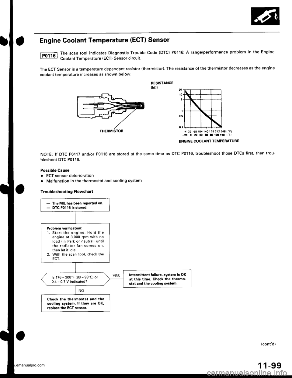
The scan tool indicates Diagnostic Trouble Code (DTC) P0116: A range/performance problem in the Engine
Coolant Temperature (ECT) Sensor circuit.
The ECT Sensor is a temperature dependant resistor (thermistor). The resistance of the thermistor decreases as the engine
coolant temperature increases as shown below
RESISTANCEtk0l
NOTE: lf DTC P0117 and/or P0118 are stored at the same
bleshoot DTC P0116.
Possible Cause
a ECT sensor deterioration
. Malfunction in the thermostat and cooling system
Troubleshooting Flowchart
-4 32 68 r0a r a0176 212 2aE {'r)-2O O 20 ito tO .o ! t2O I c)
ENGINE COOLANT TEMPERATURE
time as DTC P0116, troubleshoot those DTCS first, then trou-
THERMISTON
- The MIL has be€n roported on.- DTC P01'16 is stored.
Probl6m verification:1. Start the engine. Hold theengine at 3,000 rpm with noload (in Park or neutral) untilthe radiator fan comes on,then let it idle.2. With the scan tool, check theECT.
Intermittent failure, sYstem b OKat this tim6. Check lhe thermo-stat and the cooling 5y3tom.
ls 176 - 200'F (80 - 93"C) or0.4-0.TVindicated?
Check the thermostat and the
cooling system. It th€y are OK,reolace the ECT seNor.
(cont'd)
1 1-99
www.emanualpro.com
Page 303 of 1395
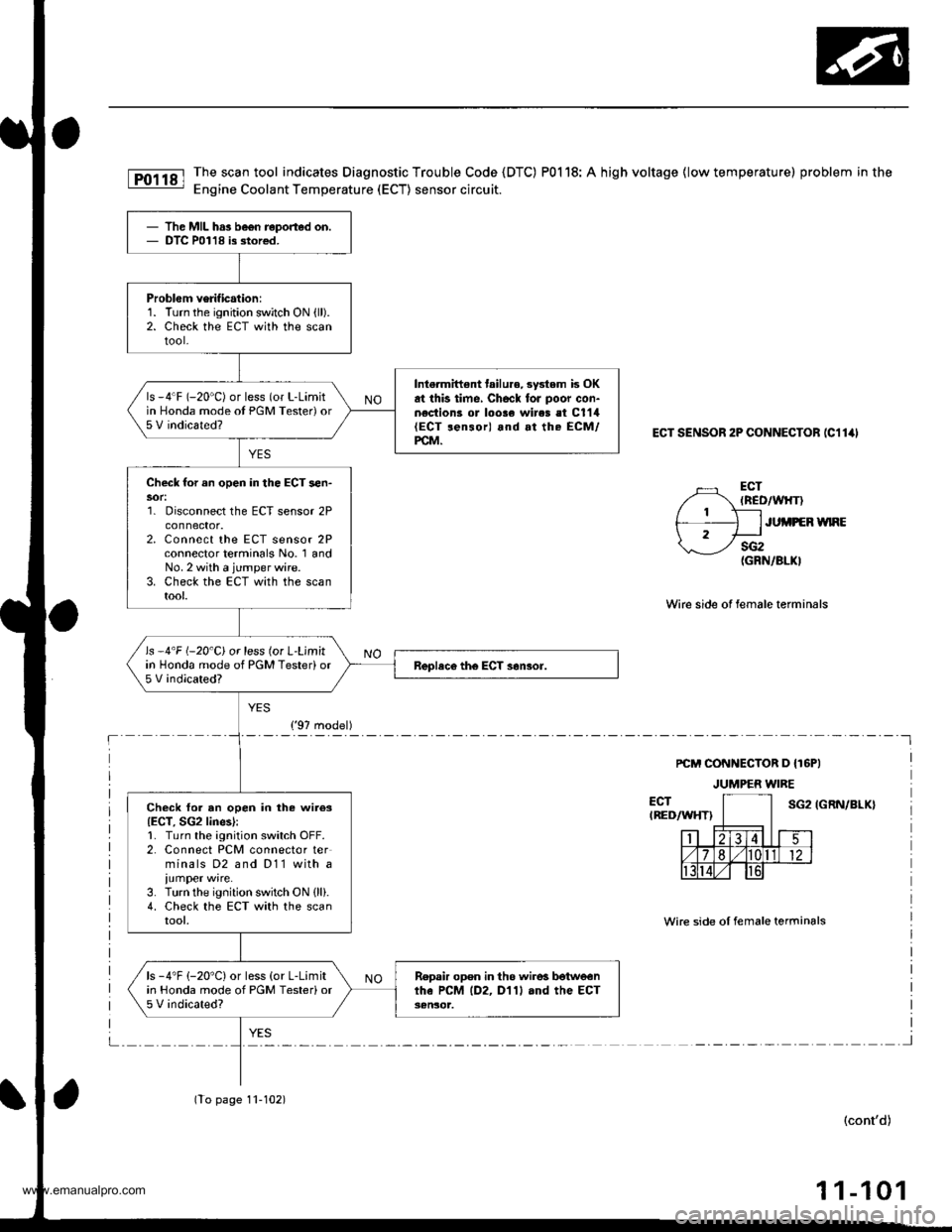
The scan tool indicates Diagnostic Trouble Code {DTC) P0118: A high voltage {low temperature) problem in the
Engine Coolant Temperature (ECT) sensor circuit.
ECT SENSOR 2P CONNECTOB (C11ill
ECT(ncD/wlrT)
ECTIREDAAIHT)
Wirc side of lemale terminals
sG2(GRN/8LKI
PCM CONNECTOR D {T6PI
JUMPER WIRE
JUi,IPEB WNE
IGRN/BLX}
Wire side oI female terminals
(cont'd)
1 1-101
The MIL has be€n reported on.DTC P01'18 is stor€d.
Problem verification:1. Turn the ignition switch ON {ll).2. Check the EcT with the scantool-
Intermiftent tailu.€,3ystem is OKat this time, Checl foJ poor con-n€ction3 or loose wires et C1'14(ECT ren3or) and at the ECM/PCM.
ls -4"F (-20'C) or less (or L-Limitin Honda mode ot PGM Tester) or5 V indicated?
Check for an open in the ECT sen-
1. Disconnect the ECT sensor 2Pconnector.2. Connect the ECT sensor 2Pconnector terminals No. 1 andNo. 2 with a jumper wire.3. Check the ECT with the scantool.
ls -4'F (-20'C) or less (or L'Limitin Honda mode of PGM Tester)or5 V indicated?
Check for an open in the wiies{ECT, SG2 lines):1. Turn the ignition switch OFF.2. Connect PCM connector terminals D2 and D11 with a
iumper wire.3. Turn the ignition switch ON {ll}.4. Check the ECT with the scantool,
ls -4"F (-20'C) or less (or L-Limitin Honda mode of PGM Testerior5 V indicated?
Repair open in th6 wire! botwe€nthe PCM lD2, D'l1l and the ECT3€n30t.
('97 model)
(To page 11-102)
www.emanualpro.com
Page 311 of 1395
- The MIL has been reported on.- DTC Pl121 is stored,
Problem veritication:1. Turn the ignition switch ON (ll).
2. Check the throttle position
with the scan tool.
ls 14.1% (12.97.)* or higherindicated when the throttle isfully opened?
Intormittent failur6, systom is OKat this lime.
- The MIL has b€en reoorted on.- OTC P1122 is dored.
Problem verification:1. Turn the ignition switch ON lll).2. Check the throttle positionwith the scan tool.
ls'17.670 (16.9%)' or lessindicated when the throftle islully closed?
IntermitteDt tailu.o, system is OKat thb time.
Pl121 lThescantool indicates Diagnostic Trouble Code {DTC) Pl121;Throttle Position (TP) lowerthan expected.
I Pl122 | The scan tool indicates Diagnostic Trouble Code (DTC) P1122: Throttle Position (TP) higherthan expected.
*:'99 - 00 models
1-109
www.emanualpro.com