Page 487 of 2189

ldle Control System
{
(
a
Clutch Switch Signal (Dl6YS engine with M/Tl
This signals the ECM when the clutch is engaged.
A {32P}
ECM CONNECTORS
LGl (BRN/BLK)
\-
cLsw(RED}
Inrpaction ot dutch rwitch signal.
Check for on opon in the wiro(CLSW linel:'!. Turn the ignition switch ON (ll).2. Measure voltage betweon ECt!4connector terminals C29 andA9.
Ch.ck tho clutch switch:1. Turn the ignition switch OFF.2. Disconnect the 2P connectorfrom the clutch switch.3. Turn the ignition switch ON (ll).4. Measure voltage b€tween ECMconnector terminals C29 and
ls thare approx. 5 V?
ls there approx. 5 V?
Check for a short in th6 wire(CLSW line)l1. Turn the ignition swirch OFF.2. Disconnect the ECM connector C (31P)trom the ECM.3. Check lor continuity betweenECM connector terminal C29and body ground.
Chcck for an open in thg wire{CLSW linel:1. Depress the clutch pedal.2. Moasure voltage between ECMconnector torminals C29 andA9.
Repair short in the wirc betweentho ECM {C291 and tho clurchswitch.
Sub3titutg a known-good ECMand rechock, It p.e3cribed vohagoi! now available, roplace the orig-inal ECM.
Wire side of female terminals
26189101l12t3'tat5l617l822
o
(To page 11-219)
11-218
!
Page 491 of 2189
ldle Control System
ldle Speed Setting (cont'dl
Inspeqtion/Adiustment
38 D16Y5 engine whh M/T,'99 - 00 81642 engine
NOTE: Before setting the idle speed, check the follow-ing items;- The MIL has not been reported on.- lgnition timing- Spark plugs- Air cleaner- PCV system
'1. Start the engine. Hold the engine at 3,000 rpm withno load (transmission in neutral) until the radiatorfan comes on, then let it idle.
Connect a tachometer.
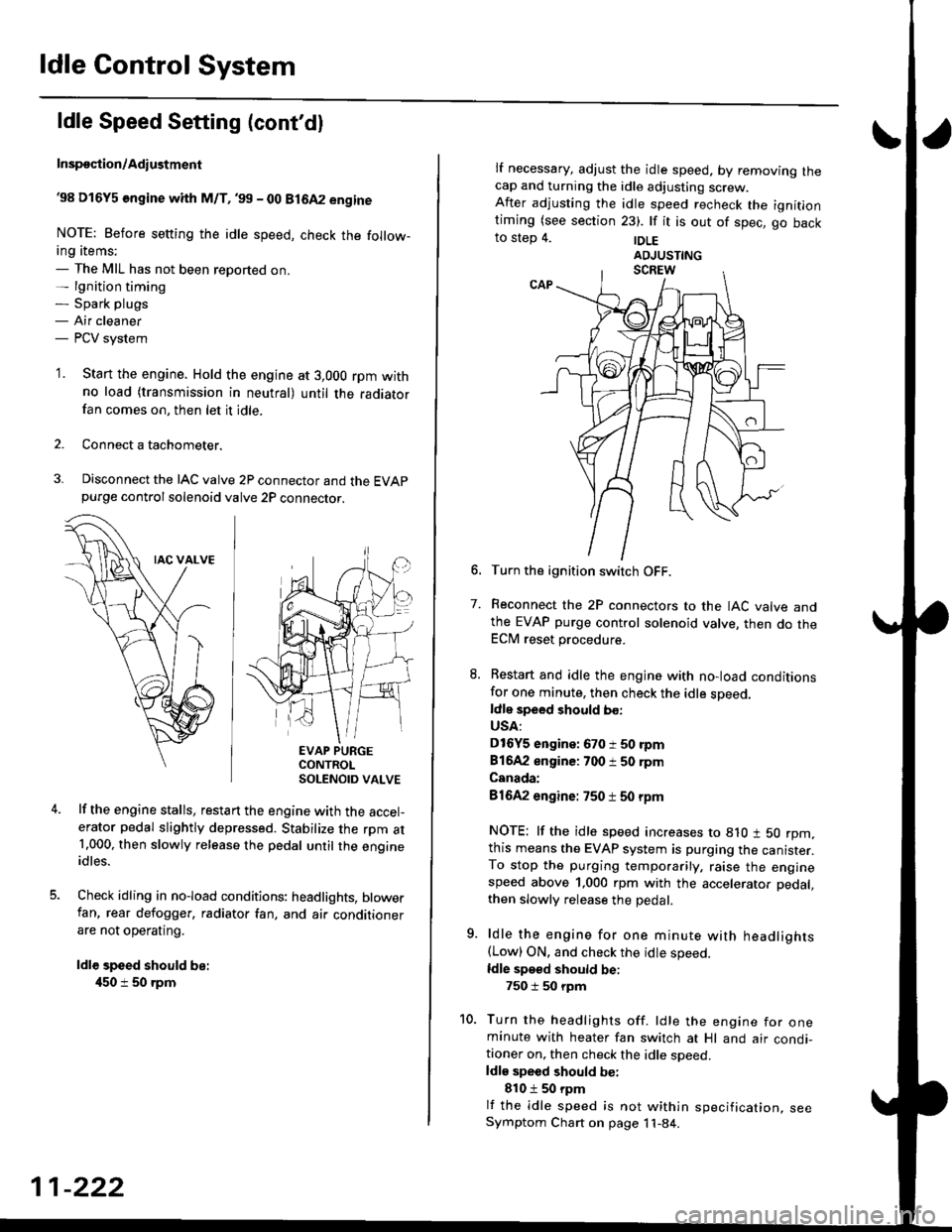
Disconnect the IAC valve 2P connector and the EVAPpurge controlsolenoid valve 2P connector.
EVAP PURGECONTROLSOLENOID VALVE
lf the engine stalls, restart the engine with the accel-erator pedal slightly depressed. Stabilize the rpm at1.000, then slowly release the pedal until the engineidles.
Check idling in no-load conditions: headlights, blowerfan, rear defogger, radiator fan, and air conditionerare not operating.
ldl€ speed should be:
450 i 50 rpm
11-222
lf necessary, adjust the idle speed, by removrng lnecap and turning the idle adjusting screw.After adjusting the idle speed recheck the ignitlontiming (see section 23). lf it is out of spec, go backto step 4. |DLE
6. Turn the ignition switch OFF.
7. Reconnect the 2P connectors to the IAC valve andthe EVAP purge control solenoid valve, then do theECM reset procedure.
8. Restart and idle the engine with no-load conditionsfor one minute, then check the idle sDeed.ldle speed should bo:
USA:
D16Y5 engine: 670 i 50 rpm
81642 engine: 700 i 50 rpm
Canada:
81642 engine: 750 t 50 rpm
NOTE: lf the idle speed increases to 8lO t 50 rpm,this means the EVAP system is purging the canister.To stop the purging temporarily, raise the enginespeed above 1,000 rpm with the accelerator pedal,
then slowly release the pedal.
9. ldle the engine for one minute with headlights(Low) ON. and check the idle speed.
ldle speed should be:
750 i 50 rpm
10. Turn the headlights off. ldle the engine for oneminute with heater fan switch at Hl and air condi-tioner on, then check the idle soeed.ldls speed should be:
810 t 50 rpm
lf the idle speed is not within specification, seeSymptom Chart on page 11-84.
Page 501 of 2189
Fuel Supply System
Fuel Injectors
Replacement
@ Do not smoke when working on the tuel systgm, Keep gp6n flames away from your work area
'f. Relieve the fuel pressure (see pages 11-230,231J.
2. Disconnect the connectors from thefuel injectors (D16Y7 engine: Remove the air cleaner).
3. Disconnect the vacuum hoses from thefuel pressure regulator. Placeashoptowel overthefuel return hose, then dis-connect it from the fuel pressure regulator. Disconnect the vacuum hoses and 2P connector from the EVAp purgecontrol solenoid valve.
4. Remove the retainer nuts on the fuel rail.
5. Disconnect the fuel rail.
6. Removethefuel injectors from the intake manifold.
D16Y5, D16Y8 engine:
NOTE: lllustration shows D16Y8 engine.
D16Y5 engine is similar.
12 N.m11.2 kgl.m,8.7 rbt.ft)
12 N.m11.2 lgl.m,8.7 rbt.ftl
.q
wE4
Y
Ve
ffi}Yg
E
O.RINGReplace.
CUSHIONRINGReplace.
O.RINGReplace.
cusl{toNRINGReplace.
SEALRINGReplace.
ffi
E
EV
R
w
t
YEVAPPURGE CONTNOLSOLENOID VALVE
FUEL
11-232
Page 502 of 2189
\J
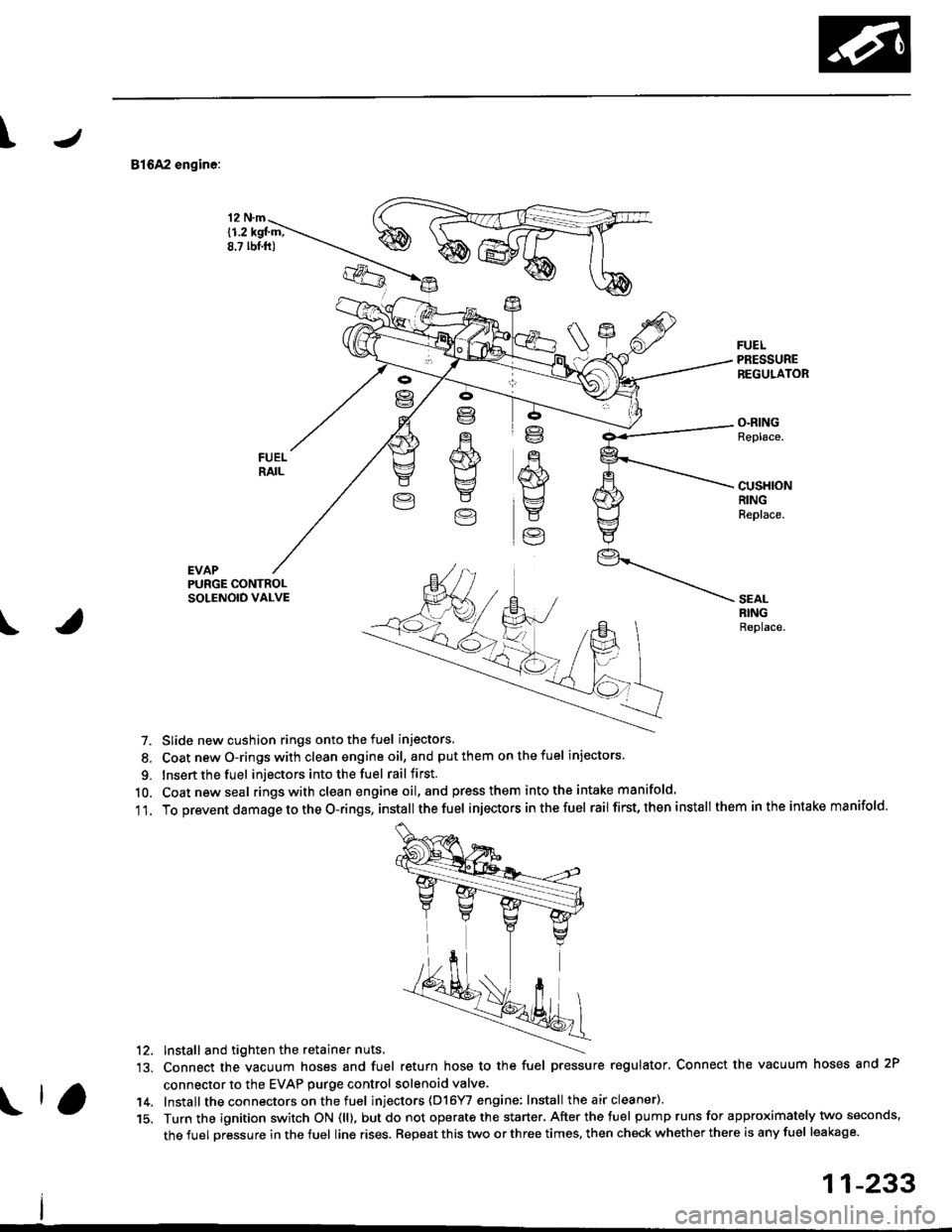
81642 engine:
EVAP
12 N.m
{1.2 kgl m;8.? lbt.ft)
FUELPRESSUREREGULATOR
O.RINGReplace.
cusHloNRINGReplace.
PURGE CONTROLSOLENOID VALVE
\
SEALRINGReplace.
7. Slide new cushion rings onto the fuel injectors.
8. Coat newO-ringswith clean engineoil, and putthem onthefuel injectors.
9. Insert the fuel injectors into the fuel rail first.
10. Coatnewseal rings with clean engine oil,and press them intothe intake manifold.
11. To prevent damage to the O-rings, installthe fuel injectors inthefuel rail first, then install them inthe intake manifold.
'12. Install and tighten the retainer nuts.
13. Connect the vacuum hoses and fuel return hose to the fuel pressure regulator, Connect the vacuum hoses and 2P
connector to the EVAP purge control solenoid valve.
14. Install the connectors on the fuel inl'ectors (D16YI engine; Install the air cleaner).
15. Turn the ignition switch ON (ll), butdo not operate the starter. After the tuel pump runs for approximately two seconds,
the fuel pressure in the fuel line rises. Repeat this two or three times, then check whether there is any fuel leakage.
11-233
Page 509 of 2189
Fuel Supply System
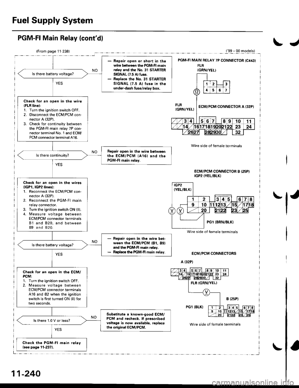
- Repair op€n or short in thewir€ betlveen the PGM-FI mainrelay and the No. 31 STARTERSIGNAL 17.5 A) fuse.- RoDlace the No. 31 STARTERSIGNAL {7,5 Al tuse in theunder-dash luse/rolay box.
ls there battery voltage?
Check tor an open in the wire(FLR linel:1. Turn the ignition switch OFF.2. Disconnect the ECM/PCM con-nector A (32P).
3. Check for continuity betweenthe PGM-FI main relay 7P con-nector terminal No. 1 and ECM/PCM connector terminal A16.
Repair open in the wir6 botweenthe ECM/PCM (A161 and rhePGM-FI main relay.
Check for an open in the wires{lGPl, lGP2 line3):1. Reconnect the ECM/PCM con-nector A {32P).2. Reconnect the PGM-Fl mainrelay connector.3. Turn the ignition switch ON (ll).
4. Measure voltage betweenECN4/PCM connector terminals81 and 820, and betweenBg and 820.
- Repair open in the wire bet-ween th. ECM/PCM (81, Bg)snd the PGM-F main rolay.- Roplace th€ PGM-FI main relav.
Chock tor an open in th6 ECM/PCM:1. Turn the ignition switch OFF.2. Measure vo ltage betweenECM/PCM connector terminalsA16 and 82 when the ignitionswitch is first turned ON lll) for
Sub3titute . known-good ECM/PCM and rochock. lf prescribedvohege is now available, replacethe original ECM/PCM.
ls there 1.0 V or less?
Chock the PGM-Fl m.in r6lay{see p.ge 11-2371.
PGM-FI Main Relay (cont'd)
_._(9x . qq -gqerll _
PGM.FI MAIN FELAY 7P CONNECTOR {C4€}FLR
ECM/PCM CONNECTORS
A (32P1
Wire side ot female terminals
Wire side of fem6le terminals
ECM/PCM CONNECTOR B {25PIIGP2 {YEL/BLKI
IGRN/YEL}
IGP2(YEL/BLKI
Wire side of female terminals
11-240
IJ
'l'
Page 510 of 2189
IFuelTank
'96 - 98 models:
Replacement
I
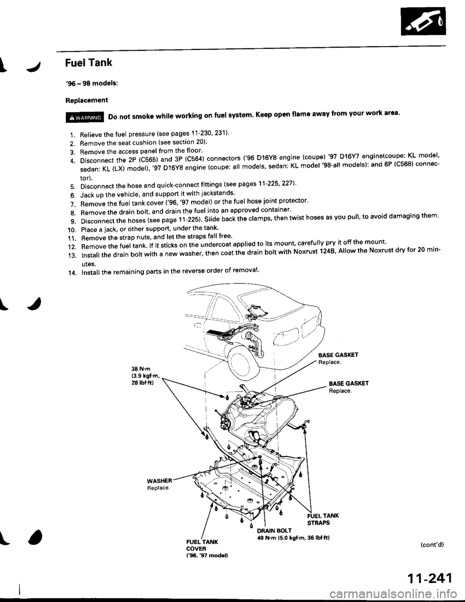
1. Relieve the fuel pressure (see pages \1-230' 23'll'
2. Remove the seat cushion (see section 20).
3. Remove the access panel from the floor'
4. Disconnect the 2P (C565) and 3P (C564) connectors ('96 D]6Y8 engine (coupe) '97 D16Y/ engine(coupe: KL model'
sedanKL(LX)model).'97D'l6YSengine(coupe:allmodels'sedan:KLmodel'98-allmodels):and6P(C568)connec-
tor),
5. Disconnect the hose and quick-connect fittings (see pag es'l'l-225' 2271
6. Jack up the vehicle, and support it with jackstands'
7. Removethefuel tank cover ('96,'97 model) orthefuel hose joint protector'
8. Bemovethedrain bolt,and drainthefuel into an approved container'
9. Disconnect the hoses {see page r i-izst. Sria" nu"i ihe clamps, then twist hoses as you pull, to avoid damaging them'
10. Place a jack. or other support, under the tank'
11. Remove the strap nuts, and let the straps fall free'
12. Removethefuel tank lf it sticks on the undercoat applied to its mount' caref u lly pry it off the mount'
13.|nsta||thedrainbo|twithanewwasher.thencoatthedrainbo|twithNoxrustl24B,A||owtheNoxrustdryfor20min-
ules.
14. Installthe remaining pans in the reverse order of removal'
SASE GASKETReplace.
BASE GASKETReplace.
!@@ Do not smoke while working on fuel system' Keep open flame away from your work ar'a'
TANKSTRAPS
DRAIN BOLT,19 N.m {5.0 kgt m, 36 lbf.ftl(cont'd)
11-241
Page 511 of 2189
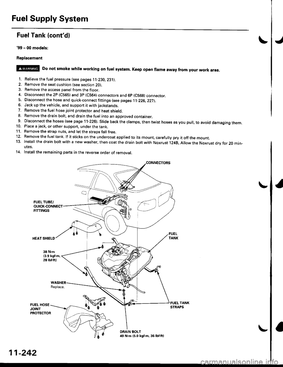
Fuel Supply System
Fuel Tank {cont'dl
39 - (xt models:
Replac6ment
o
@ Do not smoke whire working on fuer system. Ke€p open frama away trom your work area.
1. Relievethefuel pressure (see pages 11-230,23'll.
2. Remove the seat cushion lsee section 2O).3, Remove the access panel fromthefloor.
4. Disconnectthe2P (C565) and3P(CS64) connectors and 6p (C569) connecror.5. Disconnect the hose and quick-connect fiftings (see pages 1l-226,22j),6. Jack up the vehicle, and support it with jackstands.
7. Removethefuel hose joint protector and heat shield.8. Removethedrain bolt. and drainthefuel intoan aporoved container.9 Disconnect the hoses (see page 11-226). Slide back the clamps. then twist hoses as you pull, to avoid damagtng rnem.10. Place a jack, or other support, under the tank,11. Remove the strap nuts, and let the straps fallfree,'12. Removethefuel tank. lf itsticks onthe undercoat applied to its mount, carefully pry itoffthe mount.13. Install thedfain boltwith a new washer. then coat the d rain bolt with Noxrust 124B,Allowthe Nox.ust drv for 20 min-utes.
14. Installthe remaining parts in the reverse order of removal,
Replace.
DRAIN BOLT,19 N.m (5.0 kgf.m, 36lbf.ft)
11-242
Page 526 of 2189
![HONDA CIVIC 1997 6.G Workshop Manual \EGR VALVELIFT SENSOR#16 HOSE
I
(From page 11-256)
EGR VALVE LIFT SENSOR3P CONNECTOR lC14.l)
zF vcczI- . ] IYEL/BLU)ll 2l3l---l-r_ 7 |
v-,, ISG2IGRN/BLK) I ^ II{Vts
ECM CONNECTOR D {16P)
PUMP/GAUGE,0 HONDA CIVIC 1997 6.G Workshop Manual \EGR VALVELIFT SENSOR#16 HOSE
I
(From page 11-256)
EGR VALVE LIFT SENSOR3P CONNECTOR lC14.l)
zF vcczI- . ] IYEL/BLU)ll 2l3l---l-r_ 7 |
v-,, ISG2IGRN/BLK) I ^ II{Vts
ECM CONNECTOR D {16P)
PUMP/GAUGE,0](/manual-img/13/6068/w960_6068-525.png)
\EGR VALVELIFT SENSOR#16 HOSE
I
(From page 11-256)
EGR VALVE LIFT SENSOR3P CONNECTOR lC14.l)
zF vcczI- . ] IYEL/BLU)ll 2l3l---l-r_ 7 |
v-,, ISG2IGRN/BLK) I ^ II{Vts
ECM CONNECTOR D {16P)
PUMP/GAUGE,0 - 30 in.Hs4973X-041-XXXXX
sG2(GRN/BLKIvcc2IYEL/BLU}
Wire side ol temale terminals
PCM CONNECTORS C (31P}'
YES
Wire side of female terminals
1
(cont'd)
1-257
Check fo. a mallunction in theEGF valv€:1. ldove the vacuum pump/gauge
to the EGR valve.2. With the engine at idle, apply
26.7 kPa (200 mmHg,8.0 in.Hg)
ofvacuum to the EGR valve.
Does the engine stall or runrough and does the EGR valvehold vacuum?
Check for an open in the wire
IVCC2linel:1. Turn the ignition switch OFF.2. Disconnect the EGR valve liftsensor 3P connector.3. Turn the ignition switch ON (ll).
4. Measure voltage between theEGR valve lift sensor 3P con'
nector terminals No. 3 and
No.2.
ls lhere approx.5 V?
Check for an oDen in the wire
{VCC2 line}:Measure voltage between theECM/PCM connector terminalsD10 and Dl1 (C18 and C28)*.
Rep.ir open in the wire betweenrhe EGR valve snd ECM/PCM
{Dl0 {C28)*).lsthere approx.5 V?
Sub3titute t known-good ECM/PCM end recheck. lt 3ymptom/indication goos eway, replaceth6 original ECM/PCM.(To page 1l-258)*: '99 - 00 models