1997 HONDA CIVIC Connectors
[x] Cancel search: ConnectorsPage 445 of 2189
PGM-FI System
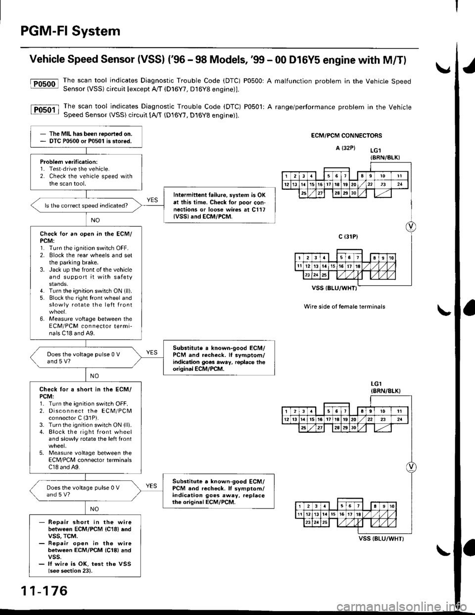
Vehicle Speed Sensor (VSSI ('96 - 98 Models,'99 - 00 D16Y5 engine with M/Tl
@The scan tool indicates Diagnostic Trouble Code (DTC) P0500: A malfunction problem in the Vehicle SpeedSensor (VSS) circuit Iexcept A!/T (D16Y7, D16Y8 engine)1.
The scan tool indicates Diagnostic Trouble Code (DTC) P0501: A range/performance problem in the VehicleSpeed Sensor (VSS) circuit [A,rT {D16Y7, D16Y8 engine)].
ECM/PCM CONNECTORS
A {32P} LG.t
VSS IBLU/WHT}
Wire side ot temale terminals
LGI(BRN/8LK}
The MIL has been reDorted on.DTC P0500 or P0501 is stored.
Problem verification:1- Test drive the vehicle.2. Check the vehicle speed withthe scan tool.
Intermittent tailure, system is OKat this time. Check tor Door con-nections or loose wires at C117{VSSland ECM/PCM.
ls the correct speed indicated?
Check for an open in the ECM/PCM:1. Turn the ignition switch OFF.2. Elock the rear wheels and setthe parking brake.3. Jack up the front of the vehicleand support it with safetystands.4. Turn the ignition switch ON (ll).
5. Block the right tront wheel andslowly rotate the left front
6, Measure voltage between theECM/PCM connector termi-nals C18 and A9.
Subslitute a known-good ECM/PCM and recheck. lf symptom/indic.tion goes away, replace theorisinal ECM/PCM.
Does the voltage pulse 0 Vand 5 V?
Check tor a short in ihe ECM/PCM:1. Turn the ignition switch OFF.2. Disco n n ect the ECM/PCMconnector C (31P).
3. Turn the ignition switch ON {ll).4. Block the right front wheeland slowly rotate the left front
5. Measure voltage between theECM/PCM connector terminalsC18 and A9.
Substitute a known-good ECM/PCM and recheck. lI symptom/indication goes away. replacethe original ECM/PCM.
Does the voltage pulse 0 Vand s V?
- Repair short in the wirebetwGen ECM/PCM {C18} endvss, TcM.- Repair open in the wirebetween ECM/PCM {Cl8} andvss.- lf wire is OK, test the VSSlsee section 23).
{BRN/BLK}
239l0lt
121611t8t9202321
2A2930
c {31P}
I38191o
tl12ialr5i6l10./
I2356a9l011
12l3l5t61tl8t920222a
27202930
12910
t2l13l.l7I l,/ 1,/231r.lslt., ),rlL
VSS {BLU/WHT}
11-176
Page 446 of 2189

fFosoo-l
lFosoil
Vehicle Speed Sensor (VSS) ('99 - 00 Models except Dl6Y5 engine with M/T)
Thescantoo|indicatesDiagnosticTroub|ecode(DTc)Po5o0:Ama|functionproblemintheVehic|espeed
Sensor (VSS) circuit lexcept A//T (D16Y/, D16Y8 engine)l'
Thescantoo|indicatesDiagnost|cTroub|eCode(DTC)Po5o1:Arange/performanceprob|emintheVehicle
SDeed Sensor {VSS) circuit tA,/T (D16Y7, D16Y8 engine)1.
ECM/PCM CONNECTORS
B {25P)
I
t
Wire side ol lemale terminals
ECM/PCM CONNECTORS
B E5PI
The MIL has been reported on
OTC P0500 or P0501 is stored.
Problem veritication:1. Test-drive the vehicle.
2. Check the vehicle speed with
the scan tool
lntermitt6nt failure, sYstem is OK
at thb time. Check tor Poor con-
nections or loose wir6 at C117
{vss} .nd ECM/PCM
ls the correct sPeed indicated?
Check for an open in the ECM/
PCM:1. Turn the ignition switch OFF.
2. Block the rear wheels and set
the parking brake
3. Jack uP the front ofthe vehicle
and support it with safety
stands.4. Turn the ignition switch ON (ll).
5. Block the right front wheel and
slowly rotate the left front
6, Measure voltage between the
ECM/PCM connector termi_
nals C23 and 820.
Substituto a known'good ECM/
PcM and rech€ck. ll sYmptom/
indic€tion goes awaY, lsplace the
original ECM/PCM.
Does the voltage Pulse 0 V
and 5 V or battery voltage?
Check for a short in the ECM/
PCM:1. Turn the ignition switch OFF.
2. Disco n n ect the EcM/PcM
connector C (31P).
3. Turn the ignition switch ON (ll)
4. Block the right front wheel
and slowly rotate the left front
5. Measure voltage between the
ECM/PCM connector terminals
C23 and 820.
Substiiute . known-good ECM/
PCM and r6check. lf symptom/indication goes awaY, rePlace
the origin.l ECM/PCM.
Does the voltage Pulse 0 V
and 5 V or battery voltage?
- Reoair short in the wire
between ECM/PCM {C23} and
vss. TcM.- Repai. open in the wire
between ECM/PCM {C231 andvss.- lf wire is OK, tesr the VSS
{see sestion 23).
Wire side oI female terminals
11-177
Page 451 of 2189
PGM-FI System
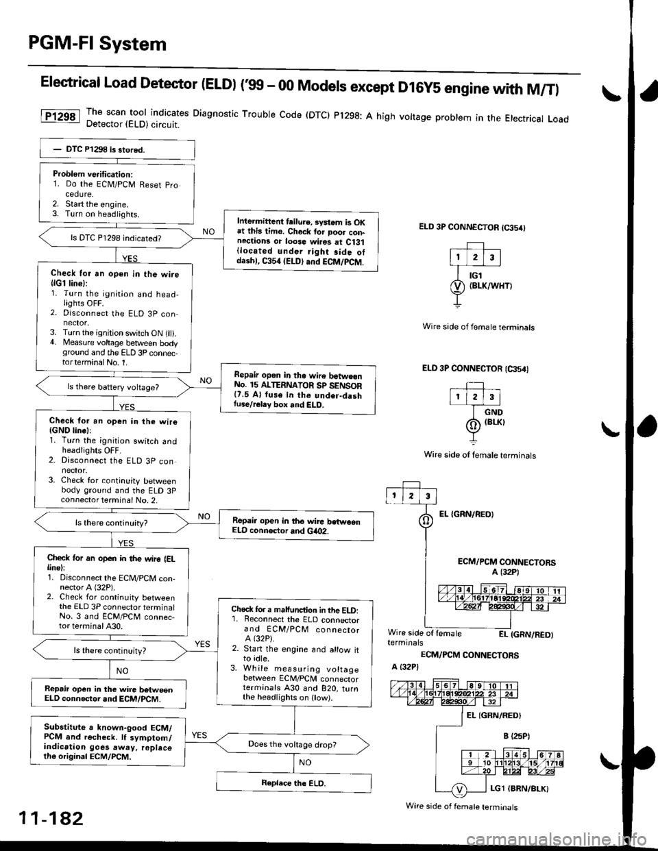
Elestrical Load Detector (ELDI ('99 - 00 Models except D16y5 engine with M/Tl
The scan tool indicates Diagnostic Trouble code (DTCI Pl298: A high vottage problem in the Etectrical LoadDetector (ELD) circuit.
ELD 3P CONNECTOR (65/0
EL {GRN/REOI
Wire side of fernale terminals
ELD 3P CONNECTOR (CA54I
TIr l2l3l
I crvo
(o) (BrKr
Y
Wire side of lemale terminals
ECM/PCM CONNECTORSA (32P1
Wire side of lemaleEI- IGRN/RED)terminals
ECM/PCM CONNECTORS
A {32P)
Problem ve.itication:1. Do the ECN4/PCM Reset pro
cedure.2. Start the engine.3- Turn on headiights.Inte.mittent teilu.e, svstem is OKat this lime. Chock for Door con-nections or loose wires at Ci31{located under Jight side otdaihl, C354 (ELD) and ECM/PCM.
ls DTC P1298 indicated?
Check for an open in the wire{lG1 line}:1. Turn the ignition and head-lights OFF.2. Disconnect the ELD 3P con
3. Turn the ignition switch ON (ll).4. Measure voltage between bodyground and the ELD 3P connec-torterminalNo. 1.
Repair opon in tho wiro batwe€nNo. 15 ALTERNATOR Sp SENSOR{7.5 A} fuse in th6 undor-dashIuse/reley box and ELD.
ls there battery voltage?
Check for an open in the wiro{GND linel:1. Turn the ignition switch andheadlights OFF.2. Disconnect the ELD 3P connector.3. Check for continuity betweenbody ground and the ELD 3Pconnector terminal No. 2,
Repair open in the wire bstwoenELD connsctor and Gia02.
Check ,or an open in the wire IELlinel:1. Disconnect the ECM/PCM con-nector A (32P).2. Check for continuity betweenthe ELD 3P connector terminalNo. 3 and ECM/PCM connec-tor terminal A30.
Chock fo. a malfunction in the ELD:'1. Reconnect the ELD connectorand ECM/PCM connectorA (32P).
2. Stan the engine and allow itto idle.3. While measuring voltagebetween ECM/PCM connectorterminals A30 and B2O, turnthe headlighrs on ow).
ls there continuity?
Repsir op€n in the wire betweenELD connector and ECM/PCM.
Substitute a known-good ECM/PCM and recheck. lf symptom/indication goes away. replacelh6 original ECM/PCM.
Does the vokage drop?
Wire side of f€male terminals
11-182
Page 471 of 2189
ldle Control System
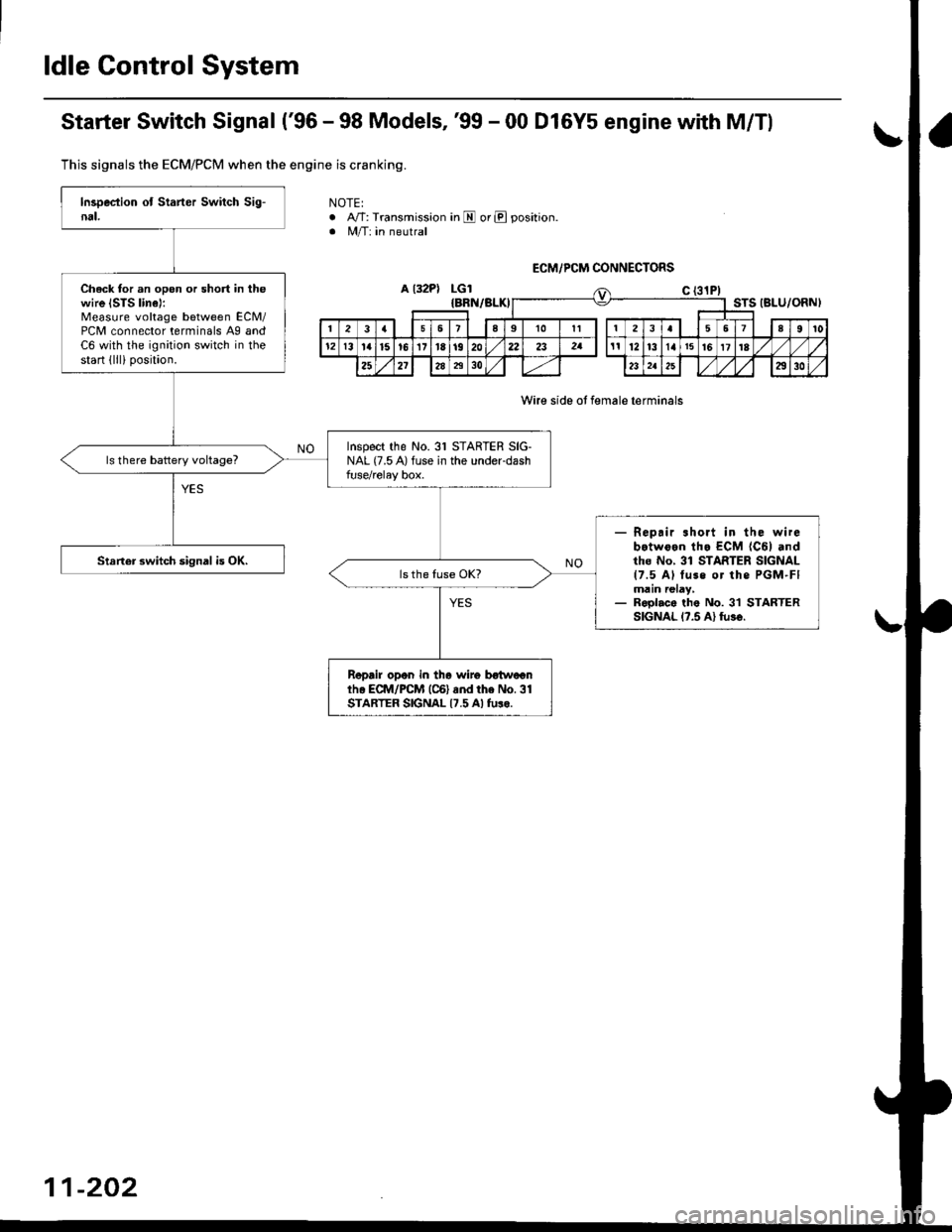
Starter Switch Signal ('96 - 98 Models,'99 - 00 D16Y5 engine with M/Tl
Thjs signals the ECM/PCM when the engine is cranking.
NOTE:. A/T: Transmission in E or E position. M/T: in neutral
a l32PlLGl
Wire side ot female lerminals
Check tor an open or short in thewire ISTS linel:Measure voltage between ECM/PCM connector terminals A9 andC6 with the ignition switch in thestart lllli position.
Inspect the No. 31 STARTER SIG-NAL (7.5 A) fuse in the underdashfuse/relay box.
- Repair .hort in the wirebotwoen tha ECM {C6l andtho No, 31 STARTER SIGNAL{7.5 Al tuss or the PGM-FImain relay,- Roolac. the No. 3'l STARTERSIGNAL l?.5 Al tu3€.
Staner 3witch signal is OK.
Repair opon in th6 wiro botweanih. ECII4/PCM (C6) and the No.31STARTER SIGNAL {7.5 Al tulo.
ECM/PCM CONNECTORS
{BRN/BLKISTS IBLU/ORNI
216910It3567a9l0
l2l3la15!6171a1920222att12t3l4t5t6171E
252l2A7t30232a2930
11-202
Page 472 of 2189

\
Starter Switch Signal ('99 - 00 Models except Dl6Y5 engine with M/T)
NOTE:. M/f: Clutch pedal must be depressed.. A,/T: Transmission in E or E position
ECM,/PCM CONNECTORS
I
This signals the ECM/PCM when the engine is cranking
Ch€ck for an open or short in the
wire {STS linel:Measure voltage between ECM/PC[/| connector terminals A24
and 820 with the ignition switch
in the start position (lll).
Inspect the No.31 STARTER SIG-NAL (7.5 Alluse in the under-dash
- Repair 3hort in tho wire be'
tween tho ECM/PCM lA24)and tho No. 31 STARTER SIG-NAL 17.5 Al fuse or the PGM-FImein relay.- ReDlaco the No. 31 STARTERSIGNAL 17.5 Al fuse.
Staner 3witch signal is OK.
Repair open in the wirc betwean
the ECM/PCM lA24) and the No.
31 STARTER SIGNAL {7.5 Alfuse.
W;re side of female terminals
Page 473 of 2189
ldle Gontrol System
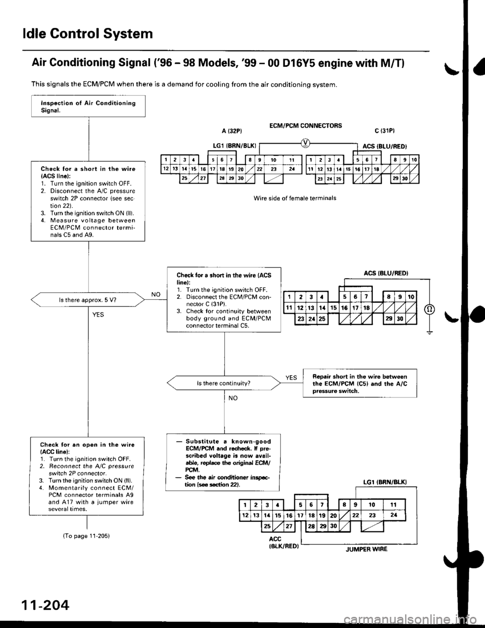
Air Gonditioning Signal ('96 - 98 Models, '99 - 00 Dl6Y5 engine with M/Tl
a {32P1ECM/PCM CONNECTORS
Wire side of female terminals
c l3lPl
This sjgnals the ECM/PCM when there is a demand for cooling from the air conditioning system.
(To page 11-205)
Check for a short in the wire{ACS line):1. Turn the ignition switch OFF.2. Disconnect the A/C pressure
switch 2P connector {see section 22).3. Turn the ignition switch ON (ll).
4. Measure vo lta ge betweenECM/PCM connector termi-nals C5 and A9.
Check for a .hort in the wi.e {ACSline):1. Turn the ignition switch OFF.2. Disconnect the ECM/PCM con-nector C (3lPi.
3. Check tor continuity betweenbody ground and ECM/PCMconnector terminal C5,
ls there approx. 5 V?
Reotir short in the wi.e betweenthe ECM/PCM lc5l and rhe A/Cpressure switch.
ls there continuity?
- Substitute a known-goodECM/rcM .nd re.fieck. f Dre-scribed voltage is now availtble, replace the original ECft4/PCM,- See the air conditioner inspe-tion ls€e s€ction 221.
Check tor an op€n in the wireIACC lin6l:1. Turn the ignition switch OFF.2. Reconnect the A/C pressure
switch 2P connector.3. Turn the ignition switch ON (ll).
4. Momentarily connect ECM/PCM connector terminals A9and A17 with a jumper wire
LGl IBRN/8LKIACS {BLU/RED)
2361I9't0Itt3a89t0
12't31al5l617t8t920232all12l3l!ai5!617'tE
252l2A2930232a252930
ACS (BLU/BEDI
LGl IBRN/BLKI
123aslslrl lolgl ro lrr I
121314l516y)nltslnl/@) zr I zr I
25271!M1 1-/r
ACC
11-204
IBLK/RED)JUMPER WIRE
Page 474 of 2189
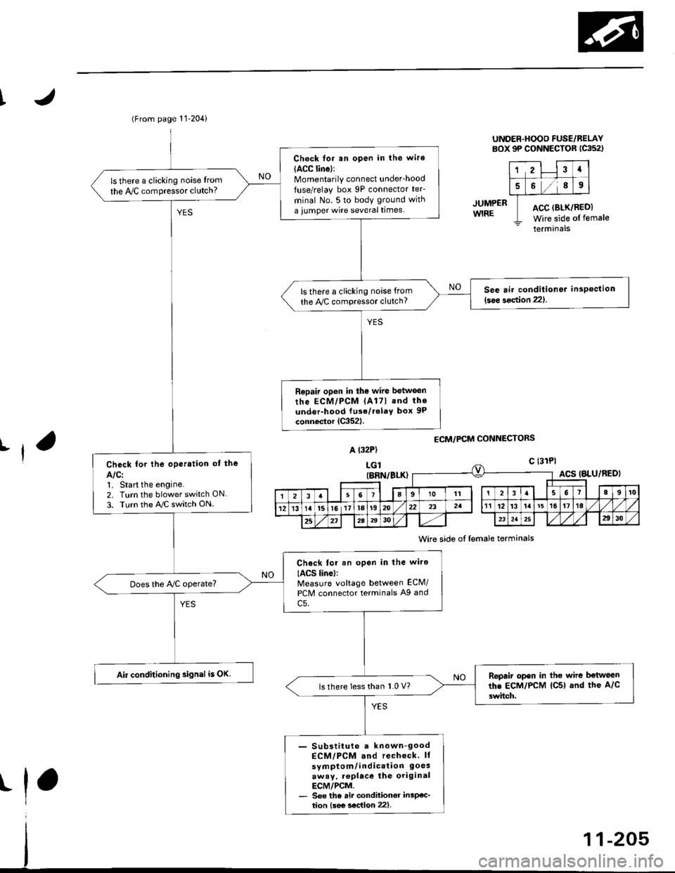
(From page 11-204)
Check for an open in the wir€(ACC linel:Momentarily connect underhood
fuse/relay box 9P connector teF
minal No. 5 to body ground with
a iumper wire several times.
ls there a clicking noise from
the IVC compressor clutch?
See air conditionor inspection(see 3oction 221.ls there a clicking noise from
the Py'C compressor clutch?
Repair open in the wire between
rhe ECM/PCM lAl7l and th6
under-hood fu3e/rolaY box 9P
connector lC352l.
Check for the oPeration of the
Alcl1. Start the engine.2. Turn the blower switch ON
3. Turn the AJC switch ON.
Chock tor an open in the wire
IACS linel:Measure voltage between ECM/
PCM connector terminals A9 and
c5.
Does the Ay'C operate?
Air conditioning signal is OK.Repair open in the wire b€tweenthe EcM/PcM lC5) and the A/c
3witch.ls there less than 1.0 V?
- Substiiute a known-goodECM/PCM and recheck ll
symptom/indication 9oesaway, .oplace the originalECM/PCM.- See the air condhioner insP€c_tion {see s€c{ion 22).
UNDER.HOOD FUSE/BELAYBOX 9P CONNECTOR 1C352)
12Ia
589
ACC (BLK/RI
Wire side ofACC (BLK/REDI
Wire side of female
terminals
JUMPERWIRE
ECM/PCM CONNECTORSrfA t32P)
LGlc {31Pl
t
(BRN/BLK)ACS IBLU/RED)
I23a9101t3I89t0
121315l611la1920232att12't3la't5t617ta
25272A2930232a2930
Wire side of lemale terminals
Page 475 of 2189
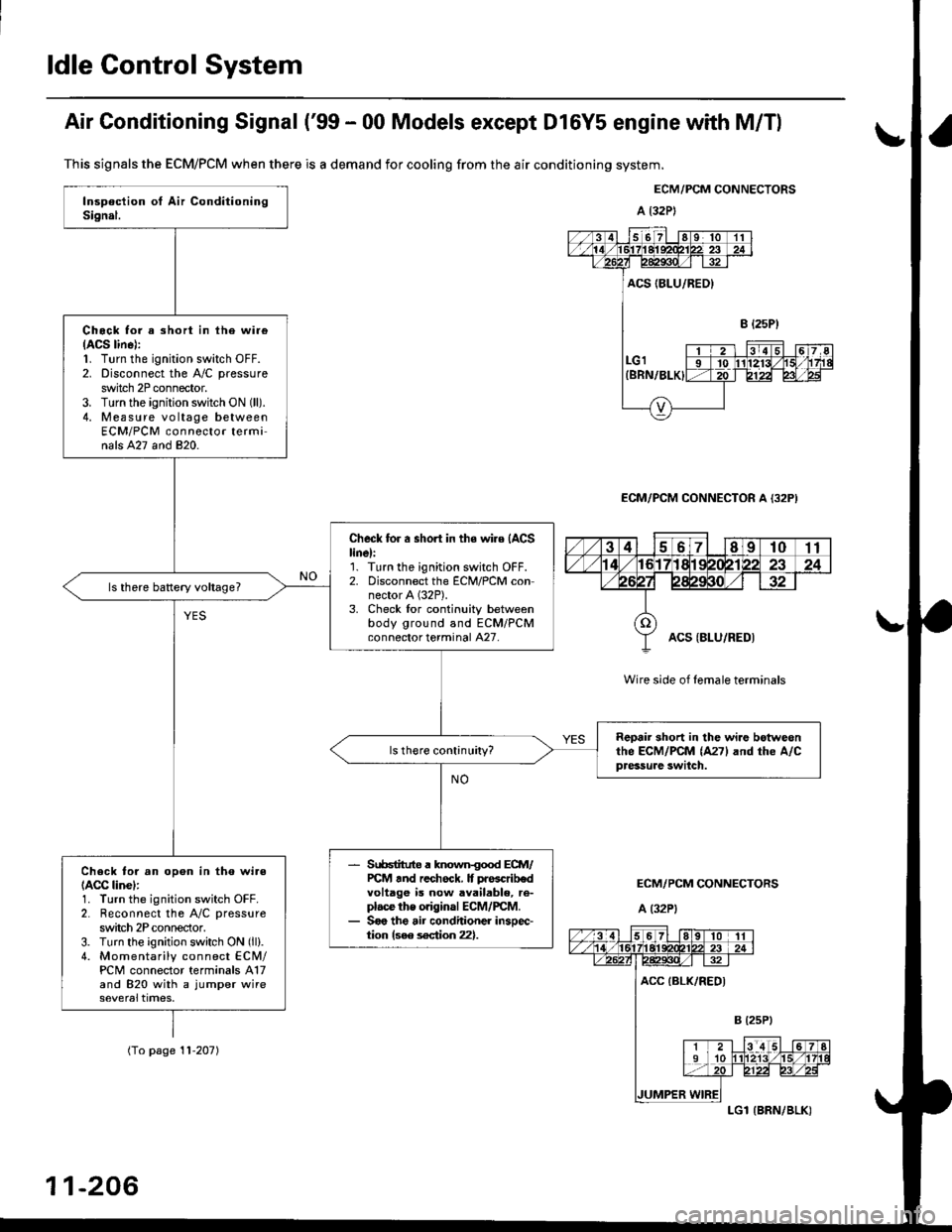
ldle Control System
Air Conditioning Signal ('99 - 00 Models except Dl6Y5 engine with M/Tl
This signals the ECM/PCM when there is a demand for cooling from the air conditioning system.
ECM/PCM CONNECTORS
a l32P)
ECM/PCM CONNECTOR A {32P)
Wire side of female terminals
ECM/PCM CONNECTORS
A (32P1
Chock tor a short in ihe wi.e(ACS lin6):1. Turn the ignition switch OFF.2. Disconnect the A/C pressure
switch 2P connector.3. Turn the ignition switch ON (ll).
4. Measure vo ltage betweenECM/PCM connector terminals A27 and 820.
Check for a short in the wire (ACS
linel:'1. Turn the ignition switch OFF.2. Disconnect the ECM/PCM connector A (32P).
3. Check lor continuity betweenbody ground and ECM/PCMconnector terminal A27.
Reoair short in lhe wi.e botweonthe ECM/PCM (A271 and rhe A/Cpressure swilch.
Srr66tituto a known{ood ECM/PCt4 tnd rechock. It prascrib€dvoltage is now available, re-plac€ the original ECM/rcM.Soo the air conditioner insoec-tion {see s€ction 22}.
Check to. an opon in tho wi.e(ACC linel:1. Turn the ignition switch OFF.2. Reconnect the A/C pressure
switch 2P conneclor.3. Turn the ignition switch ON (ll).
4. Momentarily connect ECN4/PCM connector terminals A17and 820 with a jumper wire
(To page '! 1-207)
11-206
LGl {BRN/BLK)