Page 1504 of 2189

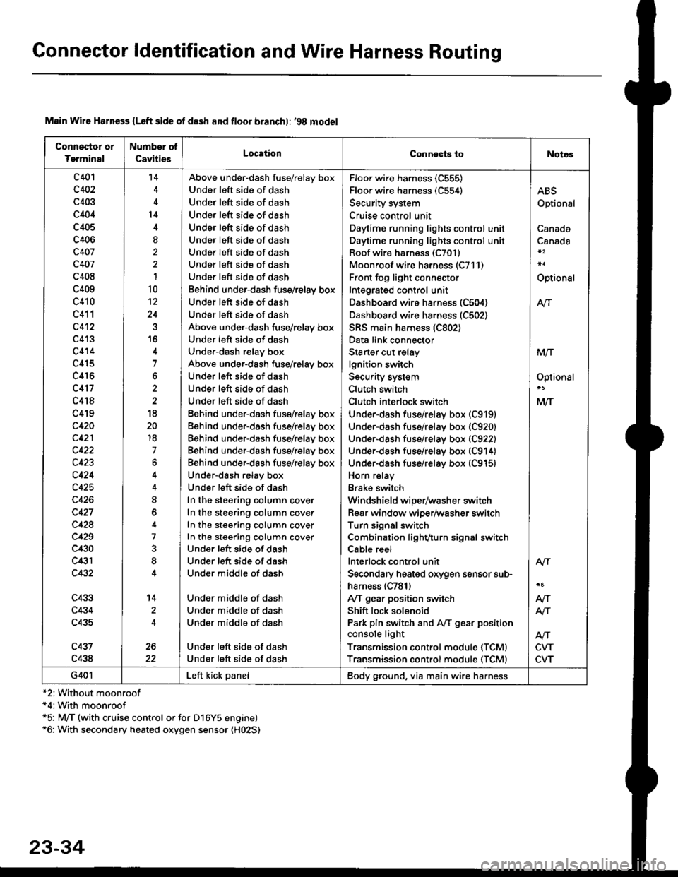
Connector ldentification and Wire Harness Routing
Connoctor or
Tgrminal
Number of
CavitiesLocationConneqts toNot€s
c401
c402
c403
c404
c405
c406
c407
c407
c408
c409
c410
c411
c4't2
c413
c414
c415
c416
c417
c418
c419
c420
c421
c422
c423
c424
c425
c426
c427
c428
c429
c430
c431
c432
c433
c434
c435
c437
c438
't4
l4
8,
1
10
12
24
7
6
18
20
18
7
6
8
7
8
14
2
Above under-dash fuse/relay box
Under left side of dash
Under left side of dash
Under left side of dash
Under left side of dash
Under left side of dash
Under left side of dash
Under left side of dash
Under left side of dash
Behind under-dash fuss/relay box
Under left side of dash
Under left side of dash
Above under-dash fuse/relay box
Under left side of dash
Under-dash relay box
Above under-dash fuse/relay box
Under left side of dash
Under left side of dash
Under left side of dash
Eehind under-dash fuse/relay box
Behind under-dash fuse/relay box
Behind under-dash fuse/relay box
Behind under-dash fuse/rslay box
Behind under-dash fuse/relay box
Under-dash relay box
Under left side of dash
In the steering column cover
In the steering column cover
In the steering column cover
In the steering column cover
Under left side of dash
Under left side of dash
Under middle of dash
Under middle of dash
Under middle of dash
Under middle of dash
Under left side of dash
Under left side of dash
Floor wire harness (C555)
Floor wire harness (C554)
Security system
Cruise control unit
Daytime running lights control unit
Daytime running lights control unit
Roof wiro harness (C7011
Moonroof wire harness (C711)
Front fog light connector
Integrated control unit
Dashboard wire harness (C504)
Dashboard wire harness (C502)
SRS main harness (C802)
Data link connector
Starter cut relay
lgnition switch
Security system
Clutch switch
Clutch inlerlock switch
Under-dash fuse/relay box (C919)
Under-dash fuse/relay box (C920)
Under-dash fuse/relay box (C922)
Under-dash fuse/relay box (C914)
Under-dash fuse/relay box (C915)
Horn relay
Brake switch
Windshield wiper/washer switch
Rear window wiper/washer switch
Turn signal switch
Combination light/,turn signal switch
Cable reel
lnterlock control unit
Secondary heated orygen sensor sub-
harness (C781)
Ay'T gear position switch
Shift lock solenoid
Park pin switch and Aff gear position
console light
Transmission control module (TCMI
Transmission control module (TCM)
ABS
Optional
Canada
Canada
Optional
M
MIT
Optionsl
MlT
Alr
NT
NT
CVT
CVT
G401Left kick panelBody ground, via main wire harness
Main Wire Harn€ss {Left side ot dash and floor branchl: '98 model
*2: Without moonroof*4:With moonroof*5: M/T (with cruise control or for D16Y5 engine)*6: With secondary heated oxygen sensor (H02S)
23-34
Page 1535 of 2189

lr-
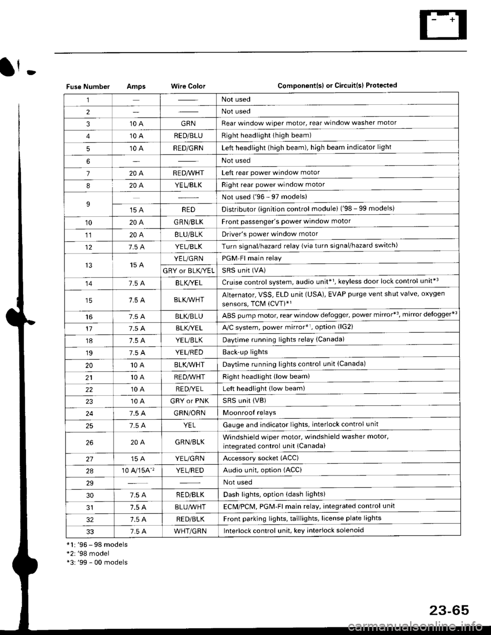
Fuse NumberAmpswire ColorComponent{sl or Circuit(sl Protected
*1r '96 - 98 models*2r '98 model*3: '99 - 00 models
,lNot used
2Not used
310 AGRNRear window wioer motor, rear window washer motor
410 ARED/BLURight headlighr thigh beam)
510 ARED/GRNLeft headlight (high beam), high beam indicator light
6Not used
7204R E D/VVHTLeft rear power window motor
820A.YEUBLKRight rear power window motor
9Not used ('96 - 97 models)
't5 AREDDistributor (ignition control module) ('98 - 99 models)
10204G RN/BLKFront passenger's power window motor
1120ABLU/BLKDriver's power window motor
127.5 AYEUBLKTurn signal/hazard relay (via turn signal/hazard switch)
t515 AYEL/GRNPGM-Fl main relay
GRY or BLK,^/ELSRS u nit (VA)
141.54B LK/YE LCruise control system, audio unit*1, keyless door lock control unit*3
BLK/lr'r'HTAlternator, VSS, ELD unit (USA), EVAP purge vent shut valve, oxygen
sensors, TCM (CVT)*'
t6BLI(,/BLUABS pump motor, rear window defogger. power mirror*3, mirror delogger*3
177.5 ABLK,/YE LA,/C system, power mirror*r. option (lG2)
18YEUBTKDaytime running lights relay (Canada)
197.5 AYEUREDBack'up lights
2010ABLK/VVHTDaytime running lights control unit (Canada)
2110 AREDA/VHTRight headlight (low beam)
2210 ARE DI/E LLeft headlight (low beam)
10 AGRY or PNKSRS UNit (VB)
247.5 AGRN/ORNMoonroof relays
257.5 AYELGauge and indicator lights. interlock control unit
204GRN/BLKWindshield wiper motor, windshield washer motor,
integrated control unit {Canada)
15 AYEL/GRNAccessory socket (ACC)
2a10 A,/'�]5A''YE L/R EDAudio unit, option (ACC)
29Not used
307.5 AR ED/BLKDash lights, option (dash lights)
1.5 ABLUA/VHTECM/PCl\4, PGM-Fl majn relay, integrated control unit
RED/BLKFront parking lights, taillights, license plate lights
337.5 AWHT/GRNlnterlock control unit. key interlock solenoid
23-65
Page 1572 of 2189
lgnition System
Component Location Index
IGNITION TIMING CONTROL SYSTEM
. Troubleshooting, section 11
. ldle speed Inspection/Adjustment. section 11
. Inspection and Setting, page 23-105
SERVICE CHECK CONNECTOR {2P}Iwiie colors: 8RN and BLKI
TEST TACI{OMETER CONNECTOB
IGNITION WIRESlnspection and Test, page 23-110
PLUGSInspection, page 23 1 11
Replacement, page 23'106Overhaul, page 23-107lgnition Coil Test, page 23'110lgnition Control Module llCM)Input Test, page 23-109
23-102
Page 1577 of 2189
el -Distributor Overhaul
HITACHI:
TOC/CKP/CYP
DISTRIBUTOR IGNITION {DI} HOUSINGCheck for cracks and damage.
Troubleshooting, section 1 1
Do not disassemble.
CAP SEALCheck for damage.
IGNITION CONTROL MODULE (ICMI
Input Test, page 23'109
IGNITION {DI) CAP
Check for cracks, wear,damage, and fouling.Clean or replace,
{cont'd)
23-107
Test, page 23_110
Page 1578 of 2189
lgnition System
Distributor Overhaul (cont'dl
TEC:
IGNITION CONTROLMODULE IICM'Input Test, page 23-1
DISTRIBUTOR IGNITION {DI} HOUSINGCheck for cracks and damage.
COVER
DISTRIBUTOR IGNITION IDI) ROTOB
CAP SEALCheck for damage.DISTRIBUTOR IGNITION {DII CAPCheck for cracks, wear,damage, and fouling.Clean or replace,
IGNITION COILTest, page 23-110
O-RINGReplace
\
I
@
TDC/CKP/CYP S€NSORTroubleshooting, section 1 1Do not disassemble.
WHT/BLU
23-104
Page 1579 of 2189

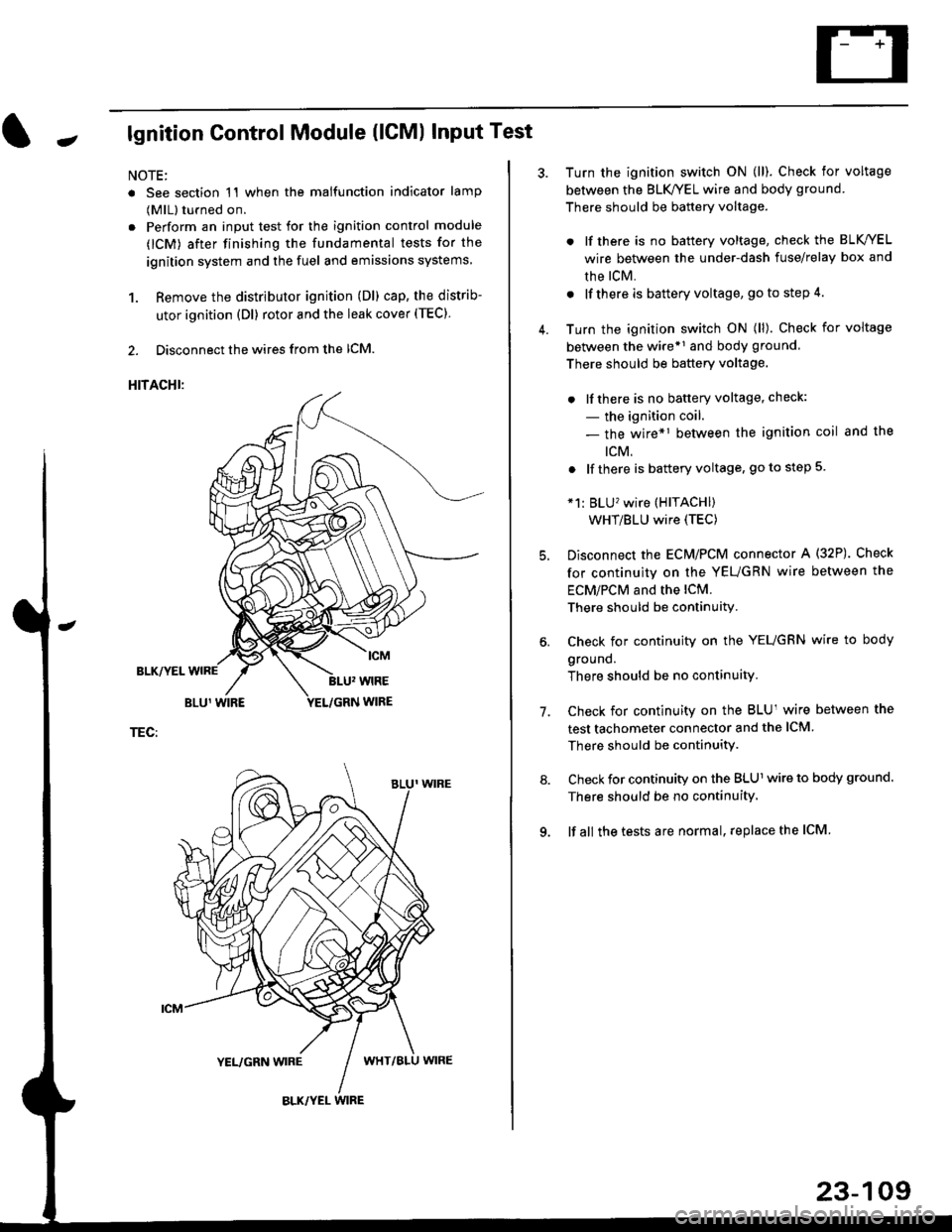
Jlgnition Control Module (lCMl Input Test
NOTE:
. See section 1'l when the malfunction indicator lamp
(MlL) turned on.
. Perform an input test for the ignition control module
(lCM) after finishing the fundamental tests for the
ignition system and the fuel and emissions systems
1. Remove the distributor ignition (Dl) cap, the distrib-
utor ignition (Dl) rotor and the leak cover (TEC).
2. Disconnect the wires from the lCM.
HITACHI:
BLK/YEL
TEC:
Turn the ignition switch ON (ll). Check for voltage
between the BLK/YEL wire and body ground.
There should be battery voltage.
. lf there is no battery voltage, check the BLK/YEL
wire between the under-dash fuse/relay box and
rhe lcM.
. lf there is battery voltage, go to step 4.
Turn the ignition switch ON (ll). Check for voltage
between the wire*r and body ground
There should be battery voltage.
. lfthere is no battery voltage, check:
- the ignition coil.
- the wire*1 between the ignition coil and the
tcM.
. lf there is battery voltage, go to step 5
*1: BLU'�wire (HITACHI)
WHT/BLU wire (TEC)
Disconnect the EcM/PCM connector A (32P). Check
for continuity on the YEUGRN wire between the
ECM/PCM and the lCM.
There should be continuity.
Check for continuity on the YEUGRN wire to body
ground.
There should be no continuity.
Check for continuity on the BLUl wire between the
test tachometer connector and the ICM
There should be continuitY.
Check for continuity on the BLUl wire to body ground.
There should be no continuity.
lf all the tests are normal, replace the ICM
7.
23-109
Page 1599 of 2189
JGau ge/lndicator/Terminal
With tachometer;
CONNECTOR "A"
{A/T GEAR POSITION INDICATOR}
Location lndex
CONNECTOR "8"
{GAUGE and INOICATOR)CONNECTOB "C"
CONNECTOR "D"
{ABS INDICATORI
SPEEDOMETER:Indicates 60 km/h at 637 rpm or
60 mph at 1,025 rpm o{thevehicle speed sensor (VSS).
A/T GEAR POSITIONINDICATORSee page 23 149
TACHOMETER:Indicates 100 rpm at200 pulses per minuteol the ignition controlmodule (lCMi.FUEL GAUGEENGINE COOLANT TEMPERATURE (ECT) GAUGE
(cont'd)
23-129
(GAUGE end INDICATORI
A1-----------+816
JlltlllulllllrL
c1 --------->c13
1ililil{ilrL
oooo o 0006^
)og @ @ o^o @ )'l |. o
Fl- - -> F5E1_ _ -->E5D1- --+05
oo/ \oo
Gauge/Sending Unit Test, page 23-142
Page 1602 of 2189
Gauge Assembly
(Wnh lachomolgr)
I cNfldt--]I CONTRoL II MODULE
I 0cM) :
tvl
i.ll
|
-i;,
i
TURN SIGNAUHAZAROWARNINGswtTcH
Circuit Diagram {cont'd)
Fh"lurous @)- BLrcwHT + BLKryEL
fi'Sfvrous 16r.- veLPAGE
RIGHT
V
IGR&ryE
LEFT
V
I
No.s (104)FUSE
V
IBEO/GRN
lru
8LU4RE0
ABSCONTROLUNIT
-rl
eLui'rvrr
G401G402G401G442
23-132