1997 HONDA CIVIC Control Module AT
[x] Cancel search: Control Module ATPage 691 of 2189

Electronic Control SYstem
The electronac controt system consrsts of a Powertrain control Module (PcM), sensors, a Iinear solenoid and four solenoid
valves, shifting and lock-up are electronically controlled for comfortable driving under all conditions The PCM is located
below the dashboard, under the front lower panel on the passenger's side
PGM-FIControl Sy3tem
A/T Control SYstom
Shift Control
Lock-uD Control
14-13
Page 717 of 2189
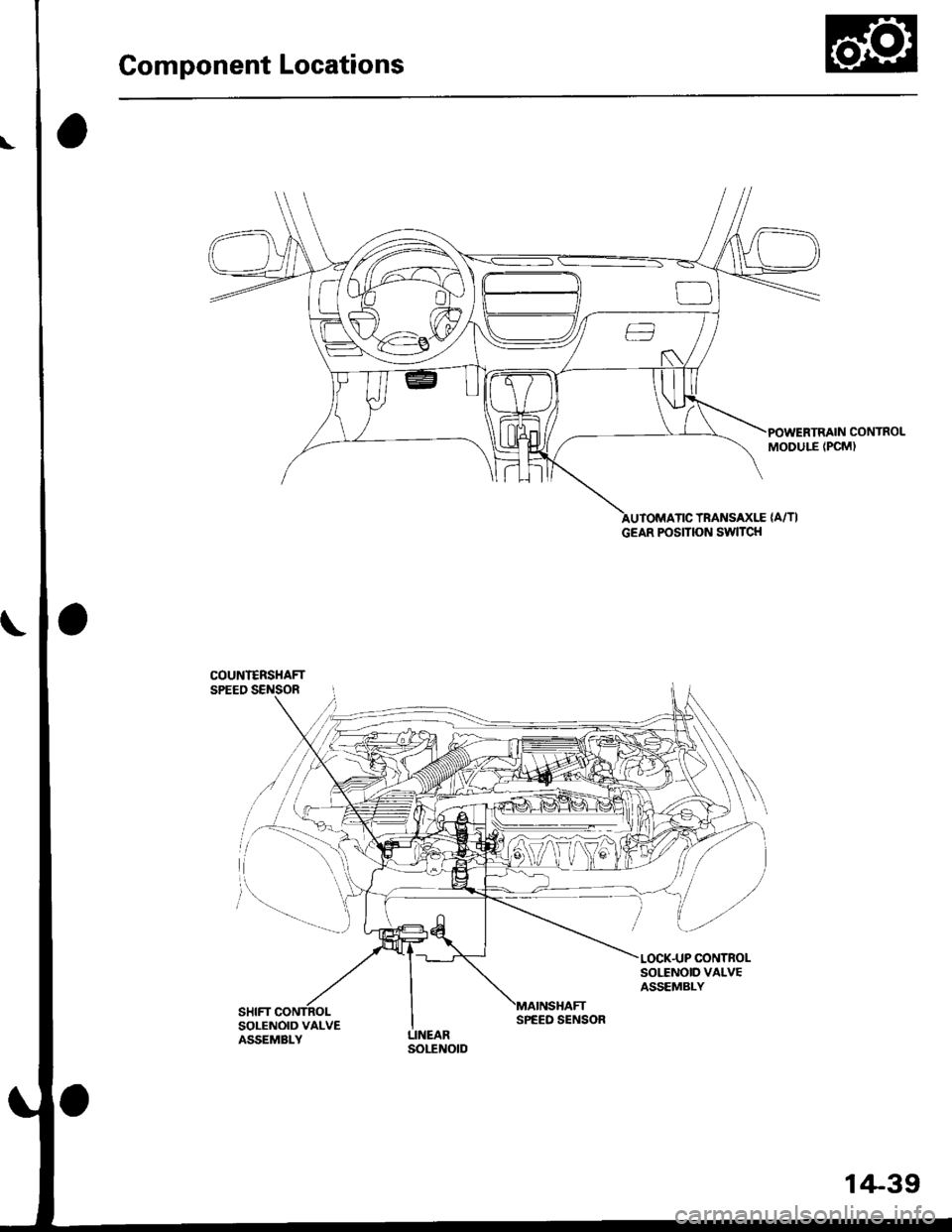
Component Locations
POWERTRAIN CONTROLMODULE (PCM)
TRANSAXLE {A/TI
COUNI€RSHAFTSPEED SENSOR
SOI,TNOID VALVEASSEMBLY
SOLENOID VALVEASSEMBLY
GEAR POSITION SWITCH
SPEED SENSOR
1+39
Page 873 of 2189

Description
The Continuously Variable Transmission (CVT) is an electronically controlled automatic transmission with drive and driv
en Oullevs, and a steel belt. The CVT provides non stage speeds forward and one reverse. The entire unit is positioned in
line with the engine.
Transmission
Around the outside of the flywheel is a ring gear which meshes with the starter pinion when the engine is being staned.
The transmission has four parallel shafts: the input shaft, the drive pulley shaft. the driven pulley shaft, and the secondary
gear shaft. The input shaft is in line with the engine crankshaft. The drive pulley shaft and the driven pulley shaft consist of
movable and fixed face pulleys. Both pulleys are linked by the steel belt.
The input shaft includes the sun gear. The drive pulley shaft includes the forward clutch which mounts the carrier assem-
bly on the forward clutch drum. The carrier assembly includes the pinion gears which mesh with the sun gear and the ring
gear. The ring gear has a hub-mounted reverse brake disc.
The driven pulley shaft includes the start clutch and the secondary drive gear which is integral with the park gear' The sec-
ondary gear shaft is positioned between the secondary drive gear and the final driven gear. The secondary gear shaft
includes the secondary driven gear which serves to change the rotation direction. because the drive pulley shaft and the
driven oullev shaft rotate the same direction. When certain combinations of planetary gears in the transmission are
engaged by the clutches and the reverse brake, power is transmitted from the drive pulley shaft to the driven pulley shaft
to provide E, E, E, and El.
Electronic Control'96 - 98 Models:
The electronic control system consists of the Transmission Control Module (TCM), sensors, three linear solenoids, and a
inhibitor solenoid. Shifting is electronically controlled under all conditions'
The TCM is located below the dashboard, behind the kick panel on the driver's side.'99 - 00 Models:
The electronic control svstem consists of a Powertrain Control Module (PCM), sensors, three linear solenoids and an
inhibitor solenoid. Shifting is electronically controlled under all conditions. A Grade Logic Control System to control shift-
ing in E position while the vehicle is ascending or descending a slope.
The PCM is located below the dashboard, under the kick panel on the passenger's side.
Hydraulic Control
The lower valve body assembly includes the main valve body, the Pressure Low (PL) reguiator valve body, the shift valve
body, the start clutch control valve body, and the secondary valve body. They are positioned on the lower part of the
transmission housing.
The main valve body contains the Pressure High (PH) control valve, the lubrication valve, and the pitot regulator valve.
The secondary valve body contains the PH regulator valve, the clutch reducing valve, the start clutch valve accumulator,
and the shift inhibitor valve. The PL regulator valve body contains the PL regulator valve and the PH-PL control valve
which is ioined to the PH,PL control linear solenoid. The inhibitor solenoid valve is bolted on the PL regulator valve body.
The shift valve body contains the shift valve and the shift control valve. which is joined to the shift control linear solenoid.
The start clutch control valve body contains the start clutch control valve, which is joined to the start clutch control linear
solenoid. The linear solenoids and the inhibitor solenoid are controlled by the TCM or PCM. The manual valve body which
contains the manual valve and the reverse inhibitor valve, is bolted on the intermediate housing.
The ATF pump assembly is located on the transmission housing, and is linked with the input shaft by the sprockets and
the sprocket chain. The pulleys and the clutch receive fluid from their respective feed pipes, and the reverse brake receives
fluid from internal hydraulic circuit.
Shift Control Mechanism
Input from various sensors located throughout the vehicle determines which linear solenoid the TCM or PCM will activate.
Activating the shift control linear solenoid changes the shift control valve pressure, causing the shift valve to move. This
pressurizes the drive pulley pressure to the drive pulley and the driven pulley pressure to the driven pulley and changes
their effective pulley ratio. Activating the start clutch control linear solenoid moves the start clutch control valve. The start
clutch control valve uncovers the port, providing pressure to the start clutch to engage it(cont'd)
14-195
,!
Page 881 of 2189
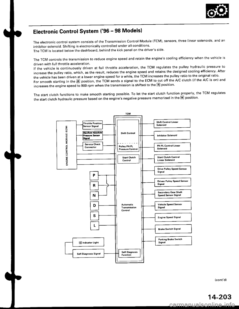
Electronic Control System ('96 - 98 Modelsl
The electronic control system consists of the Transmission control Module (TcM), sensors, three linear solenoids, and an
inhibitor solenoid. Shifting is electronically controlled under all conditions
The TCIM is located below the dashboard, behind the kick panel on the driver's side'
The TcN4 controls the transmission to reduce engine speed and retain the engine's cooling efficiency when the vehicle is
driven with Iull throttle acceleration
lf the vehicle is continuously driven at full throttle acceleration, the TCM regulates the pulley hydraulic pressure to
increase the pulley ratio, which, as the result. reduces the engine speed and retains the designed cooling efficiency After
the vehicle has been driven at a lower engine speed for a while, the TCM increases the pulley ratio to the original ratio.
For smooth starting in the E position, the TcM sends a signal to the EcM to cut off the rvc clutch {if the A!/c is on) and
increases the engine speed to 900 rpm when the transmission is shifted to the E position'
The start clutch functions to make smooth starting possible. To let the start clutch function properly. the TCM regulates
the start clutch hydraulic pressure based on the entine's negative pressure memorized in the E position'
:
:
z
z
z
S*ond.ry G..r Sh:ft
(cont'd)
14-203
Page 883 of 2189

Electronic Gontrol System ('99 - 00 Modelsl
The electronic controt system conststs of a Powertrain control Module (PCM). sensors, three linear solenoids and an
inhibitor solenoid. shifting is electronically controlled under all conditions A Grade Logic control system to control shift-
ing in E position while the vehicle is ascending or descending a slope'
fn"pCVirlocatedbelowthedashboard,underthekickpanelonthepassenger'sside'
The pCM controls the transmassion to reduce engine speed and retain the engine's cooling efficiency when the vehicle is
driven with full throftle acceleration
lf the vehicle is continuously driven at lull throttle acceleration, the PCM regulates the pulley hydraulic pressure to
increase the pulley ratio which. as the result, reduces the engine speed and retains the designed cooling efficiency After
the vehicle has been driven at a lower engine speed for a while, the PCM increases the pulley ratio to the original ratio'
i"i ".nl",rr starting in the E position, the PcM cuts off the ,Vc clutch (if the A/c is on) and increases the engine speed to
900 rpm when the transmission is shifted to the E position'
The start clutch functions to make smooth starting possible. To let the start clutch function properly, the PcM regulates
the start clutch hydraulic pressure based on the engine's negative pressure memorized in the E position'
FCM
s*o.d.ry G..t Sh.h
(cont'd)
14-205
Page 901 of 2189
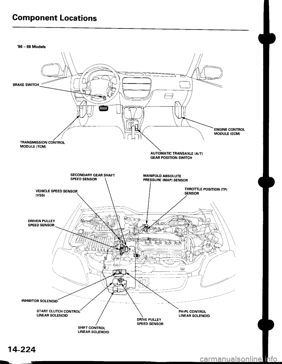
Component Locations
36 - 98 Models
BRAKE SWITCH
DRIVEN PULLEYSPEED SENSOR
INHIBITOR SOLENOID
ENGINE CONTROLMODULE IECMI
SECONDARY GEAR SHAFTSPEEO SENSOR
AUTOMATIC TRANSAXLE (A/T}GEAR POSITION SWITCI{
MANIFOLD ABSOLUTE
VEHICLE SPEEO SENSOR{vss}
IMAPI SENSOR
THROTTI.I POSITION {TPISENSOR
PH.PL CONTROLLINEAR SOLENOID
/i/ i,' / ,','4
,i/:1
t"--.---.- i,,
-_,-:-_a.--:
il
START CLUTCH CONTROLLINEAR SOLENOIDPULLEY
SHIFT CONTROLLINEAR SOLENOTD
$r,
14-224
h
SPEED SENSOR
Page 1224 of 2189
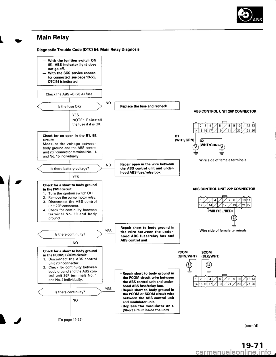
tfMain Relay
Diagnostic Trouble Code {DTC} 54: Msin Relay Diagnosis
YES
NOTE: Reinstallthe fuse if it is OK.
ABS CONTROL UNIT 26P CONNECTOR
Wire side of female terminals
ABS CONTROL UNIT 22P CONNECTOR
B1{WHT/GRNI
\e
PCOMIGRN/WHT}scoM{BLK/WHTI
(cont'd)
19-71
Wire side of female terminals
- With the ignition switch ON
{ll), ABS indic.tor light doesnot go off.- With the SCS 3ervica connoc-
tor connected (s€e pag€ 19-561,
DTC 54 is indicated.
checkthe ABS +B (20 Alfuse.
Replace th6 fuso and rechock.
Ch€ck for an op€n in the 81, 82
circuit:Measure the voltage betweenbody ground and the ABS control
unit 26P connector terminal No. '14
and No. 15 individually.
Repair open in the wire betweonthe ABS control unit and under-hood ABS tuse/relav box.
Check for a short lo body ground
in the PMR circuit:1- Turn the ignition switch OFF.
2. Remove the pump motor relay.
3. Disconnect the ABS controlunit 22P connector.4. Check for continuity betweenterminal No. 19 and bodygrouno.
Repair short to body ground in
the wire between the undor-hood ABS fuse/relay box andABS control unit.
ls there continuity?
Check tor a short to body ground
in the PCOM, SCOM circuit:1. Disconnect the ABS controlunit 26P connector.2. Check for continuity betweenbody ground and the ABS con-trol unit 26P terminals No. 1
and No.2 individually.
. Bepai. short to body ground in
tho PCOM circuit wire betwoenthe ABS control unit and under-hood ABS fu3e/.olay box.. Repair 3hort to body ground inthe PCOM or SCOM circuit wirebetween the ABS control unitand moduletor unit.. Rcplace th6 modulator unit.(Short circuit insido tho unit)
ls there continuity?
{To page 19 72)lr
Page 1502 of 2189
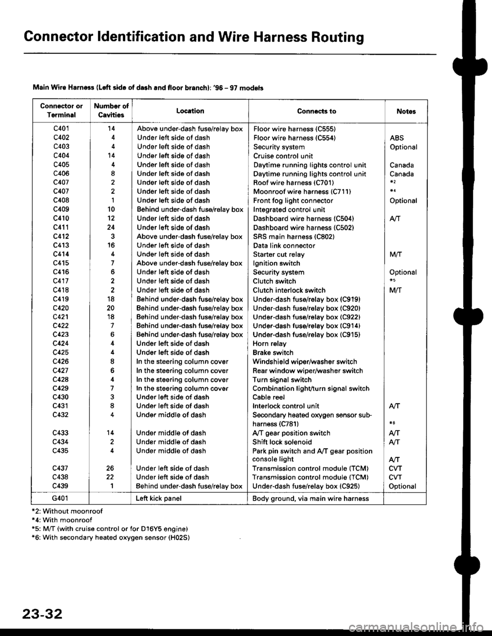
Connector ldentification and Wire Harness Routing
Connector or
Terminal
Number of
CavhiosLocationConnocts ioNotes
c401
c402
c403
c404
c405
c406
c407
c407
c408
c409
c410
c411
c412
c413
c414
c415
c416
c417
c418
c4l9
c420
c42'l
c423
c424
c425
c426
c427
c42A
c429
c430
c431
c432
c433
c434
c435
c431
c438
c439
'14
't4
I
I
10't2
24
16
7
o
18
20
18
7
6
I
o
4
7
8
14
1
Above under-dash fuss/relay box
Under left side ot dash
Under left sid€ of dash
Under left side of dash
Under left side of dash
Und€r left side of dash
Under left side of dash
Under left side of dash
Under left side of dash
Behind under-dash fuse/relay box
Under left side of dash
Under left side of dash
Above under-dash fuse/relay box
Under left side of dash
Under left side of dash
Above under-dash fuse/r€lay box
Under left side of dash
Under left side of dash
Under left side of dash
Behind under-dash fuse/relay box
Eehind under-dash fuse/relay box
Behind under-dash fuse/relay box
Behind under-dash fuse/relay box
Behind under-dash fuse/relay box
Under left side of dash
Under left side of dash
In the steering column cover
In the steering column cover
In the steering column cover
In the steering column covEr
Under left side of dash
Under left side of dash
Under middle of dash
Under middle of dash
Under middle of dash
Under middle of dash
Under left side of dash
Under left side of dash
Eehind under-dash fus€/relay box
Floo. wire harness (C555)
Floor wire harness (C554)
Security system
Cruise control unit
Daytime running lights control unit
Daytime running lights control unit
Roof wire harness (C701)
Moonroof wire harness (C7l1)
Front fog light connector
Integrated control unit
Dashboard wire harness (C504)
Dashboard wire harness (C502)
SRS main harness (C802)
Data link connector
Starter cut relay
lgnition switch
Security system
Clutch switch
Clutch interlock switch
Under-dash fuss/relay box (C9191
Undor-dash fuse/r€lay box {C920)
Under-dash tuse/relay box (C922)
Under-dash luse/relay box (C914)
Under-dash fuse/rBlay box (C915)
Horn relay
Brake swilch
Windshield wiper/washer switch
Rear window wiper/washer switch
Turn signal switch
Combination lighvturn signal switch
Cable reel
lnterlock control unit
Secondary heated oxygen sensor sub-
harn€ss (C781)
Ay'T gear position switch
Shift lock solenoid
Park pin switch and Ay'T gear position
console light
Transmission control module (TCM)
Transmission control module {TCM)
Under-dash fuse/relay box {C925)
ABS
Optional
Canada
Canada
Optional
Atr
MTT
Optional
Mlf
NT
Atf
CVT
CVT
Optional
AN
Atr
G401Left kick panelBody ground, via main wire harness
Main Wir€ Harness (Loft side of da3h and floor branch): '96 - 97 models
*2:Without moonroof*4: With moonroof*5: M/T (with cruise control or for D16Y5 engine)*6: With secondary heated oxygen sensor (H02S)
23-32