1997 HONDA CIVIC Control Module AT
[x] Cancel search: Control Module ATPage 1980 of 2189
Gauges (cont'd)
- How the Gircuit Works
When the ignition switch is in ON (ll) or START (lll),
battery voltage is supplied through fuse 25 to the
gauges in the gauge assembly.
Speedometer and Odometer
The odometer and soeedometer drive circuits
receive pulses from the vehicle speed sensor
(VSS). The pulse rate increases as the car
accelerates. The frequency and duration of these
input pulses are measured and displayed by the
speedometer, odometer and tripmeter.
Tachometer
The tachometer drive circuit receives pulses from
the ignition control module (lCM) in the distributor
assembly or the ECM/PCM. The solid-state
lachometer then displays these pulses as engine
speed. For each 200 pulses per minute from the
ignition control modul€ (lCM) or the ECM/PCM, the
tachometer displays 100 RPM.
Engine Coolant Temperature Gauge
The engine coolant temperature gauge has two
intersecting coils wound around a permanent
magnet rotor. Voltage applied to the coils, through
fuse 25, generates a magnetic lield. The magnetic
field, controlled by the coolant temperature sending
unit, causes the rotor to rotate and the gauge
needle to move. As the resistance in the sending
unit varies, current through the gauge coils
changes. The gauge needle moves toward the coil
with the strongest magnetic field.
The 6ngine coolant temperature sending unit's
resistance varies from about 137 ohms at low
engine temperature to between 3H6 ohms at high
temperature (radiator fan running).
Refer to the Service Manual (Section 23, Electrical)
for specific tests or troubleshooting procedures.
81-2
(
Fuel Gauge (All except cX)
The fuel gauge has two intersecting coils wound
around a permanent magnet rotor. Voltage applied
to the coils, through tuse 25, generates a magnetic
field. The magnetic field, controlled by the fuel
gauge sending unit, causes the rotor to rotate and
the gauge needle to move. As the resislance in the
sending unit varies, current through the gauge coils
changes. The gauge needle moves toward the coil
with the strongest magnetic field.
The fuel gauge sending unit's resistance varies
from about 2-5 ohms at full, to about 110 ohms at
empty. When you turn the ignition switch off, the
gauge remains at the last reading until you turn the
ignition switch to ON (ll) or START (lll) again,
Refer to the Service Manual (Section 23, Electrical)
for specific tests or troubleshooting procedures.
Fuel Gauge (GX)
The fuel gauge has two intersecting coils wound
around a permanent magnet rotor. Voltage applied
to the coils, through fuse 25, generates a magnetic
field. The magnetic field, controlled by the PCM,
causes the rotor to rotate and the gauge needle to
move. The PCM calculates the gas quantity in the
fuel tank by using the fuel pressure value detected
by the tuel tank pressure sensor and the fuel
temperature value detected by the fuel tank
temperalure sensor, and outputs the signal to the
gauge assembly. The gauge needle moves toward
the coil with the strongest magnetic field.
When you turn the ignition switch off , the gauge
remains at the last reading until you turn the ignition
switch to ON (ll) or START (lll) again. When the
PCM detects a malfunction with the fuel pressure or
temperature, or detects a gas leak, the PCM
reduces the fuel meter to 0.
Refer to the Service Manual GX Supplement
(Section 11 , Fuel and Emissions) for specific tests
or troubleshooting procedures.
a
a
Page 1983 of 2189
A/T Gear Position Indicator (conrd)
- How the Circuit Works
With the ignition switch in ON (ll) or START (lll),
voltage is applied to the A,/T gear position indicator.
The A,/T gear position switch provides a ground for
each position. As an input is grounded, its indicator
light comes on. lf you select R, for example, ground
will be provided to the input of the A,/T gear position
indicato( and the R indicator will come on.
With the headlight switch in PARK or HEAD, voltage
is applied to the RED/BLK wire terminal. This
changes the indicator panel illumination from fixed
to controlled by the dash lights dimmer input
through the RED wire.
When the powertrain (all except '96-'98 CVT) or
transmission ('96198 CVT) control module (PCM or
TCM) detects an abnormality in the automatic
transmission control system, or when you request
diagnostic trouble codes through the service check
connector, the PCM or TCM will make the D4 (D for
CVT) indicator light blink.
Refer to the Service Manual (Section 14,
Automatic Transmission) for specific tests or
troubleshooting procedures.
\ia
89-2
Page 2101 of 2189

Gomponent Location
121. Behind Left Kick Panel ('96-'98 CVT)\124. Rear of Engine Compartment (CVT)
TRANSMISSIONCONTROL MODULE(rcM)
122. Right Side Lower Engine Compartment (CVT)125. Behind Right Side of Dash Panel
\
123. Right Front of Engine (CVT)126. Underside of Hatch Lid
k
2A1-20
\
Page 2108 of 2189
-
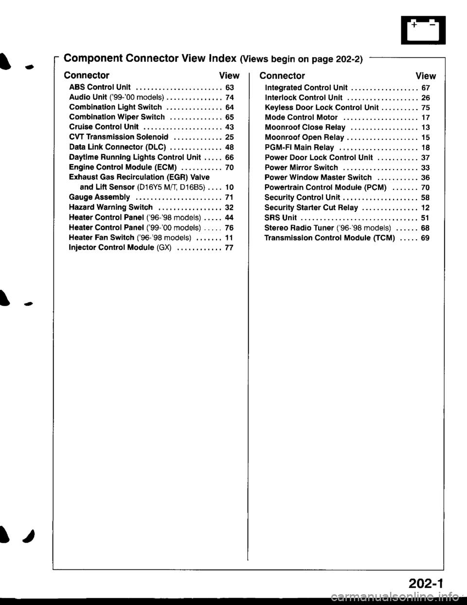
Component Connector View Index (Views begin on page 202-21
Connector View
ABS Control Unit........ ......63
Audio Unit ('99-'00 models) ......74
Combination Light Switch . . . . . . . . . . . . . . . 64
Combination Wiper Switch . . . . . . . . . . . . . . 65
Cruise Control Unit.... .....43
C\TTTransmission Solenoid ............. 25
Data Link Connector (DLC) ..... 48
Daytime Runnlng Lights Control Unit ..... 66
Engine control Module (ECM) ...........70
Exhaust Gas Recirculation (EGR) Valve
and Lift Sensor (D16Y5 Mfl, D1685) . . . . 10
Gauge Assembly .............71
HazardWarnlngSwitch,,. .,,,...,,,,... 32
Heater Control Panel ('96-'98 models) .....44
Heater Control Panel ('99-'00 models) ...., 76
Heater Fan Switch ('96-'98 models) ,,,.... 11
fniector Control Module (GX) ............77
I/
202-1
Connector View
Integrated Control Unit .......,. 67
f nterfock Control Unit .... ...... 26
Keyfess Door Lock Control Unit . . . . , . . . . . 75
Mode Control Motor ... ........'17
Moonroof Close Relay .. .......13
Moonroof Open Relay ... .......15
PGM-FI Main Relay .. .......... 18
Power Door Lock Conlrol Unil ..... ...... 37
Power Mirror Switch .,... ...... 33
Power Window Master Switch .,.........36
Powertrain Control Module (PCM) .......70
Security Control Unit ..., ..,,... 58
Security Starter Cut Belay ... ...,,,....,, 12
SRS Unit ............. 51
Stereo Radio Tuner ('96-'98 models) ...... 68
Transmission Control Module CICM) .....69
Page 2132 of 2189
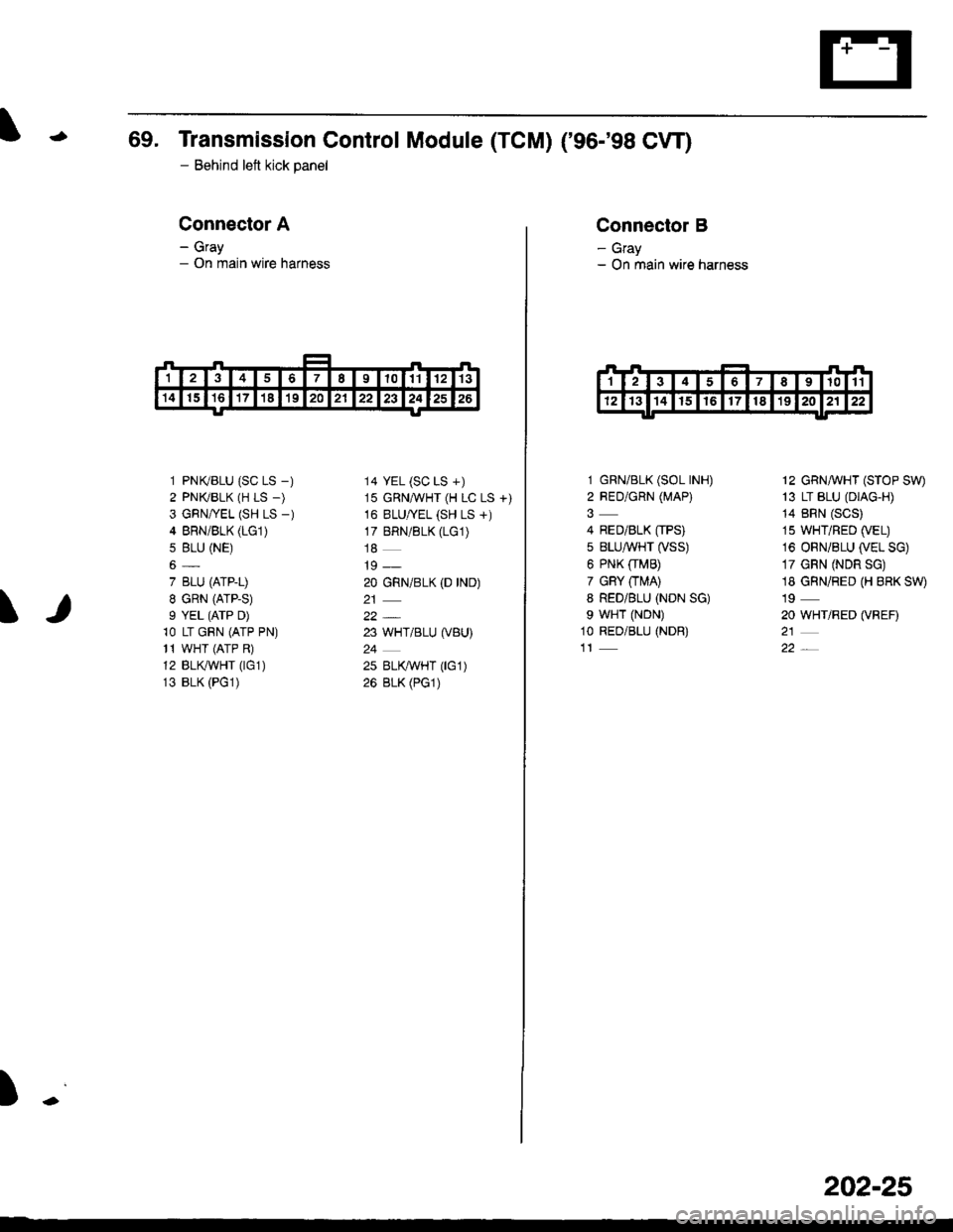
-69. Transmission Control Module (TCM) ('96-'98 CVT)
- Behind left kick panel
Connector A
- Gray- On main wire harness
\
1 PNI(BLU (SC LS -)
2 PN|(BLK (H LS -)
3 GRN/YEL (SH LS _)
4 BRN/BrK (LG1)
5 BLU (NE)
6-
7 BLU (ATP-L)
I GRN (ATP-S)
9 YEL (ATP D)
1O LT GRN (ATP PN)
11 WHT (ATP R)
12 BL(WHr (rG1)
13 BLK (PG1)
14 YEL (SC LS +)
15 GRNMHI (H LC LS +)
16 BLU/YEL (SH LS +)
17 BRN/BLK (LG1)
18
19 _
20 GRN/BLK (D IND)
23 WHT/BLU ryBU)24
2s BLI(WHT (rG1)
26 BLK (PG1)
)
Connector B
- Gray- On main wire harness
1 GRN/BLK (SOL rNH)
2 RED/GRN (MAP)
4 RED/BLK |rPS)5 BLUMHT (VSS)
6 PNK [rMB)7 GRY rrMA)8 RED/BLU (NDN SG)
9 WHT (NDN)
1O RED/BLU (NDR)
12 GRNAVHT (STOP SVV)
13 LT BLU (DIAG-H)
14 BRN (SCS)
15 WHT/RED (VEL)
16 ORN/BLU (vEr SG)
17 GRN (NDR SG)
18 GRN/RED (H BRK SW)
19
20 WHT/RED (VREF)
202-25
Page 2140 of 2189
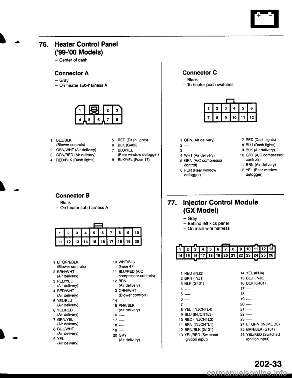
76. Heater Control Panel
('99100 Models)
- Center of dash
Conneclor A
- Gray- On heater sub-harness A
BLUi BLK(Blower controls)
GRNAVHT (Air delivery)
GRN/RED (Air delivery)
RED/BLK (Dash lights)
Connector B
- Black- On heater sub-harness A
7
8
1
4
RED (Dash lights)
BLK (G402)
BLUfYEL(Rear window defogg€0
BLK,TYEL (Fuse 17)
\
)
1 LT GRN/BLK(Blower controls)
2 BRN,A/VHT(Air delivery)
(Air delivery)
4 REDA/VHT(Air delivery)
5 YEUBLU(Air delivery)
6 YEURED(Air delivery)
7 GRN/YEL(Air delivery)
8 BLU,ryVHT(Air delivery)
9 YEL
{Air delivery)
1O WHT/BLU(Fuse 47)
11 BLU/RED WCcompressor controls)
12 BRN(Air delivery)
13 ORNAVHT(Blower controls)
14 -
15 PN(BLK(Air delivery)
16 _
19 _
20 GRY(Air delivery)
Connector C
- Black- To heater push switches
1 ORN (Air delivery)
2
4 WHT (Air delivery)
5 GRN (ry'C compressorcontrol)
6 PUR (Roar windowdelogge4
7 RED (Dash lights)
8 BLU (Dash lights)
I BLK (Air delivery)
10 GRY (Ay'C compressorcontrols)
1'1 BRN (Air delivery)
12 YEL (Rear window
defogge0
77. Injector control Module
(GX Model)
- Gray- Behind left kick panel- On main wire harness
1 RED (rNJ2)
2 BRN (rNJl )3 BLK (G401)
4_
8 YEL (TNJCNTL4)
9 BLU (TNJCNTL3)
1o RED (tNJCNTL2)
11 BRN 0NJCNTL1)12 BRN/BLK (G101)
13 YEURED (Switched
ignition input)
14 YEL (tNJ4)
15 BLU (rNJ3)
16 BLK (G401)
19 -
20-
21
24 LI GRN (INJMODE)
25 BRN/BLK (Gr 01)
26 YEURED (Switched
ignition input)
202-33
Page 2163 of 2189
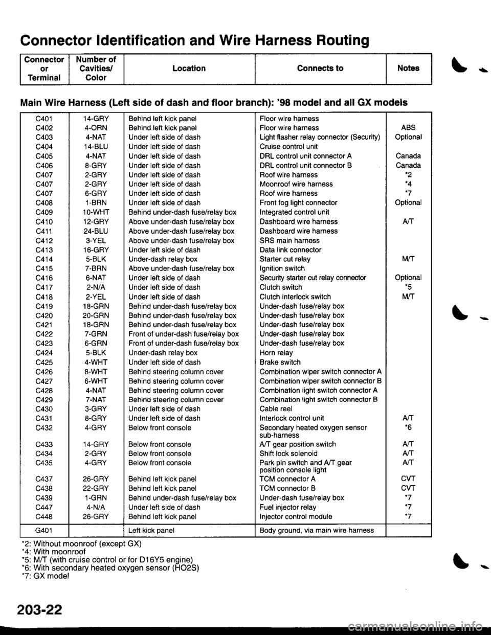
Connector ldentification and Wire Harness Routing
Connector
or
Terminal
Number of
Cavities/
Color
LocationConnects toNotess
Main Wire Harness (Left side of dash and tloor branch): '98 model and all GX models
c401
c402
c403
c404
c405
c406
Q407
c407
c407
c408
c409
c410
c411
c412
c413
c414
c415
c416
c417
c418
c419
c420
c421
c422
c423
c424
c425
c426
c427
c428
c429
c430
c431
c432
c433
c434
c435
c437
c438
c439
c447
c448
14-GRY
4.ORN
4-NAT
14-BLU
4-NAT
8.GRY
2.GRY
2-GRY
6.GRY
1-BRN
1O-WHT
12-GRY
24-BLU
3-YEL
16-GRY
5-BLK
7-BRN
6-NAT
2.N/A
2.YEL
18.GRN
2O.GRN
18-GRN
7.GRN
6.GRN
5-BLK
4.WHT
8-WHT
6-WHT
4-NAT
7-NAT
3.GRY
8-GRY
4-GRY
14-GRY
2.GRY
4.GRY
26.GRY
22-GRY
1.GRN
4-N/A
26-GRY
Behind lett kick panel
Behind lett kick panel
Under lett side of dash
Under lett side ol dash
Under lett side of dash
Under left side of dash
Under lett side of dash
Under lett side ot dash
Under left side of dash
Under l€ft side of dash
Behind undsr-dash tuse/rBlay box
Above under-dash tuse/relay box
Above under-dash tuse/relay box
Above under-dash fuse/relay box
Under lett side of dash
Under-dash relay box
Above under-dash tuse/relay box
Under left side of dash
Under lett side of dash
Under left side of dash
Behind under-dash tuse/relay box
Behind under-dash tuse/relay box
Behind under-dash tuse/relay box
Front of under-dash tuse/relay box
Front ol under-dash fuss/relay box
Under-dash relay box
Under lett side ot dash
Behind steering column cover
Behind steering column cover
Behind steering column cover
Behind steering column cover
Und€r left side of dash
Under lett side of dash
Below front console
Below front console
Below front console
Below front console
Behind left kick panel
Behind left kick panel
Behind under-dash fuse/relay box
Under lett side of dash
Behind left kick panel
Floor wire harness
Floor wire harness
Light tlasher relay connector (Security)
Cruise control unit
DRL control unit connector A
DRL control unit connector B
Boot wire harnsss
Moonroof wire harness
Boof wire harness
Front fog light connector
Integrated control unit
Dashboard wire harness
Dashboard wire harness
SRS main harness
Data link connector
Starler cut rslay
lgnition switch
Security strarter cut relay connector
Clutch switch
Clutch interlock switch
Under-dash fuse/relay box
Under-dash fuse/relay box
Under-dash fuso/rolay box
UndeFdash fuse/relay box
Under-dash fuse/relay box
Horn relay
Brake switch
Combination wiper switch connector A
Combinalion wiper srvitch connector B
Combinalion light switch connector A
Combinalion lighi swilch connector B
Cable reel
lnterlock control unil
Secondary heated oxygen sensorsuD-narness
A,/T gear position switch
Shift lock solenoid
Park pin switch and A/T gearposition console light
TCM connector A
TCM connector B
Underdash lus€/relay box
Fuel injector relay
Injector control module
ABS
Optional
Canada
Canada,2
,4
'7
Optional
AIf
Mtf
Oplional'5
M/T
AN'6
An
A,/T
Alf
CW
CVT'7
'7
'7
G401Left kick panelBody ground, via main wire harness
-2: Without moonroof (except GX)-4: With moonroof'5: M/T (with cruise control or for D16Y5 engine)'6: With secondary heated oxygen sensor (H02S)t7: GX model
203-22