1997 HONDA CIVIC For
[x] Cancel search: ForPage 661 of 2189

Synchro Ring, Gear
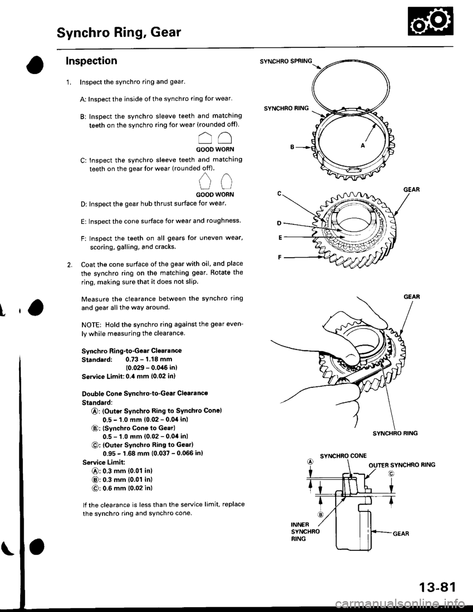
Inspection
'1. Inspect the synchro ring and gear.
A: Inspect the inside of the synchro ring for wear'
B: Inspect the synchro sleeve teeth and matching
teeth on the synchro ring for wear (rounded off).
oo
GOOD WORN
C: Inspect the synchro sleeve teeth and matching
teeth on the gear for wear (rounded off).
nn
UUGOOO WORN
D: Inspect the gear hub thrust surface for wear.
E: Inspect the cone surface for wear and roughness.
F: Inspect the teeth on all gears for uneven wear,
scoring, galling, and cracks'
2. Coat the cone surface of the gear with oil, and place
the synchro ring on the matching gear. Rotate the
ring, making sure that it does not slip
Measure the clearance between the synchro ring
and gear allthe way around.
NOTE: Hold the synchro ring against the gear even-
ly while measuring the clearance.
Synchro Ring-to-Gear Clearance
Standard: 0.73 - 1.18 mm
(0.029 - 0.0'16 in)
Ssrvice Limit:0.,0 mm {0.02 in}
Double Cone Synchro-to-Geal Clearanc€
Standald:
@: (Outer Synchro Ring to Synchro Con6l
0.5 - 1.0 mm 10.02 - 0.04 in)
@: (Synchro cone to Gearl
0.5 - 1.0 mm (0.02 - 0.04 inl
O: {Outer Synchlo Ring to Gear)
0.95 - 1.68 mm (0.037 - 0.066 in)
Service Limit:
@: 0.3 mm {0.01 in}
@: 0.3 mm {0.01 in)
O: 0.6 mm t0'02 inl
lf the clearance is less than the service limit, replace
the synchro ring and sYnchro cone.
SYNCHRO SPRING
SYNCHRO RING
t
SYNCHRO CONE
13-81
Page 663 of 2189

rla
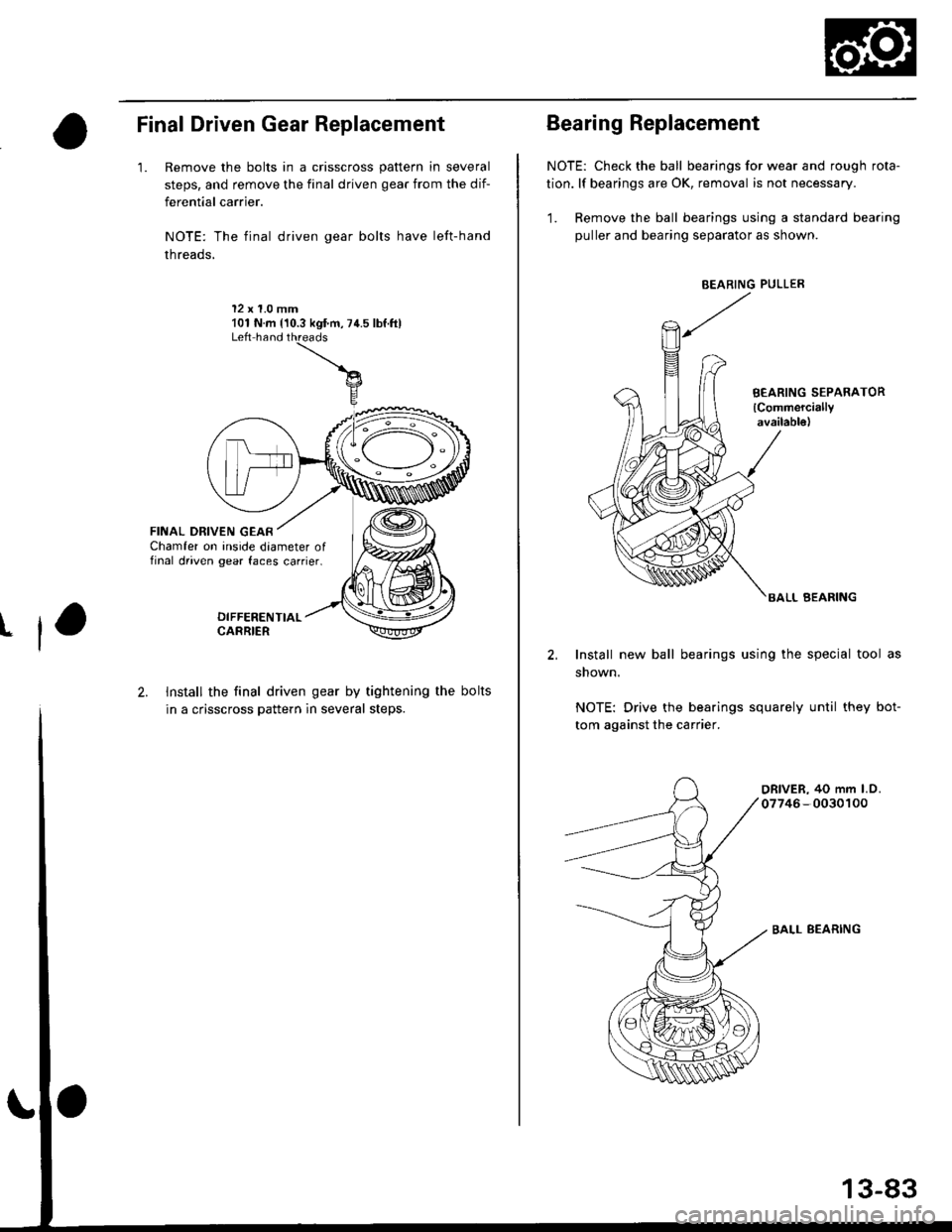
Final Driven Gear Replacement
'1. Remove the bolts in a crisscross pattern in several
steps, and remove the final driven gear from the dif-
ferential carrier.
NOTE: The final driven gear bolts have left-hand
threads,
12 x 1.0 mm101 N.m {'10.3 kgf.m,74.5 lbf.ftlLeft hand
FINAL DRIVEN GEARChamfer on inside daameter offinal driven gear faces carrier.
2. Install the final driven gear by tightening the bolts
in a crisscross pattern in several steps.NOTE: Drive the bearings squarely until they bot-
tom against the carrier.
BALL BEARING
13-83
Bearing Replacement
NOTE: Check the ball bearings for wear and rough rota-
tion. lf bearings are OK, removal is not necessary.
1. Remove the ball bearings using a standard bearing
puller and bearing separator as shown.
BEARING PULLER
BEARING SEPARATOR
lCommerciallyavailab16)
BALL BEARING
2. Install new ball bearings using the special tool as
shown.
Page 668 of 2189

Mainshaft Thrust Clearance
Adjustment
1. Remove the 72 mm thrust shim and oil guide platefrom the transmission housing.
4.
TFANSMISSIONHOUSING
72 mm THRUST SH|M
TRAt{SMtSStONHOUSINGOIL GUIOE PLATE
lnstall the 3rd/4th synchro hub. spacer collar,5thsynchro hub. spacer, and ball bearing on the main_shaft, then install the above assembly in the trans_mission housing.
lnstall the washe[ on the mainshaft,
Measure distance @ between the end of the trans-mission housing and washer.
NOTE;
. Use a straight edge and vernier caliper.. Measure at three locations and average the read_ing.ENO otlnA sMtsstoNHOUSINGMAINSHAFT
3RD/irTH SYNCHRO HUB
SPACCR COLLAR
5TH SYNCHRO HUB
o
B
13-88
AALL BEARING
V.
5. Measure distance @ between the end of the clutchhousing and bearing inner race.
NOTE;
. Use a straight edge and depth gauge.. Measure at three locations and average the read-ings.
Select the prcpet 72 mm thrust shim from the chartby using the formula below.
NOTE: Us€ only one 72 mm thrust sntm.
Shim Selection Formula:
From the measurements you made in steps 4 and 5:. Add distance O lstep 5) to distance @ (step 4).
. From this number, subtract 0.93 (which is themidpoint of the flex range of the clutch housingbearing spring washer).
. Take this number and compare it to the availableshim sizes in the chart.
{For example)
B;2.39
+ C: 0.22- 0.93
2.61 = 1.68
Try the 1.68 mm (0.0661 in) shim.
INNER RACE ot EALL BEARING
Page 669 of 2189

72 mm Thrust Shim
t
Part NumberThickness
23931 - P21 0000.60 mm {0.0236 in}
23932-P21 -0000.63 mm 10.0248 in)
c23933 P21 - 0000.66 mm (0.0260 in)
D23934 - P21 0000.69 mm (0.0272 in)
E2393s-P21-0000.72 mm (0.0283 in)
F23936-P21 -0000.75 mm (0.0295 in)
G23937 -P21-O000.78 mm (0.0307 in)
23938-P21 -0000.81 mm (0.0319 in)
23939-P21 -0000.84 mm (0.0331 in)
J23940-P21 -0000.87 mm (0.0343 in)
K23941 P21 - 0000.90 mm (0.0354 ini
L23942 - P21 0000.93 mm (0.0366 in)
23943-P21 -0000.96 mm 10.0378 in)
N23944 - P21 -0000.99 mm (0.0390 in)
o23945 - P21 0001.02 mm (0.0402 in)
P23946 - P21 0001.05 mm (0.0413 in)
o23947 - P2l 0001.08 mm (0.0425 in)
R23948-P21 -0001.'1 'l mm (0.0437 in)
S23949 - P21 0001.14 mm (0.0449 in)
T23950 - P21 0001.17 mm (0.0461 in)
23951 - P21 -0001.20 mm (0.0472 in)
23952 - P21 -0001.23 mm (0.0484 in)
23953-P21 -0001.26 mm (0.0496 in)
X23954-P21 -0001.29 mm (0.0508 in)
23955 - P21 -0001.32 mm (0.0520 in)
z23956-P21 -0001.35 mm (0.0531 in)
23957-P21 -0001.38 mm 10.0543 in)
AB23958 - P21 -0001.41 mm (0.0555 in)
AC23959 P21 - 0001.44 mm {0.0567 in)
23960 - P21 0001.47 mm (0.0579 in)
AE23961 - P21 -0001.50 mm {0.0591 in)
23962 P21 - 0001.53 mm {0.0602 in)
AG23963-P21 -0001.56 mm (0.0611in)
AH23964-P21 -0001.59 mm {0.0626 in)
23965-P21 -000'1.62 mm {0.0638 in)
23965-P21 - 0001.65 mm (0.0650 in)
AK23967-P21 -0001.68 mm {0.0661 in)
23968 - P21 -0001.71 mm 10.0673 in)
23969 P21 - 0001.74 mm {0.0685 in)
AN23970-P21 -0001.77 mm {0.0697 in)
AO23971 - P21 -0001.80 mm (0.0709 in)
7. lnstallthe thrust shim selected and oil guide plate in
the transmission housing.
72 mm THRUSTOIL GUIDE PLATE
TRANSMISSIONHOUSING
8. Install the spring washer and washer on the ball
beaflng.
NOTE:
. Clean the spring washer, washer and thrust shim
throughly before installation.
. Install the spring washer, washer and thrust
shim properlY.
-WASH€R-<]>-.-'
x -sPRtNG WASHER
-.-sK((9r'
lnstallthe mainshaft in the clutch housing.
Place the transmission housing over the mainshaft
and onto the clutch housing.
Tighten the clutch and transmission housings with
several 8 mm bolts.
NOTE: lt is not necessary to use sealing agent
between the housings.
8 x 1.25 mm
27 N.m (2.8 kgf.m. 20 lbf'ft)
Tap the mainshaft with a plastic hammer.
(cont'd)
9.
10.
'I l.
12.
13-89
Page 671 of 2189

Transmission
ReassemblY
1. Install the new oil seal
2. Set the change Piece.
3. Install the shift rod
4. Install the steel ball' the spring, and the set screw'
5. Install the spring washer and change piece attach-
ing bolt.
6. Install the shift rod boots.
8x1.0mm31 N.m 13.1 kg-m,22lb-ltl
CHANGEPIECE
@:4OIL SEALReplace.SPRINGWASHER
7. Install the oil chamber Plate'
6 x '1.0 mm12 N.m (1.2 kg-m,9lb-ft|
SPRING
, /L.256fim B()(
@ / t't o'ti"l I
{zw"y-6@
q
10.
Set the spring washer and the washer'
lnstall the mainshaft, the countershaft, and the shift
fork assemblies.
NOTE: Align the finger of the interlock with the
groove in the shift fork shaft.
SHIFT FORKS
13-91
Page 673 of 2189

tl
15. Install the reverse change holder.
6x1.0mm'15 N.m 11.5 kgim, 11 lblftl
Instsll the oil guide plate and the 72 mm thrust shim
into the transmission housing.
17.
18.
Install the oil gutter plate.
Bend the hook of the oil gutter plate, then install the
16 mm sealing bolt.
NOTE: Apply liquid gasket {P/N 08718 - 0001 or
08718 - 0003) to the threads.
16 mm SEALING BOLT29 N.m t3.0 kgl'm, 22 lbt'ft}
Apply liquid gasket to the surface of the transmis-
sion housing as shown'
NOTE:
. Use liquid gasket (P/N 087'18 - 0001 or
08718 - 00031.
. Remove the dirty oilfrom the sealing surface'
. lf 5 minut€s have passed after applying liquid
gasket, reapply it and assemble the housings'
. Allow it to cure at least 20 minutes after assem-
blv bsfore fitling the transmission with oil'
19.
(cont'd)
13-93
--- Liqui.l gask€t
Page 677 of 2189

Gearshift Mechanism
Overhaul
NOTE:
. Inspect rubber parts for wear and damage when disassembling;
. Install the spring pin and the clip on the change joint as shown'
. Turn the shift rod boot so the hole is facing down as shown'
. Make sure the shift rod boot is installed on the shift rod'
reDlace any worn or damaged Parts.
I x 1.25 mm22 N.m 12.2 kgf.m, 16 lbf.ft)
ffi-:t't:il1ii51i?"'*,
TU
/g3i'51!Exii
V ExrENsroN
EXTENSfON ilr'eol.T
EXTENSION ENDBUSHING
hV\
EXTENSIONWASI{ER B
MOUNT -_.--_-_---
@2'
--1'>=2 -:liT.i'ff"
.o,-.o*&--ffi{---*,
v/,,/ BALL SEAT
8 x 1.25 mm22 N.m 12.2 kgf'm, 16lblftl
,@
EXTENSION ROD
SHIFT ROD
SPRING
END
BOOT
N: g sHrFr LEvER
.*rr"r,o"-tf V-oiliiSi[a
MOUNTING I --::=t SHIFT I"EVERBRAcxEr / €9-l--enr xoloen
8 x 1.2s mm :-,rro""a,ii-ri- ri.z rsr.-, -.Q u
16 tbf.ft) ,,,.
,rar-aoa*,"o "u, / E ,",t.ruaa
Replace.6x1.0mm9.8 N.m ('1.0 kgt'm,7 tbr.ftt
8x22mmSPRING PINReplace.
IIt
@CLIP
9.a-"t't
PIN SHIFT ROD/
ZW
€lt#-,\
HOLE
13-97
Page 679 of 2189

Automatic Transmission
Special Tools ......... .....'."".'-.-.' 14'2
Description .,....................-...... 14-3
power Flow ......,................. 14"6
Elestronic Control System .... . ................'..'.'.. 14-13
Hvdraulic Control .....'......" 1'l-19
Hydraulic F|ow...... .'.'.".'....11-21
Lock-up System '............ ... t/t'33
Electrical System
Component Locations....,.............'......'.............'.,. 14'39
PCM Circuit Diagram
lA/T Control Syst€m: '96 - 98 Models) .........'.. 1/t-40
PCM Tarminal Volt8ge/Measuring Condhions
{'96 - 98 ModeblA/T Control System ............
PCM Circuit Disgram(A/T Conlrol System: '99 - 00 Modsls) '..........' 14-44
PCM Terminal Voltage/Measuring Conditions('99 - 00 Models)A/T Control System ...
Troubleshooting Proceduros ....
Symptom-to-ComPonent Chari
Efectricaf SFiem - '96 - 98 Models '..-.-..."'.'..11-52
Eloqtrical System -'99 - 00 Modols ... .........". 1+54
EleclricatTroubl$hooting ('96 - 98 Models)
Valve Body
Repair .................... ........'.... 14-139
Valve
Assembly
ATF Pump
1,1-1i10
Inspection ...........'.......... 14-141
Main Valvs Body
Disass€mbf y/lnspoction/R.sssembly .'.'.'.'.. -. -. 1 1-1 12
Secondsry Valve BodY
Disa$embfy/lnspoction/Rsassembly ......'.'.'.'. 11-111
Regulator Valve Body
Disa$embly/lnspoction/Rea3sembly ..........'... 14-1{5
Servo Body
Disassombly/lnsp€ction/Reassembly .".'........ 14-146
Lock-up Valv6 Body
Dis$s.mbf y/ln3poction/Rea$embly .'.. -. -..'.'.' 1 1-1 17
Mainsh!ft
Dkassembly/lnep€ction Reassembly ..'...'........ 14'148
Inspoction .............'..........'. l it-149
Countsrshaft
Disa$embly/lnspeqtion/Rea3sembly .......'...'.. 1a-l51
Dba$ombly/Re$s.mblY11-152
til-46
I rl-48
Troubleshooting Flowcharts
Electrical Troubleshooting ('9!t - 00 Models)
Troublsshooting Flowchart3
Lock-up Control Solenoid vslvo A/B AssemblY
RePlacoment
Shift Cont.ol Solenoid Valve A/B A3sembly
Inspestion
Ona-way Clutch
Disassembh/lrupoction/Rca$embly .. "'........ l4-155
Clutch
lllustlttcd Ind.x {A48A, B4RA Transmlssion) ..' 14-156
tustr.tod Index (MrnA Transmi$ionl ............ til-158
...................... 14-153
L
14-56
1+81'
14-105
1+105
Replacoment ......
Mainshaft/Countorshaft Spo€d Sonsors
Replacemsnt ......'."'........... lit'108
Hydraulic System
Symptom-to-Componeni Chart
Hydraulic Sydemr+109
t4-113
1+116
11-117
Rea$emblY
14-106 Difforrr ial
llhdraied Index........ t4-156
B.ckhrh ln3poction. 14-167
Boaring Roplacemont..-..........11-167
..... 14-108 Diftrrsniial Carrior Repl8cemeni .'.-.............'...' lil-168
Oil Sall Romovalt4-t 59
Oil Soal ln3tallstion/Sidc Clearance'......'.....'... 1'l'169
Torqua Convertcr Housing Boarings
Mlin3haft Besring/Oil Scal Roplac.ment ."..'.. lil-172
Counio6hatt Betring R.plscem.nt ..'...... ....... 14-173
Test.....,......14-106
14-107
14-160
11-162
11-171
11-175
Replacement
Test .....,.,..........
Road Te3t
Linear Solenoid AsssmblY
Stall Speed
lllustrated Indax
Transmission/End Cover'. ....
Transmission Hou3ing,.............'.'......'....""..-.-.. 11-128
Torque Conve.ter Housing/Valvo Body ........... 14-130
End Cover
14-itB Park Stop
1+119 In3pection/Adiustmsnt...'......'.'............'...."""'14-175
Transmbgion
Reassombly
11-122 Torquo Convertet/Drivr Plsie ............'.'............'.. . l4-182
Transmission
11.726 Inrtallation
Tranlmission Housing Boarings
Msinsh.ft /CounteEhaft Bearings
B!pltcomgnt
Rcvo.3s ldlor Gear
lnrtallation
Cooler Flushing ..
Shift Cabls
Test
Fluid Level
Checkin9 .........."..'.'.....
Changing
Pressure Testing
Transmission
Transmission
Rgmoval ..
lil-176
.'..........'.'.'..... 1'l-183
.... lil-187
11-132Adiustmont
RemovaUlnttallation1,1-190
lit-191Transmisgion Housing
Removal ... '.'...... ......'..... 14-l3il
Tolque Convgrter Housing/valvs Body
Rsmoval .........,...... ............. 14-136
Valve CaDs
Description .......'................. t 4'138
Shift lndicator Panel
Adiu3tmant ..'.................. 14-192
ATF Coolor Hoses
Connection ..,............,.,....... l'l-192
Shift Lever .,........