Page 646 of 2189

Shift Fork Assembly
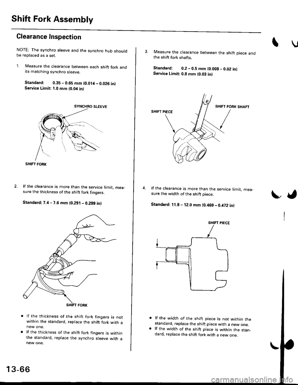
Clearance Inspection
NOTE: The synchro sleeve and the synchro hub shouldbe replaced as a set.
1. Measure the clearance between each shift fork andits matching synchro sleeve.
Standard: 0.35 - 0.65 mm {O.Olit - 0.026 inlService Limit: 1.0 mm t0.04 inl
SHIFT FOBK
lf the clearance is more than the service limit. mea_sure the thickness of the shitt fork finoers.
Standard: 7.4 - 7.6 mm (0.291 - 0.299 in)
lf the thickness of the shift fork frngers rs notwithin the standard, replace the shift fork with anew one.
lf the thickness of the shift fork fingers is withinthe standard, replace the synchro sleeve with a
13-66
3. Measure the clearance between the shift piece andthe shift fork shafts.
Standard: 0.2 - 0.5 mm (0.008 - 0.02 inlService Limit: 0.8 mm {0.03 in)
lf the clearance is more than the service limit. mea-sure the width of the shift Diece.
Standard: 11.9 - 12.0 mm (0.469 - 0.it72 in)
lf the width of the shift piece is not within thestandard, replace the shift piece with a new one.lf the width of the shift piece is within the stan_dard, replace the shift fork with a new one.
t,
SHIFT PIECE
Page 647 of 2189
Mainshaft AssemblY
lndex
Note the follow
. The 3rd/4th and the 5th synchro hubs are installed with a press
. Install the angular ballbearing with the thin-edged cuter race facing the stop rrng'
Priorto reassembling. clean all the parts in solvent,drythem, and apply lu brica nt to any contact su rfaces The
3rd/4th and the sth synchro hubs, however, should be installed with a press before lubricating them'
ANGULAR BALL BEARING
Inspect lor wear
and operation.Note the drrectlonoI installatton.
v
SYNCHROSPRING
3RO/4TH SYNCHRO HUB
3RD GEARInspection,page 13-68,81
3RO/4TH SYNCHRO SLEEVE
SYNCHROSPRING
STOP RING
TAPER RING
NEEOLE EEARINGInspect for wearand operation.
SPACER
SYNCHRO RINGInspection.page 13-81
SYNCHROSPRING
SYNCHRO HUB
5TH/REVERSESYNCHRO SLE€VE
SYNCHEOSPRING
Inspection,page 13-81
NEEDLE BEARING
and operation.
SYNCHRO RINGInspection,page 13 8'1
GEARInspeclron,page 13-70,81
NEEDLE BEARINGInspect Ior wear
and operation.COLLAB
4TH GEARInspection,page 13'69,81
13-67
Page 652 of 2189
Mainshaft Assembly
Inspection
1. Inspect the gear surfaces and the bearing surfaces
for wear and damage. then measure the mainshaft
at points A, B, and C. lf any parts of the mainshaft
are less than the service limit, reDlace mainshaft
with a new one.
Standard:
A: 27.987 - 28.000 mm {1.1018 - 1.1024 in}
B: 37.98i1 - 38.fi)0 mm (1.,|!t5,0 - 1.4960 inl
Ci27.977 - 27.990 mm 11.1015 - 1.1020 inl
Service Limit:
A; 27.940 mm {1.1000 in}
B: 37.930 mm (1./{133 in)
C:27.930 mm (1.0996 inl
(
2. Inspect for runout. lf the runout is more than the
service limit, replace the mainshaft with a new one,
Standard: 0.02 mm 10.0008 inl max.
Ssrvice Limit: 0.05 mm 10.002 inl
NOTE: Suooort the mainshaft at both ends as
shown.
t
Inspect for wearano oamage.
Inspect oil passages tor clogging.
13-72
Page 653 of 2189

Reassembly
CAUTION:
. Press the 3rd/4th and the 5th synchro hubs on the
mainshaft without lubrication.
o When installing the 3rd/,lth and the sth synchro
hubs, support the mainshaft on steel blocks, and
installthe synchro hubs using a prsss.
. Install the 3rd/4th and the sth synchro hubs with a
maximum plessur€ of 19.6 kN (2,000 kg, 14,466 lbl.
NOTE: Refer to page 13-67 for reassembly sequence.
1, Support 2nd gear on steel blocks, then install the
3rd/4th synchro hub using the special tools and a
press, as snown.
NOTE:
. After installing. check the operation of the
3rd/4th synchro sleeve and hub.
. Assemble the 3rd/4th synchro hub and sleeve
together betore installing them on the mainshaft.
Closed end
3RD/4THSYNCHRO HU3DBIVER, 10 mm l.O.07746 - 00301U)
/ lrrlcHlileNr. ss .- t.o.07746 - 0030,100
l.
3RD/{THSYNCHROSLEEVE
2ND GEAR
2. Install the sth synchro hub using the special tools
and a press as snown.
DRIVER, {0 mm l.O.07746 - 0030100
ATTACHMENT,35 mm LD.
sTH SYNCHRO HUB
07716 - 0030,100
3. Install the angular ball bearing using the special
tools and a press as shown.
PRESS
+
DRIVER, 40 mm LD.0?7a6 - It030100
Page 654 of 2189
Gountershaft Assembly
Index
DAMPER
ST GEARInspection, page 13-75
EALL EEARING
and operation.
NEEDLE BEARINGlnspect for wearano operaton.
5TH GEAR
4TH GEAR
3RD GEAR
NOTE:
3
The 4th and sth gears are installed with a press.
Prior to reassembling, clean all the parts in solvent, dry them and apply lubricant to any contact surfaces. The 4thand 5th gears. however, should be installed with a press before lubricating them.
REVERSE GEAR
LOCKNUT Replace108"0-108N.m
i11.0 - 0- l1.0kgtm,180-0-80lbttr
WASHER
DISTANCECOLLAR
COUNTERSHAFTInspection, page 13-77
NEEDLE BEARING
and operatron,
Inspection, page 13-75
NEEDLE BEARING
ano operatron,
SPACER
FRICTION DAMPER
DOUBLE CONE
Inspection, page 13 81
SYNCHRO SPRING
13-74
Page 657 of 2189
t
Inspection
1. Inspect the gear surfaces and the bearing surfaces
for wear and damage, then measure the counter-
shaft at points A, B, and C. lf any parts of the coun-
tershaft are less than the service limit. reDlace coun-
torshaft with a new one.
Standard:
A: 2/t.980 - 2{.993 mm (0.9835 - 0.9&O in}
B: 35.984 - 37.000 mm {1.4561 - 1.4567 in)
G: 33.fiD - 33.015 mm {1.2992 - 1.2998 in)
Sorvicc Limit:
Ar 2/t.9't0 mm 10.9819 inl
B: 36.930 mm {1.'l5qt in}
C: 32.950 mm {1.2972 in}
Insp€ct for wear
Inspect oil passage for clogging.
13-77
2. Insoect for runout. lf the runout is more than the
service limit, reolace the countershaft with a new
one.
Strndard: 0.02 mm {0.(x)08 in) max.
Servic. Limit 0.05 mm (0.002 in)
NOTE: SuoDort th€ countershaft at both ends as
shown.
Rotate lwo complelerevotutons.
Page 658 of 2189

Gountershaft Assembly
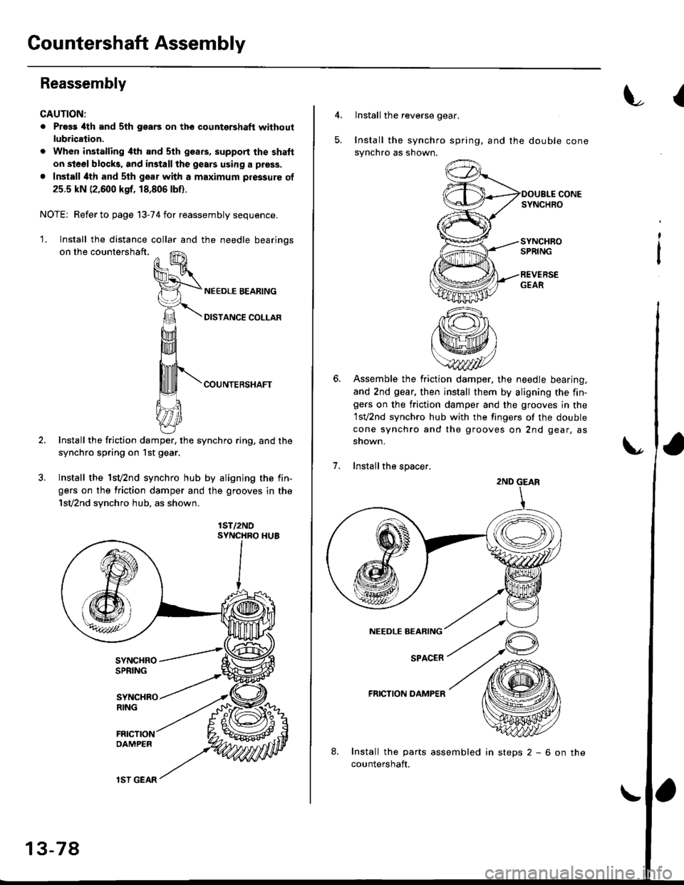
Reassembly
CAUTION:
. Pross 4th and sth gears on the countershaft without
lubrication.
. When installing ilth and sth geafs, support the shaft
on steel blocks, and install the gears using a press.
. Install ilth and sth gear with a maximum pressure of
25.5 kN (2,600 ksf, 18,806lbf).
NOTE; Refer to page 13-74 for reassembly sequence.
'1. Install the distance collar and the needle bearinos
on the countershaft.
COUNTERSHAFT
Install the friction damper, the synchro ring, and the
synchro spring on 1st gear.
Install the 1sv2nd synchro hub by aligning the fin-
gers on the friction damper and the grooves in the
1sv2nd synchro hub, as shown.
lST/2NO
13-78
lSI GEAR
insteps2-6onthe
{
4.lnstall the reverse gear.
Install the synchro spring. and the double cone
synchro as shown.
Assemble the friction damper, the needle bearing,
and 2nd gear, then install them by aligning the fin-gers on the friction damper and the grooves in the
1sv2nd synchro hub with the fingers of the double
cone synchro and the grooves on 2nd gear, as
snown.
Installthe spacer.
FRICTION DAMPER
Install the parts assembled
countershaft.
;
2ND GEAR
Page 660 of 2189
Synchro Sleeve, Synchro Hub
Inspection
1,Inspect gear teeth on all synchro hubs and synchro
sleeves for rounded off corners. which indicates
Install each synchro hub in its mating synchro
sleeve and check for freedom of movement.
NOTE: lf replacement is required, always replace
the synchro sleeve and synchro hub as a set.
Installation
When assembling the synchro sleeve and synchro hub,
be sure to match the three sets of longer teeth (120
degrees apart) on the synchro sleeve with the three sets
of deeper grooves in the synchro hub.
CAUTION: Do noi install tho synchro sleeve with its
longer toeth in the synchro hub slots, because it will
damage the spring ring.
SYNCItROSLEEVCLONGER TEETH
13-80