1997 HONDA CIVIC driver dashboard low cover
[x] Cancel search: driver dashboard low coverPage 1680 of 2189
Power Mirrors
Funstion Test (cont'dl
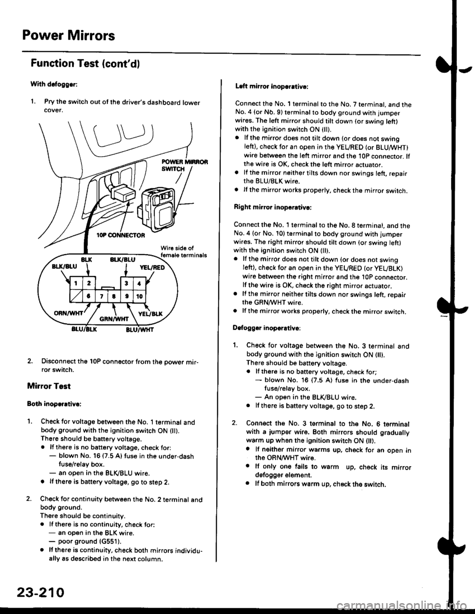
With dcfoggcr:
1. Pry the switch out ot the driver's dashboard lowercover.
2. Disconnect the 10P coonector from the oower mir-ror switch.
Mirror Test
Bolh inoparrtiv.:
1. Check for voltage between the No. 1 terminal andbody ground with the ignition switch ON flt).There should be battery voltage.. lf there is no battery voltage, check to.:- blown No. 16 (7.5 A) fuse in the under-dash
tuse/relay box.- an open in the BLVBLU wrre.
! lf thero is banery voltage, go to step 2.
2. Check for continuity b€tween the No. 2 terminal andbody ground.
There should be continuitv.. ll there is no continuity, check tor:- an open in the BLK wire.- poor ground (G5511.
. lJthere is continuity. check both mirrors individu-ally 8s described in the next column,
23-210
Laft mirror inopcrativ!:
Connect the No. 1 terminal to the No. 7 terminal. and theNo. 4 (or Nb.9) terminalto body ground with jumper
wires. The left mirror should tilt down (or swing left)with the ignition switch ON (ll).
. lf the mirror does not tilt down (o. does not swinglett), check for an open in the YEURED (or BLUMHT)wire between the left mirror and the 10p connector. lfthe wire is OK, check the left mirror actuator.a lf the mirror neither tilts down nor swings left, repairthe BLU/BLK wire.
t lf the mirror works properly, check the mirror switch.
Right mi.ror inopcrativc:
Connect the No. 1 terminal to the No. 8 terminal, and theNo.4 (or No. 10) terminalto body ground with l'umperwi.es. The right mirror should tilt down (or swing lett)with the ignition switch ON (ll).
. lf the mirror does not tilt down {or does not swingleft), check for an open in the YEURED {or YEUBLK)
wire between the right mirror and the l0P connector.lf the wire is OK, check the right mirror actuator,. lf the mirror neither tilts down nor swings left, repairthe GRN/WHT wire.o lf the mirror works properly. check the mirro. switch,
Dafoggcr inoperEtivo:
1. Check for voltage between the No. 3 terminal andbody ground with the ignition switch ON (||).
There should be battery voltage.a lf there is no battery voltage, check for;- blown No. 16 (7.5 A) luse in the under-dash
fuse/rel8y box,- An open in the BLK,iBLU wire.. It there is battery voltage, go to step 2.
2. Connsct the No. 3 tsrminal to the No. 6 terminalwith a iumpsr wire. Both mirrors should gradually
warm up when the ignition switch ON flt).a lf neither mirror warms up, check for an open inthe ORN/WHT wire.. It only on€ lails to warm up, check its mirrordsfogger elem6nt.. lf both mirrors warm up, check ths switch.
Page 1687 of 2189
Wiper/Washer Switch Test
Remove the driver's dashboard lower cover {see
section 20).
Remove the steering column covers.
Disconnect the 8P and 6P connectors from the
switch, remove the two screws, and pull out the
switch.
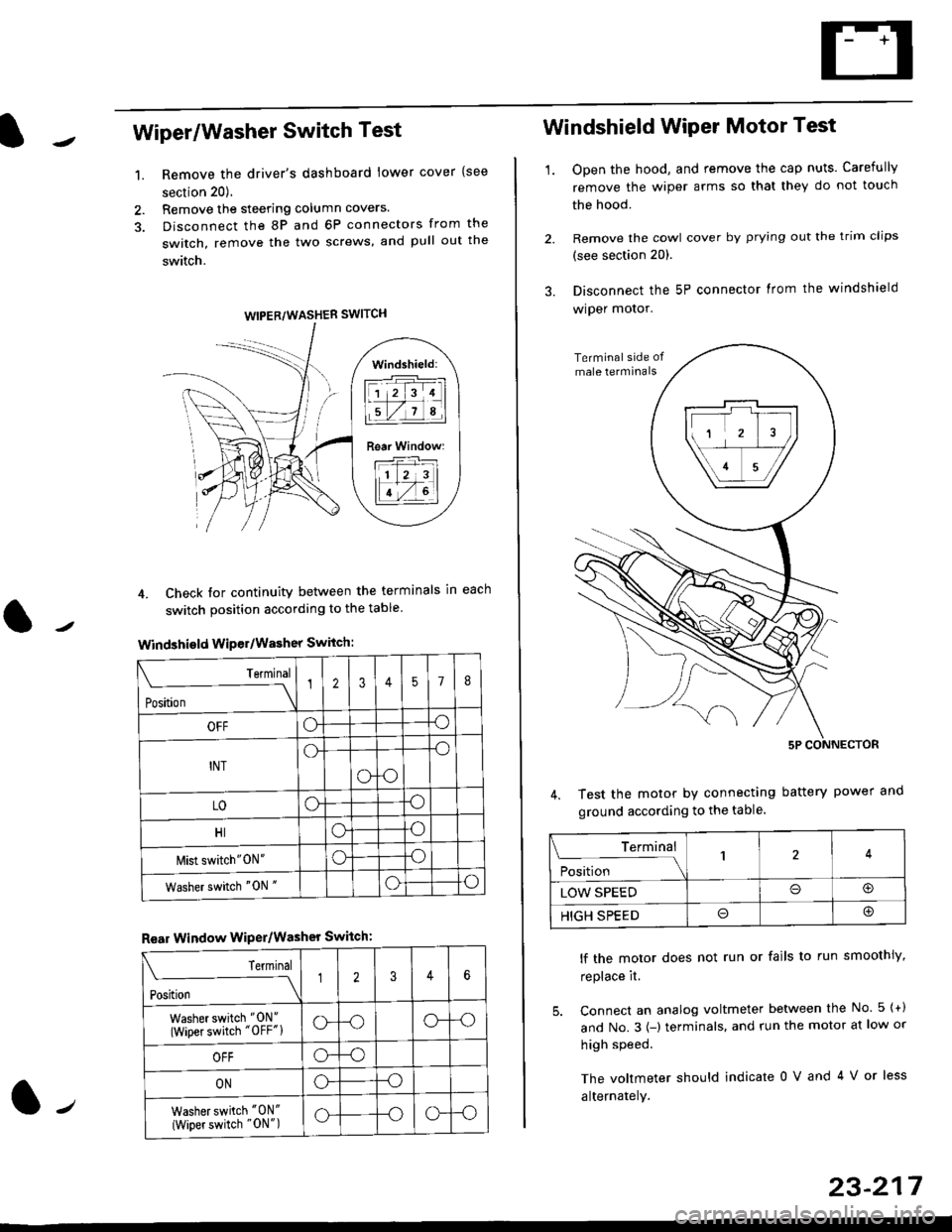
4. Check tor continuity between the terminals in each
switch position according to the table
Windshield Wiper/Washer Switch:
Terminal
Position \
12357I
OFFoo
INTo-o
oo
LOoo
HIoo
l\4ist switch"0N"oo
Washer switch "0N "oo
Rear Window WiPer/Washer Switch:
I Terminal
'i"*
--J2346
Washer switch "0N"
(Wiper switch "OFF"lo--oo--o
OFFo--o
ONo--o
Washer switch "0N"
{Wiper switch "0N")o--oo--o
1.
WIPER/WASHER SWITCH
Windshield:
l1 2 314 |
li.l7a,lil
Rear Window:
11 z 3l
lT-,rtl
Windshield Wiper Motor Test
1.Open the hood, and remove the cap nuts. Carefully
remove the wiper arms so that they do not touch
the hood.
Remove the cowl cover by prying out the trim clips
(see section 20).
Disconnect the 5P connector lrom the windshield
wiper motor.
Test the motor by connecting battery power
ground according to the table.
lf the motor does not run or fails to run smoothiy,
replace it.
5. Connect an analog voltmeter between the No. 5 {+)
and No.3 {-) terminals. and run the motor at low or
high speed.
The voltmeter should indicate 0 V and 4 V or less
alternately.
Terminal
i**l*-
-_\14
LOW SPEEDo@
HIGH SPEEDo@
23-217
Page 1707 of 2189
Funstion Test
CAUTION: Bo careful not to damago the moonroof switch
or ths driv6r's dashboard lowsr cover when prying the
3witch out.
NOTE: Check the No. 51 (20 Al fuse in the under-hood
tuse/relay box and No.24 (7.5 A) fuse in the under-dash
fuse/relay box, before testing.
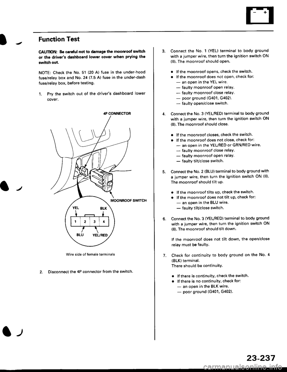
1. Prv the switch out of the driver's dashboard lower
cover.
swtTcH
Wire side of female terminals
2. Disconnect the 4P connector from the switch
4P CONNECTOR
l-t
23-237
Connect the No. 1 (YELI terminal to body ground
with a jumper wire, then turn the ignition switch ON
(ll). The moonroof should open.
. lf the moonroot opens, check the switch.
. lf the moonroot does not open, check for:
- an open in the YEL wire.
- faulty moonroof open relay.
- faulty moonroof close relay,
- poor ground (G401, G402).- fa u lty open/close switch.
Connect the No. 3 (YELnED) terminal to body ground
with a jumper wire. then turn the ignition switch ON
(ll). The moonroof should close.
. lf the moonroof closes. check the switch.
. lf the moonrool does not close, check for:
- an open in the YEURED or GRN/RED wire'
- faulty moonroof close relaY.
- faulty moonroot oPen relaY.
- faulty tilvclose switch.
Connect the No. 2 (BLU) terminal to body ground with
a jumper wire, then turn the ignition switch oN (ll).
The moonroof should tilt up.
. lf the moonroof tilts up, checkthe switch.
. lf the moonroof does nottilt up, checkfor:
- an open in the BLU wire.
- taulty tilvclose switch
Connect the No. 3 (YEURED) terminal to bodY ground
with a jumper wire, then turn the ignition switch ON
(ll), The moonroof should tilt down.
lf the moonroof does not tilt down, the open/close
relay must be taulty.
Check for continuity to body ground on the No. 4
{BLK}terminal.
There should be continuity.
. lf there is continuity, check the switch
. lf there is no continuity, check for:
- an open in the BLK wire
- poor ground (G401, G402).
6.
7.
Page 1712 of 2189
Cruise Control
Gontrol Unit Input Test
SRS components are located in this area. Review the SRS component locations, precautions, and procedures in the SRSsection (24) before performing repairs or service.
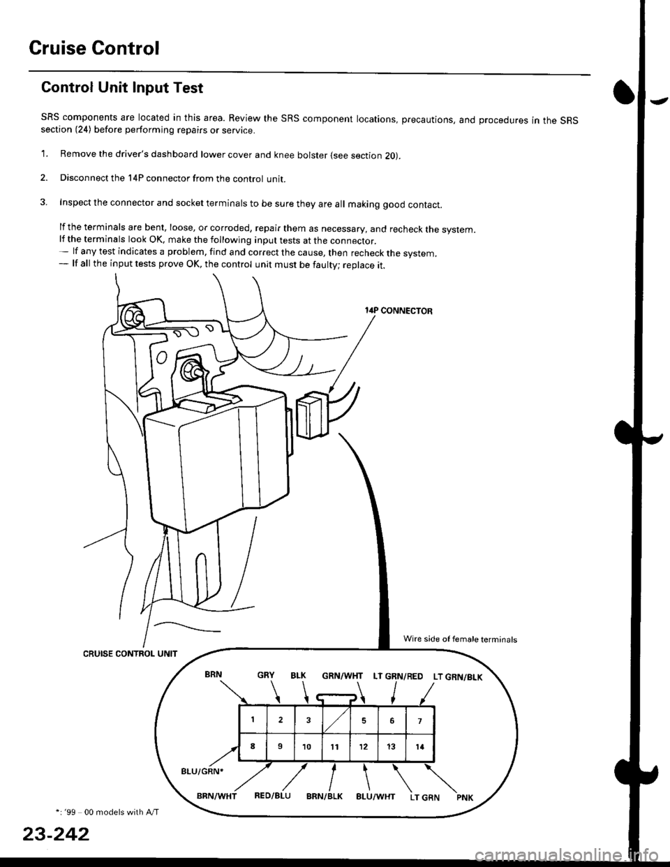
1. Remove the driver's dashboard lower cover and knee bolster (see section 20).
2. Disconnect the l4P connector from the control unit.
3. Inspect the connector and socket terminals to be sure they are all making good contact.
lf the terminals are bent, loose, or corroded, repair them as necessary, and recheck the system.lf the terminals look OK, make the following inpul tests at the connecror.- lf any test indicates a problem, find and correct the cause, then recheck the system,- lf all the input tests prove OK, the control unit must be faulty; replace it.
14P CONNECTOR
CRUISE CONTROL UNIT
*i '99 00 models with A/T
23-242
GRN/WHT LT GRN/RED LT GRN/BI-K
8LU/GRN*
Wire side of female terminals
Page 1714 of 2189
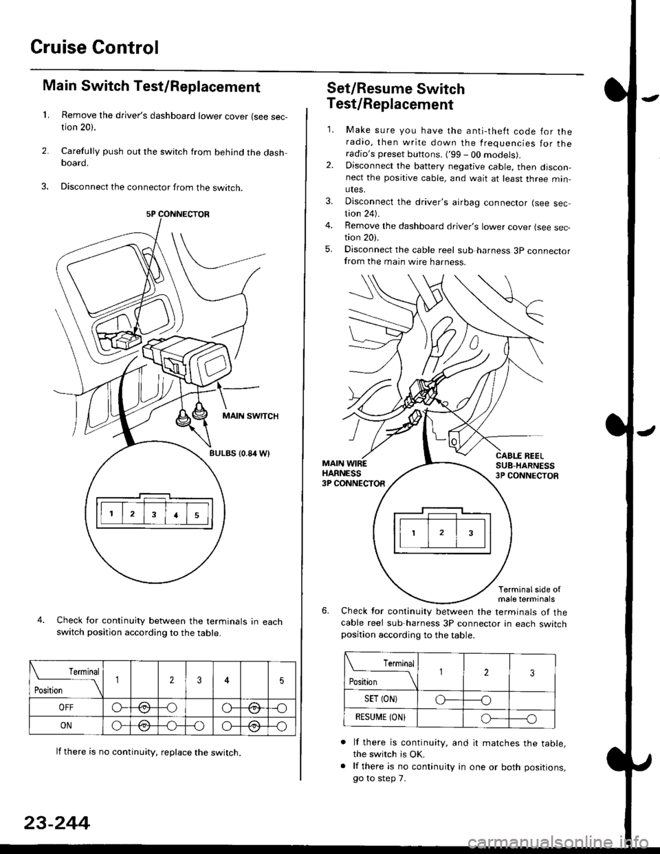
Cruise Gontrol
3.
1.
2.
Main Switch Test/Replacement
Remove the driver's dashboard lower cover (see sec-tion 20).
Carefully push out the switch from behind the dashboard.
Disconnect the connector from the swtrcn.
MAIN SWITCH
BULBS {0.84 Wt
Check for continuity between the terminals in eachswitch position according to the table.
lf there is no continuity. reDlace the switch.
4.
Terminal
r**
--\235
OFFo--oGa\-o\:./\a/
ONo-/a-oo--o\:/\:/
23-244
Set/Resume Switch
5.
Test/Replacement
2.
1.
MAIN WIREHARNESS3P CONNECTOR
Make sure you have the anti-theft code for theradio, then write down the frequencies for theradio's preset buttons. ('99 - 00 models).Disconnect the battery negative cable, then discon-nect the positive cable, and wait at least three min-utes.
Disconnect the driver's airbag connector (see sec-tion 24).
Remove the dashboard driver's lower cover (see sec,tion 20).
Disconnect the cable reel sub harness 3p connectorfrom the main wire harness.
CABLE BEELSUB-HARNESS3P CONNECTOS
Terminalside ofmale terminals
Check for continuity between the terminals of thecable reel sub-harness 3P connector in each switchposition according to the table.
L Terminal
Position123
SET (ON}o----o
BESUi,|E IONIo-----o
lf there is continuity, and it matches the table,the switch is OK.
lf there is no continuity in one or both positions,
go to step 7.
Page 1780 of 2189
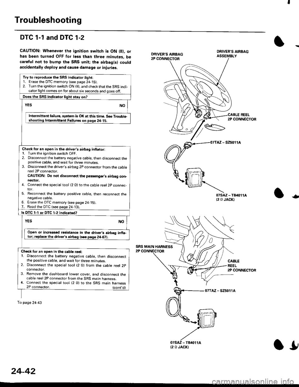
Troubleshooting
DTC 1-1 and DTG 1-2
CAUTION: Whenever the ignition switch is ON 0l), orhas been turned OFF for le33 than three minutes, becareful not to bump the SRS unit; the airbagls) couldaccidentally deploy and cause damage or inluries.
REEL2P CONNECTOR
AZ - SZ5011A
07sAz-TB{0t1At2 0 JACKT-
CABLEREEL2P CONNECTOR
07TAz - SZ5011A
DRIVER'S AIRBAG
SRS MAIN HARNESS
Try to reproduc€ the SRS indicator light:1. Erase the DTC memory lsee page 24,'15).2. Turn the ignition switch ON {ll), and check that the SRS indi-cator light comes on lor about six seconds and goes off.
Does the SRS indicator liqht 3tav on?
Intermittent lailure. system is OK at this time. So€ TloubleIntermittent Failur6 on Deqe 24-15.
Check for en open in th€ driver's airbag inllator:1. Turn the ignition switch OFF.2. Disconnect the battery negative cable, then disconnect thepositive cable, and wait for three minutes.3. Disconnect the driver's airbag 2P connector from the cablereel 2P connector.CAUTION: Do not disconnect the pa9,!eng6.,s ailbag con-nector.4. Connect the special tool {2 0)to the cable reel 2P connec,tor.5. Reconnect the battery positive cable, then reconnect thenegative cable,6. Erase the DTC memory {see page 24 15}.7. Read the DTC {see paqe 24-13).
ls OTC 1-1 or DTC 1-2 indicatod?
Open or incroas€d resistanc€ in the driver's ai.bag inoa-tor; r€place the d ve/s airbag lse6 pege 24€?).
Check for an opgn in the cabl6 reel:1. Disconnect the battery negative cable, then disconnectthe positive cable, and wait for three minutes.2. Disconnect the special tool {2 O) from the cable reel 2pconnector,3. Remove the dashboard lower cover, and disconnect thecable reel 2P connector from the SRS main harness.4. Connect the special tool {2 0} to the SRS main harness2P connector, {cont,
To page 24-43
(2 0 JACK)
24-42
l!
Page 1782 of 2189
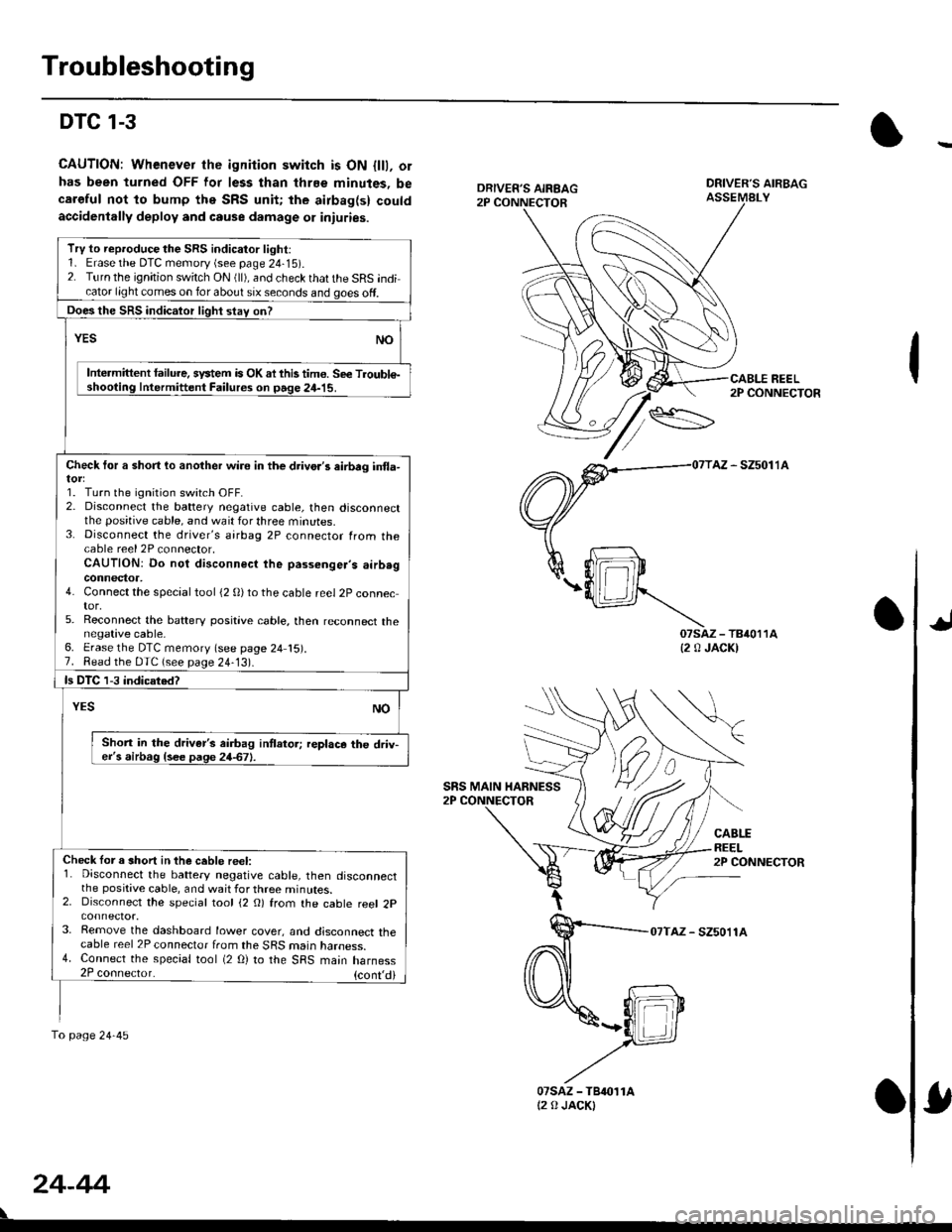
Troubleshooting
DTC 1-3
CAUTION: Whenever the ignition switch is ON {lll, orhas been turned OFF lor less than thrEe minutes, becaroful not to bump the SRS unit; the airbag(s) couldaccidenlally deploy and cause damage 01 iniuries.
DRIVER'S AIRBAGASSEMALY
REEL2P CONNECTOR
AZ - SZ5011A
07saz - TB4011A{2 0 JACK)
CABLEREEL2P CONNECTOR
07TAZ - SZ5011A
TrV to reproduce the SRS indicator light:1. Erase the DTC memory (see page 24-15).2. Turn the ignition switch ON (ll), and check that the SRS indicator light comes on for about six seconds and goes off.
Does the SRS indicalor light stav on?
YESNO
Intermittent lailure. system is OK ai this tim€. Se€ Troubl€-shooting Intermittent Failures on page 24-15.
Check tor a short lo another wire in the drivo.'s eirbrg in{la-
1. Turn the ignition switch OFF.2. Disconnect the battery negative cable, then disconnectthe positive cable, and wait for three minutes.3. Disconnect the driver's airbag 2P connector from thecable reel 2P connector,CAUTION: Do not disconnect the passenger's airb.gconnector,4. Connect the special tool (2 0)to the cable reel 2P connector,5. Reconnect the baftery positive cable, then reconnect thenegative cable,6. Erase the DTC memory (see page 24 15).7. Read the DTC (see page 24-13).
ls DTC 1-3 indicated?
NOYES
Shon in the driver's airbag intlator; replace the driv-er's airbag {see page 24-67}.
Check lor a short in the ceble reel:1. Disconnect the battery negative cable, then disconnectthe positive cable, and wait for three minutes.2. Disconnect the special tool (2 O) from the cable reel 2p
3. Remove the dashboard lower cover, and disconnect thecable reel 2P connector from the SRS marn naroess.4. Connect the special tool (2 O) to the SRS main harness2P coonector. {cont,di
fo page24-45
SRS MAIN HARNESS
24-44
07sAz - TBr011At2 0 JACKI
Page 1784 of 2189
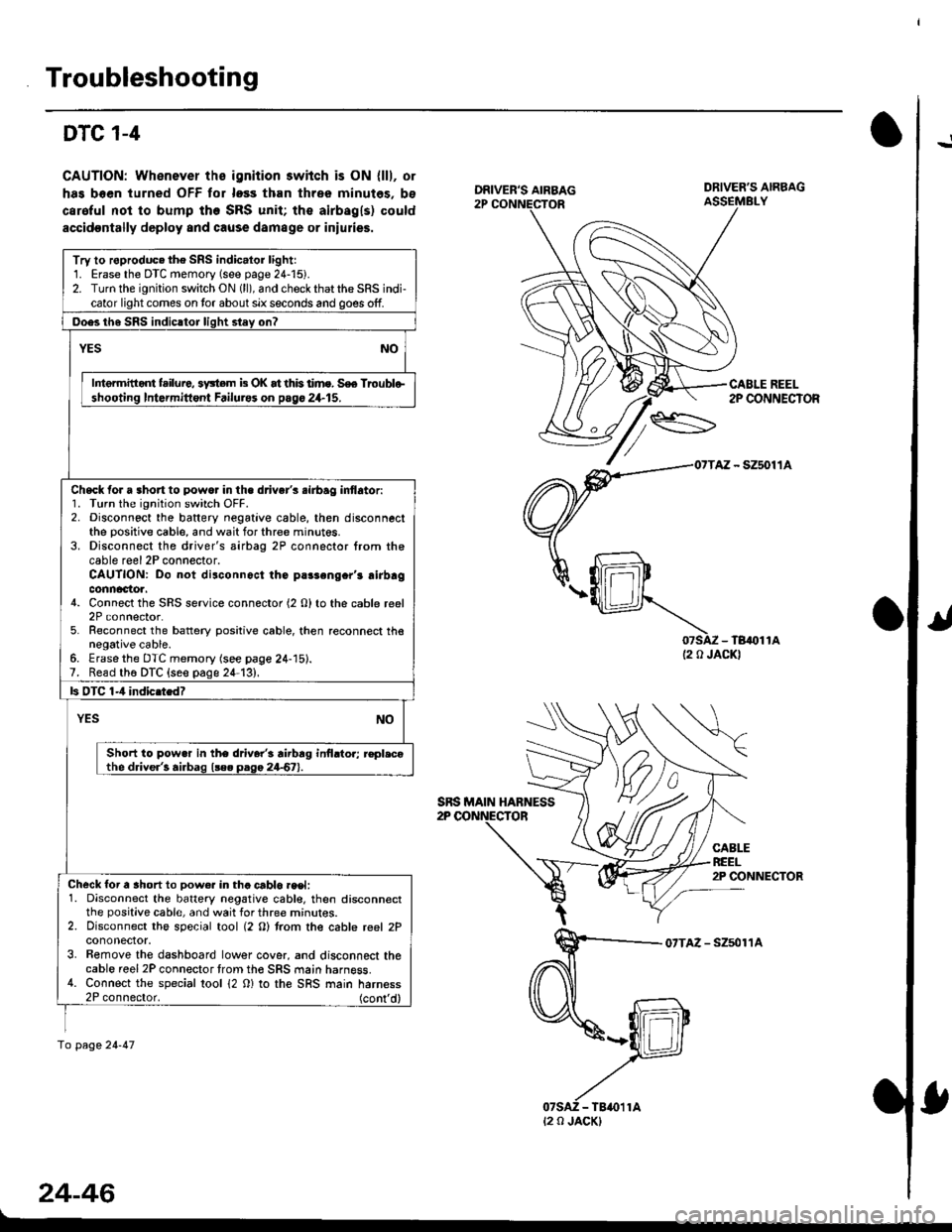
Troubleshooting
!DTC 1-4
CAUTION: Whenever ths ignition 3wiich is ON {lll, or
has boen turned OFF tor loss than three minutes, bs
caroful not to bump the SRS unit; the airbagls) could
accidoDtally deploy and cause damage or iniulies.
07SAZ - TB,()11A(2 0 JACKI
CABLEREEL2P CONNECTOR
07TAZ - Szsol'�lA
24-46
DRIVER'S AIRBAG
CABLE REEL2P CONNECTOR
Try to roproduc. the SRS indic.lor lightr1. Erase the DTC memory (see page 24-15).2. Turn the ignition switch ON (ll), and check that the SRS indi-cator light comes on tor about six seconds and goes off.
Ooes th6 SRS indicltor liqht stey on?
YESNO
Intermitid{ failure, 3y3tem b OK at this time. S€e Troublo-shooting Intormittont Failurss on pago 24.15.
Check for a 3hort to powo. in the d.iver's .irbag inflator:1. Turn the ignition switch OFF.2. Disconnect the baftery negative cable, then disconnectthe positive cable, and wait for three minut6s.3. Disconnect the driver's airbag 2P connector from thecable reel 2P connector.CAUTION: Do not disconnoct the parsengcr'r airbagconnactoa.4. Connect the SRS service connector (2 O) to the cable reel2P connector.5. Reconnect the battery positive cable, then reconnect thenegative cable.6. Erasethe DTC memory (see page 24-15).7. Read th6 DTC {seo page 24-13},
ls OTC 1-4 indic.tedT
YESNO
Short to pow.r in the driver'i rirbrg inilrtor; r€pl.cothe driver'! airbag l!e. paga 24-67).
Check for a ahort to Dow€r in tha crblo.eet:1. Disconnect the battery negative cabl€, then disconnectthe positive cable, and wait for three mrnur€s.2. Disconnect the special tool (2 O) trom the cable reel 2Pcononector.3. Bemove the dashboard lower cover, and disconnect thecable reel 2P connector trom th€ SRS main harness.4. Connect the special tool 12 0) to the SRS main harness2P connector. (cont'd)
fo page 24-47
SRS MAIN HABNESS
t2 0 JACK)