1997 HONDA CIVIC driver dashboard low cover
[x] Cancel search: driver dashboard low coverPage 873 of 2189

Description
The Continuously Variable Transmission (CVT) is an electronically controlled automatic transmission with drive and driv
en Oullevs, and a steel belt. The CVT provides non stage speeds forward and one reverse. The entire unit is positioned in
line with the engine.
Transmission
Around the outside of the flywheel is a ring gear which meshes with the starter pinion when the engine is being staned.
The transmission has four parallel shafts: the input shaft, the drive pulley shaft. the driven pulley shaft, and the secondary
gear shaft. The input shaft is in line with the engine crankshaft. The drive pulley shaft and the driven pulley shaft consist of
movable and fixed face pulleys. Both pulleys are linked by the steel belt.
The input shaft includes the sun gear. The drive pulley shaft includes the forward clutch which mounts the carrier assem-
bly on the forward clutch drum. The carrier assembly includes the pinion gears which mesh with the sun gear and the ring
gear. The ring gear has a hub-mounted reverse brake disc.
The driven pulley shaft includes the start clutch and the secondary drive gear which is integral with the park gear' The sec-
ondary gear shaft is positioned between the secondary drive gear and the final driven gear. The secondary gear shaft
includes the secondary driven gear which serves to change the rotation direction. because the drive pulley shaft and the
driven oullev shaft rotate the same direction. When certain combinations of planetary gears in the transmission are
engaged by the clutches and the reverse brake, power is transmitted from the drive pulley shaft to the driven pulley shaft
to provide E, E, E, and El.
Electronic Control'96 - 98 Models:
The electronic control system consists of the Transmission Control Module (TCM), sensors, three linear solenoids, and a
inhibitor solenoid. Shifting is electronically controlled under all conditions'
The TCM is located below the dashboard, behind the kick panel on the driver's side.'99 - 00 Models:
The electronic control svstem consists of a Powertrain Control Module (PCM), sensors, three linear solenoids and an
inhibitor solenoid. Shifting is electronically controlled under all conditions. A Grade Logic Control System to control shift-
ing in E position while the vehicle is ascending or descending a slope.
The PCM is located below the dashboard, under the kick panel on the passenger's side.
Hydraulic Control
The lower valve body assembly includes the main valve body, the Pressure Low (PL) reguiator valve body, the shift valve
body, the start clutch control valve body, and the secondary valve body. They are positioned on the lower part of the
transmission housing.
The main valve body contains the Pressure High (PH) control valve, the lubrication valve, and the pitot regulator valve.
The secondary valve body contains the PH regulator valve, the clutch reducing valve, the start clutch valve accumulator,
and the shift inhibitor valve. The PL regulator valve body contains the PL regulator valve and the PH-PL control valve
which is ioined to the PH,PL control linear solenoid. The inhibitor solenoid valve is bolted on the PL regulator valve body.
The shift valve body contains the shift valve and the shift control valve. which is joined to the shift control linear solenoid.
The start clutch control valve body contains the start clutch control valve, which is joined to the start clutch control linear
solenoid. The linear solenoids and the inhibitor solenoid are controlled by the TCM or PCM. The manual valve body which
contains the manual valve and the reverse inhibitor valve, is bolted on the intermediate housing.
The ATF pump assembly is located on the transmission housing, and is linked with the input shaft by the sprockets and
the sprocket chain. The pulleys and the clutch receive fluid from their respective feed pipes, and the reverse brake receives
fluid from internal hydraulic circuit.
Shift Control Mechanism
Input from various sensors located throughout the vehicle determines which linear solenoid the TCM or PCM will activate.
Activating the shift control linear solenoid changes the shift control valve pressure, causing the shift valve to move. This
pressurizes the drive pulley pressure to the drive pulley and the driven pulley pressure to the driven pulley and changes
their effective pulley ratio. Activating the start clutch control linear solenoid moves the start clutch control valve. The start
clutch control valve uncovers the port, providing pressure to the start clutch to engage it(cont'd)
14-195
,!
Page 1093 of 2189
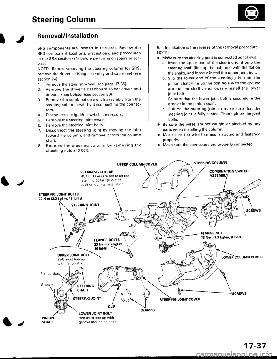
Steering Column
I
Removal/lnstallation
SRS components are located in this area. Review the
SRS component locations, precautions, and proceclures
in the SRS sectron (24) before pertorming repairs or ser-
vice.
NOTE: Before removing the steering column for SRS,
remove the driver's airbag assembly and cable reel lsee
section 24).
1. Remove the steering wheel (see page 17 35).
2. Remove the driver's dashboard lower cover and
driver's knee bolster (see section 20).
3. Remove the combination switch assembly from the
steering column sha{t by disconnecting the connec-
tors.
4. Disconnect the ignition switch connectors.
5. Remove the steering joint cover.
6. Bemove the steering joint bolls.
7. Disconnect the steering ioint by moving the joint
toward the column, and remove it from the column
shaft.
8. Remove the steering column by removing the
attaching nuts and bolt.
UPPER
RETAINING COLLABNOTE: Take care not to let the
retaining collar fall out ofposition during installation.
STEERING JOINT BOLTS22 N.m {2.2 kgf.m, 16lbtft}
9. Installation is the reverse of the removal procedure
NOTE:
. Make sure the steering joint is connected as follows:
a. Insert the upper end of the steering ioint onto the
steering shaft (line up the bolt hole with the flat on
the shait), and loosely install the upper joint bolt.
b. Slip the lower end of the steering joint onto the
pinion shaft (line up the bolt hole with the groove
around the shaft), and loosely install the lower
joint bolt.
Be sure that the lowei joint bolt is securely in the
groove in the pinion shaft.
c. Pull on the steering joint to make sure that the
steering joint js fully seated. Then tighten the ioint
bolts.
. 8e sure the wires are not caught or pinched by any
parts when installing the column
. Make sure the wire harness is routed and fastened
properly.
. Make sure the connectors are properly connected.
STEERING COLUMN
COMBINATION SWITCHASSEMBLY
FLANGE NUT13 N.m {1.3 kgl.m.9 lbf ft)
COLUMN COVER
FLANGE BOLTS22Nm12.2kgl'm,16 tbt.tr)
UPPER JOINT BOLTBolt musl line upon shaft.
Groove.
LOWER JOINT BOLT8oh must line up wrthgroove around on shaft.
CLIP
J
JOINT COVER
17-37
Page 1298 of 2189
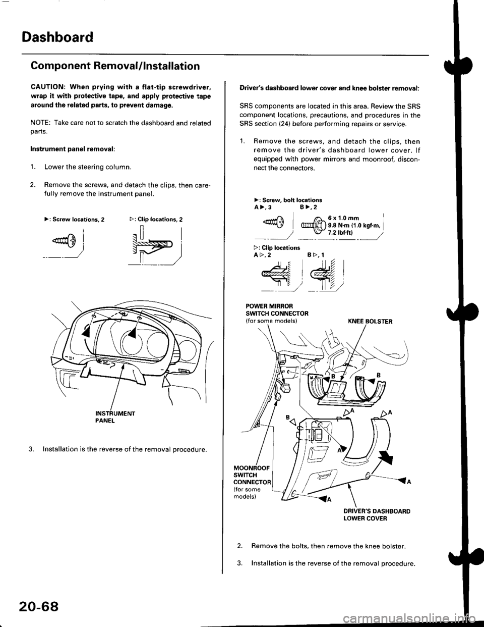
Dashboard
Component RemovaUlnstallation
CAUTION: When prying with a flat-tip screwdriver,
wrap it with protoctivo tape, and apply protective tape
around tho r6lat6d parts, to prevent damag6.
NOTE: Take care not to scratch the dashboard and relatedpans.
Instrument Danel removal:
1.Lower the steering column.
Remove the screws, and detach the clips, then care-
fully remove the instrument panel.
3. Installation is the reverse of the removal procedure.
>: Clip locations, 2
.il |
Pit)_ _ ,/
>: Screw locations,2
^l
@sl
:)
PANEL
20-68
Driver's dashboard lower cover and knee bolster removal:
SRS components are located in this area. Review the SRS
component locations, precautions. and procedures in the
SRS section (24) before performing repairs or service.
'1. Remove the screws, and detach the clips, then
remove the driver's dashboard lower cover. lf
equipped with power mirrors and moonroof, discon-
nect the connectors.
>: Screw, boh loc.tionsA>.3B>,2
_-rri I /a_6x1.0mm*\Y @{[) s 8 N'm tt o rst'm,
_-_- J _ \J- 7 2_rbtftl -_
>: Clip locationsA>.2 B >, 1
tu
DRIVER'S DASHBOARDLOWER COVER
Remove the bolts, then remove the knee bolster.
Installation is the reverse of the removal procedure.
Page 1299 of 2189
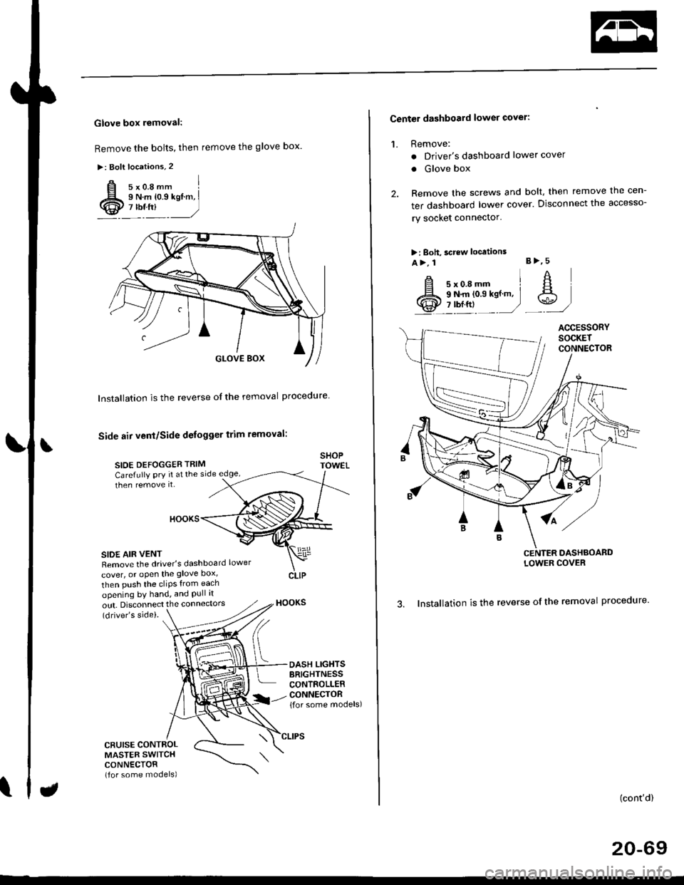
Glove box removal:
Remove the bolts, then remove the glove box.
>: Bolt locations,2
Installation is the reverse of the removal proceoure
Side air vent/Side defogger trim removal:
SIOE DEFOGGER TRIMSHOPTOWET_Carefully PrY rt at the
then remove it,side edge,
SIDE AIR VENTRemove the driver's dashboard lower
cover, or oPen the glove Dox,
HOOKS
then push the cliPs from each
opening by hand, and Pull it
out. Disconnect the connedors(driver's side).
HOOKS
DASH LIGHTSBRIGHTNESSCONTROLLERCONNECTOR{for some models)
CFUISE CONTROLMASTER SWITCHCONNECTOR(for some models)
Center dashboard lower covel:
1. Remove:
. Driver's dashboard lower cover
. Glove box
2. Remove the screws and bolt, then remove the cen-
ter dashboard lower cover. Disconnect the accesso-
ry socket connector'
>i Boh, screw locations
a>, 1 B>'5
A s*o.e-- I A
@;*;ry'-1'-.J _e)
3. Installation is the reverse of the removal proceoure'
(cont'd)
20-69
LOWER COVER
Page 1300 of 2189
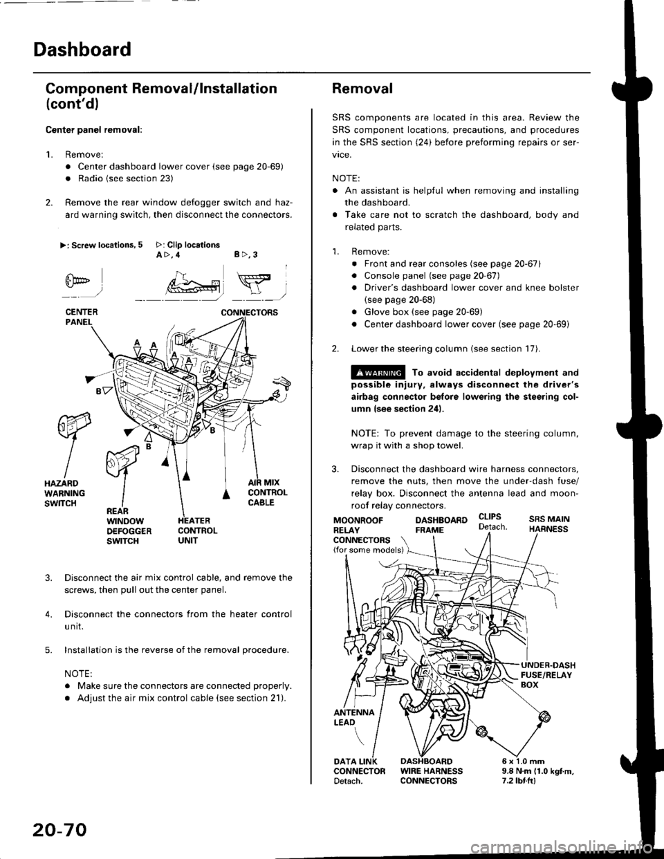
Dashboard
Gomponent Removal/lnstallation
(cont'd)
Center panel removal:
1. Remove:
. Center dashboard lower cover (see page 20-69)
. Radio {see section 23)
2. Remove the rear window defogger switch and haz-
ard warning switch, then disconnect the connectors.
>: Screw locations, 5 >: Clip locationsA>,4 B>,3
fii*-)
CENTERPANEI.
rt-xR.
W
IHAZARDWARNINGswlTcH
r44 "
F.IZvl
IIREARwtNoowOEFOGGERswtrcH
MtxCONTNOLCABLE
3. Disconnect the air mix control cable, and remove the
screws, then pull out the center panel.
4. Disconnect the connectors from the heater control
u nit.
5. Installation is the reverse of the removal procedure.
NOTE:
. Make sure the connectors are connected properly.
. Adjust the air mix control cable (see section 21).
20-70
Removal
SRS components are located in this area. Review the
SRS component locations, precautions, and procedures
in the SRS section (24) before preforming repairs or ser-
vice.
NOTE:
. An assistant is helpful when removing and installing
the dashboard.
. Take care not to scratch the dashboard, body and
related parts.
1. Remove:
o Front and rear consoles (see page 20-67)
. Console panel (see page 2O 67),
. Driver's dashboard lower cover and knee bolster(see page 20-68)
. Glove box (see page 20-69)
. Center dashboard lower cover (see page 20-69i
2. Lower the steering column (see section 17).
@ To avoid accidental deplovment and
possible injury, always disconnect the driver's
airbag connector belore lowering the steering col-
umn lsee section 241.
NOTE: To prevent damage to the steering column,
wrap it with a shop towel.
3. Disconnect the dashboard wire harness connectors,
remove the nuts, then move the under-dash fuse/
relay box. Disconnect the antenna lead and moon-
roof relay connectors.
DASHBOARD cltPs
CONNECTORS(for some models)
MOONROOFRELAY
ANTENNALEAO
FRAME
SRS MAINHARNESS
9.8 N.m (1.0 kgf m,7.2lbt.ltl
DATACONNECTOR WIRE HARNESSDetach. CONNECTORS
Page 1301 of 2189
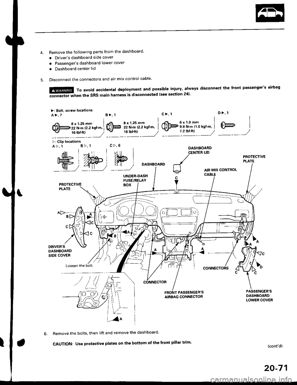
Remove the following parts Irom the dashboard'
. Driver's dashboard side cover
o Passenger's dashboard lower cover
. Dashboard center lid
Disconnect the connectors and air mix control cable'
6x1.0mm9.8 N.m 11.0 kgl.m,
D>, 1
@7 2'orftl - ---//_._J
,{nil Lll , ,"o
Ift#5 L //Hl Wlj%u|5 i//Wt qT
W72-t11 7'::--J
>: Clip locationsA>, 1 B>, 1
Loosen the bolt.
DASHBOARD
AIR MIX CONTROL
CONNECTORS
FRONT PASSENGER'SAIRBAG CONNECTOR
Remove the bolts, then lift and remove the dashboard'
CAUTION: Use proteqtive plates on the bottom ot the front pillar trim'(cont'd)
20-71
M,::;:"lx3T:iJnif:3lilH:fl"*:1::f"*'il;ili"'"
disconnect rhe front passeneer's airbas
>: Bolt, screw locaiions
A>,7B>, 1
,i( 8x125mm(!,@ 22 N.m t2.2 kstm,-v, 16 tbf.ftl
8xl.25mm I22 N.m 12.2 kgt'm, I'"tt:___J
c>, 1
@
c>,6
Page 1416 of 2189
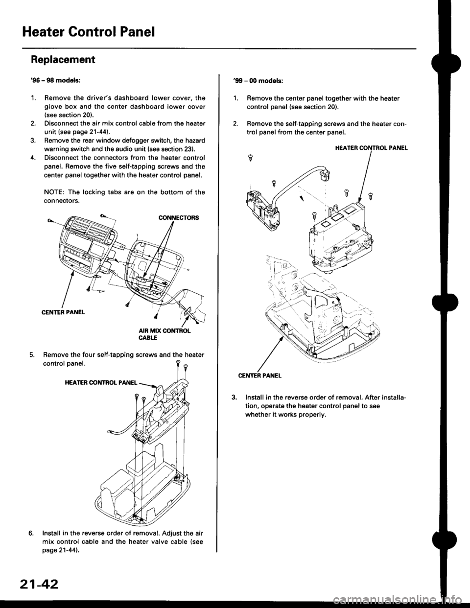
Heater Control Panel
'95 - 98 modolsi
Remove the driver's dashboard lower cover, the
glove box and the center dashboard lower cover(see section 20).
Disconnect the air mix control cabls from the heater
unit {see page 21-44).
Remove the rear window defogger switch, the hazard
warning switch and the audio unit (see section 23).
Disconnect the connectors from the heater control
panel. Remove the five self-tapping screws and the
center panel together with the heater control panel.
NOTE: The locking tabs are on the bottom of the
connecrors.
Install in the .everse order of removal. Adjust the air
mix control cable and the heater valve cable {seepage 21-44)..
Replacement
1.
Remove the four self-tapping screws and the heater
21-42
1.
'9!, - 00 modols:
Remove the center panel together with the heater
control panel (see section 20).
Remove the self-tapping screws and the heater con-
trol panelfrom the center Danel.
Install in the reverse order of removal. After
tion, operate the heater control panel to see
whether it works properly.
installa-
Page 1555 of 2189
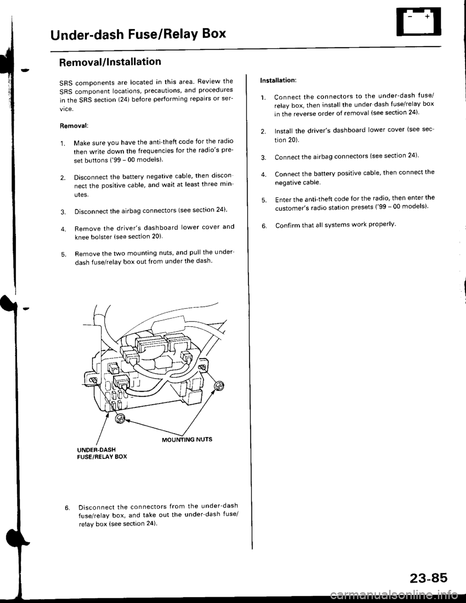
Under-dash Fuse/RelaY Box
Removal/lnstallation
SRS components are located in this area. Review lhe
SRS component locations, precautions, and procedures
in the SRS section (24) before performing repairs or ser-
vice.
Removal:
1. Make sure you have the anti-lheft code for the radio
then write down the frequencies lor the radio's pre-
set buttons ('99 - 00 modelsl.
2. Disconnect the battery negative cable. then discon
nect the positive cable, and wait at least three min
utes,
3. Disconnect the airbag connectors (see section 24)'
4. Remove the driver's dashboard lower cover and
knee bolster (see section 20)
5. Remove the two mounting nuts, and pull the under
dash fuse/relay box out from under the dash'
6. Disconnect the connectors from the under-dash
fuse/relay box, and take out the under-dash fuse/
relay box (see section 24).
lnstallation:
1. Connect the connectors to the under-dash tuse/
relay box, then install the under dash fuse/relay box
in the reverse order of removal (see section 24)'
2. Install the driver's dashboard lower cover (see sec
tion 20).
3. Connect the airbag connectors {see section 24)
4. Connect the battery positive cable, then connect the
negative cable.
5. Enter the anti-theft code lor the radio, then enter the
customer's radio station presets ('99 - 00 models)'
6. Confirm that all sYstems work properly'
23-45