1997 HONDA CIVIC parts
[x] Cancel search: partsPage 2 of 2189

INTRODUCTION
How to Use This Manual
This manual contains information for the 1996 - 2000 ClVlC. lt is
divided into 24 sections. The first page of each section is marked
with a black tab that lines up with its corresponding thumb index
tab on this page and the back cover. You can quicklY find the first
page of each section without looking through a tull table ol con_
tents. The symbols printed at the top corner of each page can also
be used as a quick reference system.
Each section includesl
1. A table of contents, or an exploded view index showing:
. Parts disassemblY sequence.
. Bolt torques and thread sizes.
. Page references to descriptaons in text
2. Disassembly/assembly procedures and tools.
3. Inspection.
4. Testing/troubleshooting.
5. Repair.
6. Adjustments.
Special Information
!@ Indicates a sttong possibility of sover. perconal iniurY
or loss ol lite if in3tructions are not follow€d.
GAUTION: Indicaiqs a possibility ot p€lsonal injury or 6quipm.nt
damage il instiuc'tions are not followod
t Noncali-. pu.po.. ot thes6 messages is to help provent demage lo lhe
vehicle, other property, or the €nvironment.
NOTE: Gives helpful information.
CAUTfON: Detaifed descriptions ol standard workshop p.oceduro3.
safoty principles and servico operations are not included. Pleaso
note that this manual contain3 wetnings and cautions against
some sp6cific sGrvic€ methods which could cause PERSONAL
INJURY, damage a vohicle or make il unsafe. Ploase undorstand
that these warnings cannot covsr all conceivable weys in which
service. whelher or not iocommgndod bY HONDA. mighi bo done,
or ol tho possiblG hazardou3 consgquonces of ev€aY conceivablg
way, nor could HONDA invqstigato all 3uch way3. AnYono using
sgrvice procedures or lools, whethei or nol rGcommendod bY
HONDA, must srtisty hifisetf thoroughlylhat nohher pefsonal sefety
nor vehiclc satsty will be reopardi2ed.
All intormation contained in this manual is based on the latest prod
uct information available at the time oI printing We reserve the
right to make changes at any time without notice No part of this
publication may be reproduced, stored in retrieval system, or trans'
mitted, in any form by any means, electronic, mechanical, photo
copying, recording, or otherwise, without the prior written permis-
sion of the publisher. This includes text, figures and tables.
*Transaxle
ds
First Edition 8/99 1848 PagesAll Right Reserved
HONOA MOTOR CO., LTD.
Sorvico Publication Offico
As sections with * include SRS components;
sDecial precautions are lequired when servlclng
*Electrical't
*SRSSRS
Page 35 of 2189

Warning/Caution Label Locations
A: CABLE REEL CAUTION A: '96 -99 model
TO SERVICE MANUAL FOR DETAILED INSTRUC.
TtoNs.
'00 model
ALLATION OF THE SRS CAELE REEL IS CRITICAL TO
THE PROPER OPERATION OF THE SRS SYSTEM. REFER TO
THE SERVICE MANUAL DETAILED INSTALLATION
INSTRUCTIONS.
(cont'd)
1-33
C: DRIVER MODULE OANGER
DANGEREXPLOSIVE/FLAMMABLECONTACT WITH ACIO. WATER OR HEAVY METALS SUCH
AS COPPER. I.EAD OR MERCURY MAY PRODUCE HARMFUL
AND IRRITATING GASES OR EXPLOSIVE COMPOUNDS,
STOBAGE TEMPERATURES MUST NOT EXCEED 2OO'F
I1(x}"CI. FOR PROPER HANDLING. STORAGE AND DISPOS.
AL PROCEDURES REFER TO SERVICE MANUAL. SRS SUP.
PLEMENT.POTSONCONTAINS POISONOUS SODIUM AZIOE AND POTASSIUM
NITRATE.FIRST AID:IF CONTENTS ARE SWALLOWED, INDUCE VOMITING, FOB
EYE CONTACT. FLUSH EYES WTTH WATER FOR 15 MINUTES.
IF GASES {FNOM ACIO OR WATEB CONTACTI ARE INHALED,
SEEK FRESH AIR. IN EVERY CASE, GET PBOMPT MEDICAL
ATTET,ITION.KEEP OUT OF REACH OF CHILDREN.
Br oRIVER MODULE WARNING
WARNINGTHE AIRBAG INFLATOR IS EXPLOSIVE AND, IF ACCIOEN-
TALLY DEPLOYEO, CAN SERIOUSLY HURT OR KILL YOU.. DO NOT USE ELECTRICAL TEST EoUIPMENT oR PROB-
ING OEVICES.THEY CAN CAUSE ACCIDENTAL DEPLOYMENT.o NO SERVICEABLE PARTS lNSlDE. DO NOT
DISASSEMBLE.. PLACE AIRBAG UPRIGHT WHEN REMOVED.. FOLLOW SERVICE MANUAL NSTBUCTIONS CAFEFULLY.
Page 45 of 2189

Towing
lf the vehicle needs to be towed, call a professional tow-
ing service. Never tow the vehicle behind another vehi
cle with iust a rope or chain lt is very dangerous'
Emergency Towing
There are three popular methods of towing a vehicle:
Flat-bed Equipment - The operator loads the vehicle on
the back of a truck. This is the best way of transporting the
vehicle.
Wheel Lift Equipment - The tow truck uses t\ivo pivoting
arms that go under the tires {front or rear} and lifts them
off the ground. The other two wheels remain on the
ground.
Sling-type Equipment - The tow truck uses metal cables
with hooks on the ends. These hooks go around parts of
the frame or suspension, and the cables lift that end of
the vehicle off the ground The vehicle's suspension and
body can be seriously damaged if this method of towing
is attemDted.
lf the vehicle cannot be transported by flat-bed. it should
be towed with the front wheels off the ground lf due to
damage, the vehicle must be towed with the front
wheels on the ground, do the following:
lvlanual Transmission and CW
. Release the parking brake
. Shift the transmission to neutral (CW to E position)'
Automatic Transmission
. Release the Parking brake.
. Sta rt the engine.
. Shift to LDll position, then E position.
. Turn oif the engine
CAUTION;
o lmploper towing preparation will damage ihe tfans-
mission. Follow the above procedute exaqtly lf you
cannot shift the tlansmission or start the engino
laulomatic transmissionl, yout vehicle must be trans-
ported on a flat-bed.
. lt is best to tow the vehicle no farther than 50 mil€s
(80 km), and ksop thE speed below 35 mph (55 km/hl
. Trying to lift 01 tow your vehicle by tho bump€F will
caus€ setious damagg. Ths bumpers are not dEigned
to supportthe vshicle's weigh.
tJO
1-43
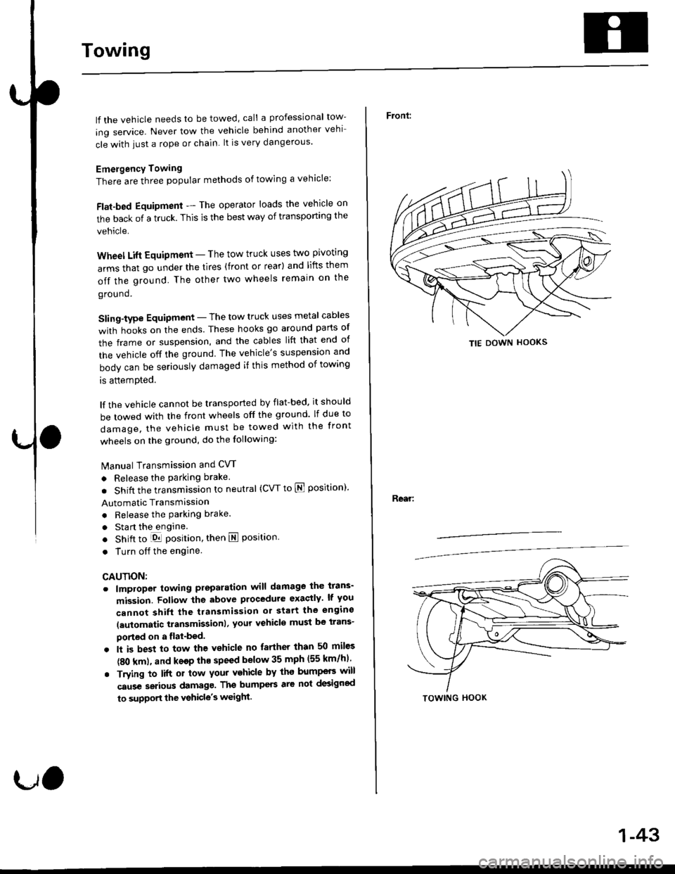
Front:
Rear:
TIE DOWN HOOKS
TOWING HOOK
Page 96 of 2189

Engine RemovaUlnstallation
Removal
@@
1.
. Make sure iacks and salety stands are placed ploperly
and hoist brackets are attached to the correct posi-
tions on the engine.
. Make sure the vehicle will not roll off stands and fall
while you are working under it.
CAUTION:
. Use fender covers to avoid damaging painted sur-face.
. Unplug the wilin9 connectors caretully while holdingthe conngstor portion to avoid damage,. Mark all wiring and hosos to avoid misconnoction.
Also, be sure that they do not contact other wiring or
hoses or interfere with other parts,
Secure the hood as open as possible.
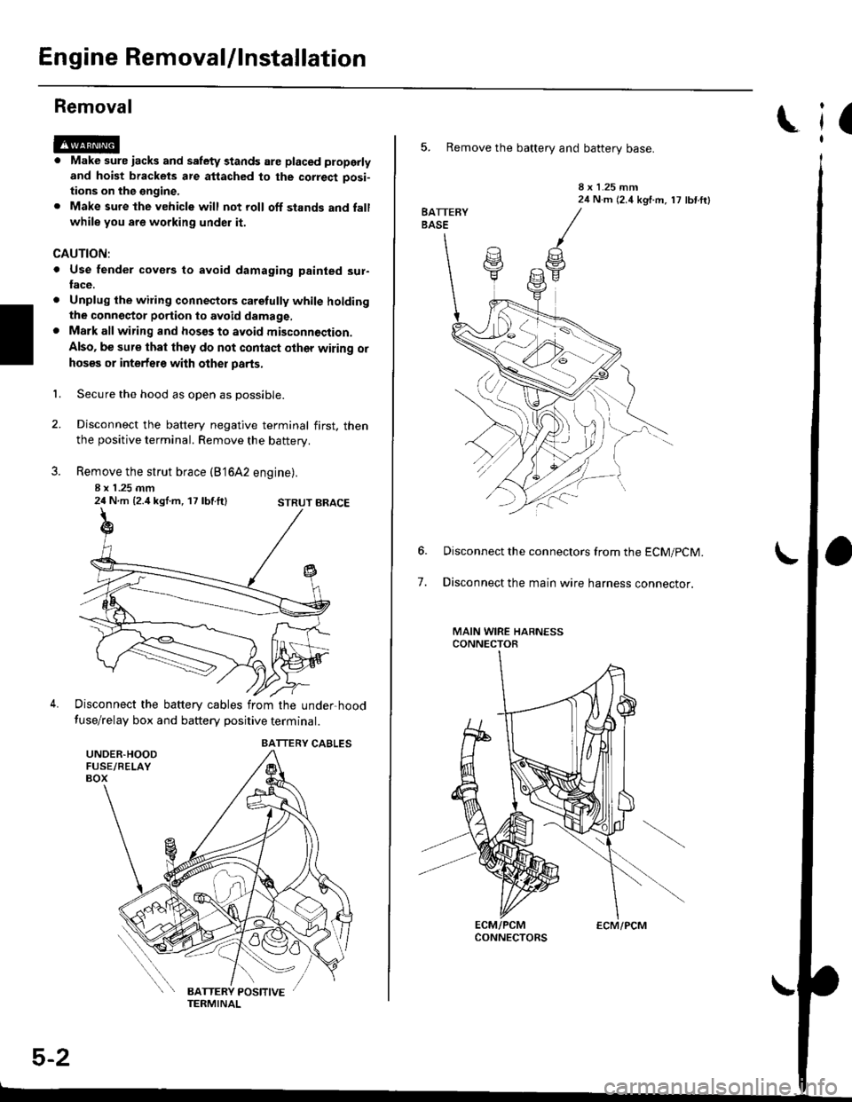
Disconnect the battery negative terminal first. thenthe positive terminal. Remove the battery.
Remove the strut brace (B'16A2 engine).
8 x 1 .25 mm24 N.m {2.4 kgl.m, 17 lbf.ft}
Disconnect the battery cables from the under-hood
fuse/relay box and battery positive terminal.
STRUT BRACE
UNDER.HOODFUSE/RELAYBOX
BATTERY CABLES
5-2
ECM/PCM
(
5. Remove the battery and battery base.
8 x 1.25 mm24 N.m (2.4 kgf.m, 17 lbf ftl
7.
Disconnect the connectors from the ECM/pCM.
Disconnect the main wire harness connector.
MAIN WIRE HARNESSCONNECTOR
Page 135 of 2189

Cylinder Head
lllustrated Index (cont'dl
(-/) _.- E "or to reassembring, crean at the parts in sorvent, dry them and appry rubricant to anv contact oarts.
D16Y7 engine:
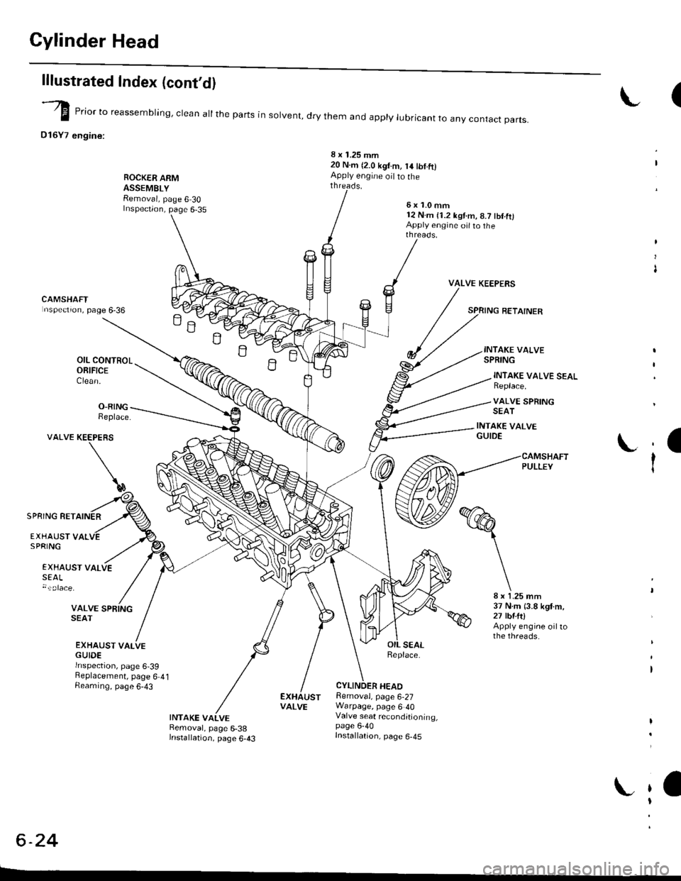
ROCK€R ARMASSEMBLYRemoval, page 6 30Inspection, page 6-35
8 x 1.25 mm20 N.m (2.0 kgt.m, 14 tbt.ftlApply engine oil to the
H
B
O-RINGReplace.
INTAKE VALVE SEALReplace.
VALVE SPRINGSEAT
INTAKE VALVEGUIDE
:a
ti
VALVE
SPRING RETAINER
EXHAUST VALVESEAL
VALVE SPRINGSEAT
EXHAUST VALVEGUIDErnspectron, page 6,39Beplacement, page 6 4lAeaming, page 6-43
8 x 1.25 mm37 N m (3.8 kgt m,27 tbtftlApply engine oiltothe threads.
INTAKE VALVERemoval, page 6-38lnstallation, page 6-43
Removal, page 6,27Warpage, page 6 40Valve seat reconditioning,page 6-40Installation, page 6-45
VALVE
t
t
t
CAMSHAFTnspectron, page 6-36
OIL CONTROLORIFICEClean.
KEEPERS
\
EXHAUST VALSPRING
c -A9-2.+
L
6x1.0mm12 N.m (1.2 kst.m, 8.7 tbf.ft)Apply engine oit to thethreads.
VALVE KEEPERS
SPRING RETAINER
INTAKE VALVESPRING
Page 137 of 2189

Cylinder Head
lllustrated Index (cont'dl
VALVE KEEPERS
SPRING RETAINER
INTAKE VALVE
VTEC SOLENOIDVALVE FILTEBReplace.
OIL CONTROLORIFICEClean.
INTAKE VALVE SEALReplace.VALVE SPRINGSEAT
INTAKE VAI.VEGUIOE
CAMSHAFTPULLEY
I
I
VALVE KEEPERS
SPRING RET
EXHAUST VALVESPRING
@
EXHAUST VALVESEALReplace.
8 x 1.25 mm37 N.m 13.8 kgt m,27 tbfitlApply engine oiltothe threads.
EXHAUSTVALVE
-vp
e,.io"o reassembring, crean at the parts in sorvent, dry them and appry rubricant to any contact parts.
D16Y8 engine:
LOST MOTIONASSEMgLY
ROCKER ARMASSEMBLYRemoval, page 6 30Inspection, page 6-34
5xl.0mm12 N.m {1.28.7 tbf.ft)
VALVE SPRINGSEATEXHAUSTVALVE O.RINGGUIDE Replace.Inspection, page 6 39Replacement, page 6 41Reaming, page 6 43
LOST MOTIONASSEMBLYHOLDER
INTAKE VALVEBemoval, page 6 38Installation, page 6 43
20 N.m 12.0 kgl.m, 14 tbf.ft)Apply engine oit to thethreads.
\
\
s9illl
CAMSHAFTInspection, page 6-36
OIL SEALBeplace.
CYLINDER HEADRemoval, page 6 27Warpage, page 6-40Valve seat reconditioning,page 6 40Installation, page 6-45
6x1.0mm12 N.m (1.2 kgt.m,8.7 lbf.ftlApply engine oil to thethreads,
Page 138 of 2189

Removal
Engine removal is not required for this procedure
!!!s@ Make sure iacks and salety stands are
f ta"eata"ea propetty and hoist brackets are attached to the
correct positions on the engine.
CAUTION:
. Use tender covels to avoid damaging painted sul-
faces.
o To avoid damage, unplug the wiling connectors
carefully while holding the connector portion to
avoid damage.
. To avoid damaging the cylinder head, wait until the
engine coolant temperature drops below 100"F
{38"C} before loossning the tetaining bolts.
NOTE:
o Mark all wiring and hoses to avoid misconnectlon
Also, be sure that they do not contact other wiring or
hoses, or interfere with other parts.
. Inspect the timing belt before removing the cylinder
h ead.
. Turnthe crankshaft pu lley so that the No. lpistonisat
top dead center (see Page 6-21)
'1. Disconnect the negative terminal from the battery'
Drain the engine coolant (see page'10-7).
a Remove the radiator cap to speed draining.
Remove the intake air duct and air cleaner housing
(see page 5 3).
Remove the mounting bolt and lock bolt. then
remove the power steering (P/S) pump belt and
pump (see page 5'5).
Loosen the idler pulley center nut and adjusting
bolt' then remove the air conditioning (A'lc) com-
pressor belt (see Page 5-6).
Loosen the mounting nut and lock bolt. then
remove the alternator belt (see page 6-19).
Remove the P/S pump bracket (see page 5-12).
3.
4.
2.
6.
1.
8. Remove the throttle cable by loosening the locknut,
then slip the cable end out of the throttle linkage
NOTE:
. Take care not to bend the cable when removing it
Always replace any kinked cable with a new one
. Adjust the throttle cable when installing (see sec-
tion 1 1).
D16Y7 engine:
Dl6Y5, Dl6Y8 engines:
THFOTTLECABLE
(cont'd)
6-27
LOCKNUT
CABLE
Page 142 of 2189

Disassembly/Reassembly
NOTE:
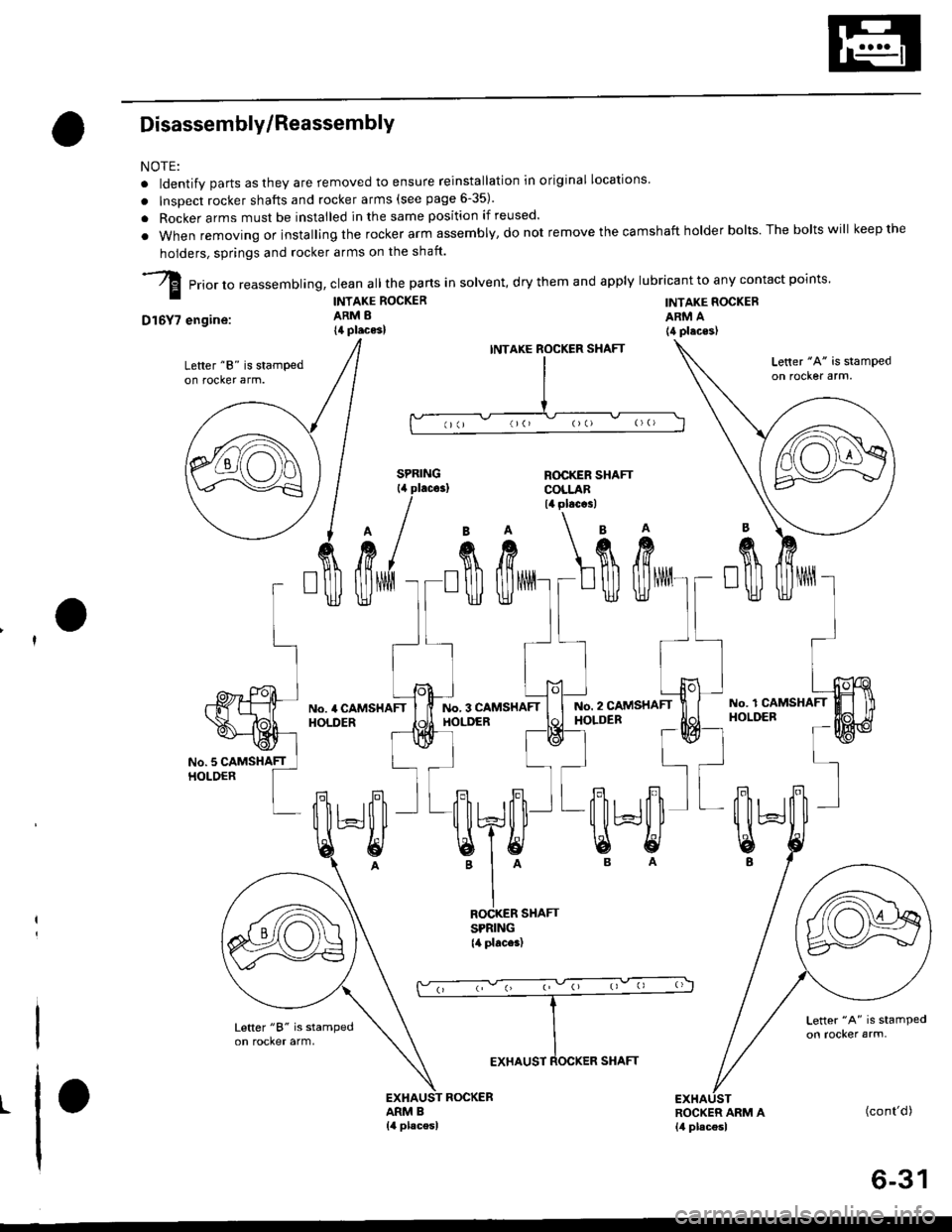
. ldentify parts as they are removed to ensure reinstallation in original locations'
. lnsDect rocker shafts and rocker arms (see page 6-35).
. Rocker arms must be installed in the same position if reused.
. when removing orinstallingthe rocker arm assembly,donot remove the camshaft holder bolts. The boltswill keepthe
holders, springs and rocker arms on the shaft.
-Zl prio, ,o reassemblinq, clean all the pans in solvent, dry them and apply lubricant to any contact points.
| - TNTAKE RocKER TNTAKE RocKER
D16Y7 engine:
Lefter "8" is stampedon rocker arm.
ARM A(4 placeslARM B
14 places)
INTAXE
ROCKER SHAFTSPRING{4 places)
ROCKER SHAFTCOLLAR14 plac.3l
ROCKER
I
II
I
BA\'A
fift L$\ft
:oo)[*o:
llll.I Jol----tNo.3 CAMSHAFT | | ruo. z cltusxerr 1i
T-* l=Bl-* d
,", 'l l=^ ^l
qJ?[l'-qJ'Ll
'I^ B A
EI
[ilHl"\9
t(cont'd)
6-31