1997 HONDA CIVIC Front
[x] Cancel search: FrontPage 1748 of 2189
Preca utions/Procedures
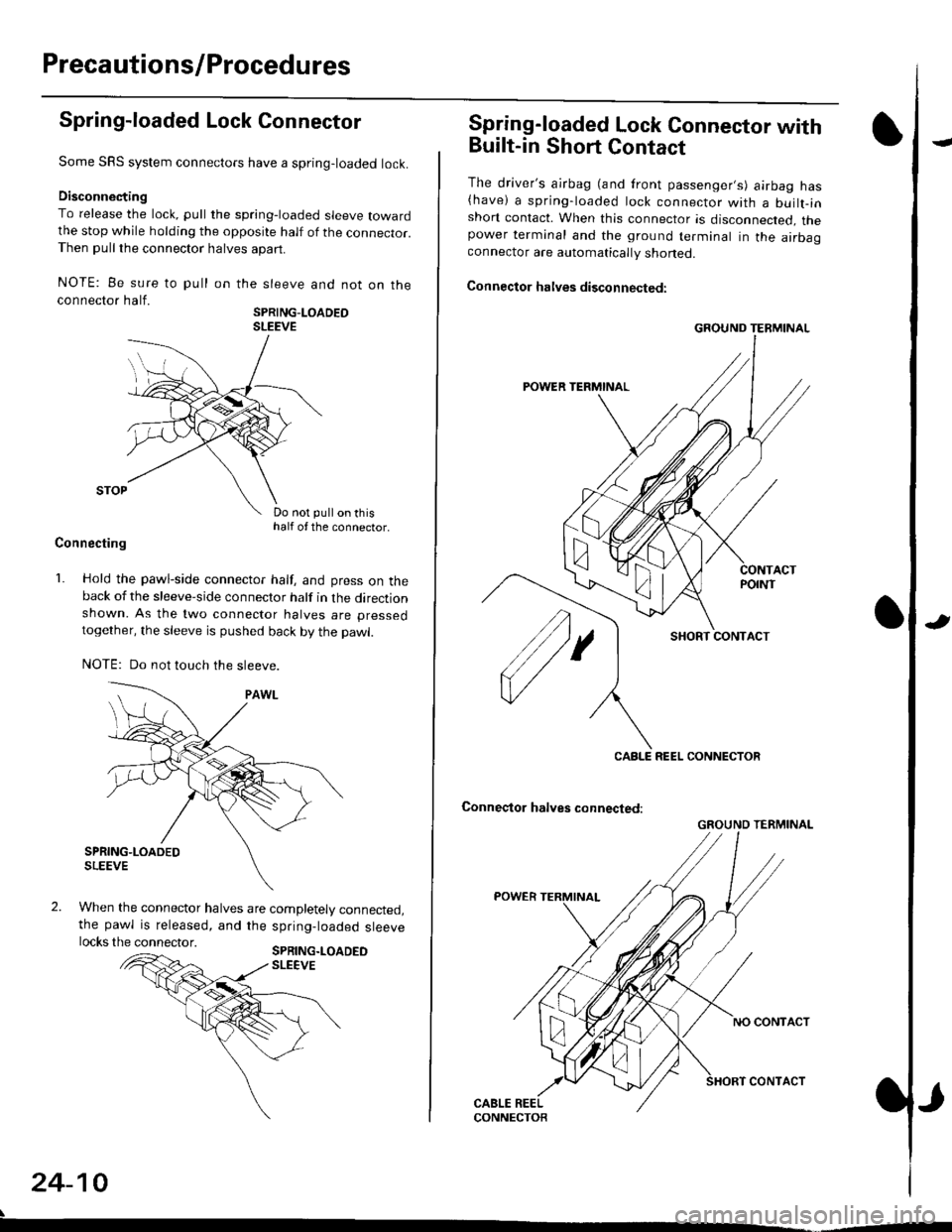
Spring-loaded Lock Connector
Some SRS system connectors have a spring-loaded lock.
Disconnecting
To release the lock, pull the spring-loaded sleeve towardthe stop while holding the opposite half of the connecror.Then pull the connector halves apart.
NOTE: Be sure to pull
connector half.
on the sleeve and not on the
SPRING-LOADEOSLEEVE
Do not pull on thishalf of the connector.
Connecting
1. Hold the pawl-side connector half, and press on theback of the sleeve-side connector half in the directionshown. As the two connector halves are pressed
together, the sleeve is pushed back by the pawl.
NOTE: Do not touch the sleeve.
When the connector halves are completely connected,the pawl is released, and the spring-loaded sleevelocks the connector.SPRING.LOADEDSLEEVE
24-10
Spring-loaded Lock Connector with
Built-in Short Contact
The driver's ajrbag (and front passenger,s) airbag has(have) a spring-loaded lock connector with a builr-inshort contact. When this connector is disconnected, thepower terminal and the ground terminal in the airbaaconnector are automatically shoned.
Connector halves disconnected:
SHORT CONTACT
Conneqtor halves connected:
GROUND TERMINAL
CABLE REEL CONNECTOR
GROUND TERMINAL
Page 1749 of 2189
)Disconnecting the Airbag Connector(sl
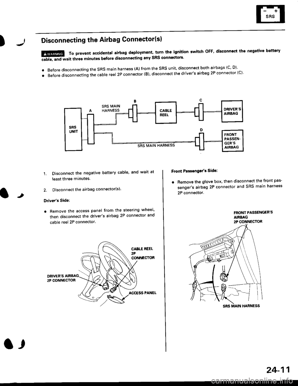
'1. Disconnect the negative battery cable, and wait at
least three minutes.
2. Disconnect the airbag connector(sl.
Driver's Side:
. Remove the access panel from the steering wheel'
then disconnect the driver's airbag 2P connector and
cable reel 2P connector.
!@@ To prevent sccidental 8irbag deployment, turn th€ ignition switch oFF. disconncct th€ negative battery
ffi, "nd *"it thr"e minutes b€fore disconnocting any sRS conn'ctors'
. Before disconnecting the SRS main harness (A) from the SRS unit' disconnect both airbags (C' D)'
.Beforedisconnectingthecab|ereel2Pconnector(B),disconnectthedriver,sairbag2Pconnector(c).
F ont PasEanga/3 Side:
. Remove the glove box. then disconnect the front pas-
senger's airbag 2P connector and SRS main harness
2P connector.t
FRONT PASSENGER'SAIRBAG2P CONNECTOR
CABTT REEL2?CONNECTOR
AOCESS PANEL
a,
24-11
Page 1751 of 2189
rl
Troubleshooting
t)
Self-diagnostic Procedures
The self-diagnostic function of the SRS system allows it to locate the causes of system problems and to store this informa' I
tion in memory. For easier troubleshooting, this data can be retrieved via a data link circuit l
. When you turn the ignition switch ON (ll), the SRS indicator will come on. ll it goes off after six seconds. the system is
norma l.
. lf there is an abnormality, the system locates and defines the problem, stores this information in memory, and turns
the sRS indicator light on. The data will remain in the memory even when the ignition switch is turned off or if the bat-
tery is disconnected.
o when you connect the scs service connector to the service check connector (2P), and turn the ignition switch oN (ll),
thesRsindicator|ightwi||indicatethediagnostictroub|ecode(DTC)bythenumberofb|inks.
. After reading and recording the DTC. proceed with the troubleshooting for this code'
Precauiions
.Useon|yadigita|mU|timetertocheckthesystem'|fit,snotaHondamu|timeter,makesureitsoutputisl0mA(0.01A)
or|esswhenSwitchedtothesma||estva|ueintheohmmeterrange,AtesterwithahigheroUtpUtcoulddamagethe��
airbag circuit or cause accidental airbag deployment and possible injury'
r when-ever the ignition switch is oN (ll). or has been turned oFF for lessthan three minutes, be careful nottobumpthe
SRS unit; the airbags could accidentally deploy and cause damage or injuries
. Before you ,"n1ou" th" SRS main harness, disconnect the driver's airbag connector (and the front passenger's airbag
connector).
. Make sure the battery is sufficiently charged {see section 23}. lf the battery is dead or low, measuring valLles won t be
correct.
. Do not touch a tester probe to the terminals in the sRS unit or harness connectors, and do not connect the terminals
with a jumper wire. Use only the backprobe set or the special tools'
For backprobing spring-loaded lock type connectors, refer to page 24-9'
Reading the DTC
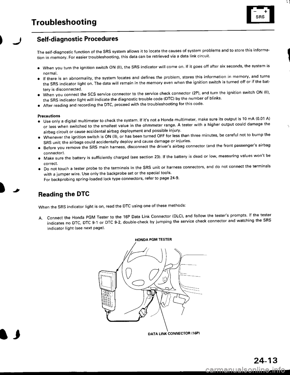
when the SRS indicator light is on, read the DTC using one of these methods:
A. Connect the Honda PGM Tester to the 16P Data Link Connector {DLC), and follow the tester's prompts lf the tester
indicatesnoDTc,DTcg-1orDTc9-2,doub|e-checkbyjumpingtheservicecheckconnectorandwatchingthesRS
indicator light (see next Page)
HONDA PGM TESTER
DATA LINK CONNECTOR Il6PI
l,
24-13
Page 1755 of 2189
l
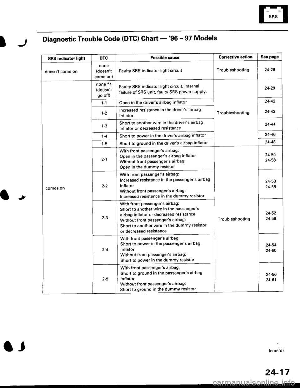
Diagnostic Trouble Code (DTG) Chart -'96 - 97 Models
t
SRS indicator lightDTCPossible causeCorrectiv6 actionSae page
doesn't come on
none(doesn't
come on)
Faulty SRS indicator light circuitTroubleshooting24-26
comes on
none *4
(doesn't
go off)
Faulty SRS indicator light circuit, internal
failure of SRS unit, faulty SRS power supply.
Troubleshooting
24-29
1-1Open in the driver's airbag inflator24-42
lncreased resistance in the driver's aarbag
inflator24-42
l-3Short to another wire in the driver's airbag
inflator or decreased resistance
Short to Dower in the driver's airbag inflator
Short to ground in the driver's airbag inflator
24-44
1-424-46
1-524-48
2-1
With front passenger's airbag:
Open in the passenger's airbag inflator
Without front Passenger's airbag:
ODen in the dummy resistor
24-50
24-54
With front passenger's airbag:
Increased resistance in the passenger's airbag
inflator
Without front Passenger's airbag:
lncreased resistance in the dummy resistor
24,50
24-54
2-3
With front passenger's airbag:
Shon to another wire in the passenger's
airbag inflator or decreased resistance
Without tront passenger's airbag: Troubleshooting
Short to another wire in the dummy resistor
or decreased resistance
24-52
24-59
2-4
With front passenger's airbag:
Short to power in the passenger's airbag
inJlator
Without front Passenger's airbag:
Short to power in the dummy resistor
24-54
24-60
With front passenger's airbag:
Short to ground in the passenger's aarbag
inflator
without front passenger's airbag:
Short to ground in the dummy resistor
24-56
24-61
(cont'd)
24-17
a,
Page 1757 of 2189
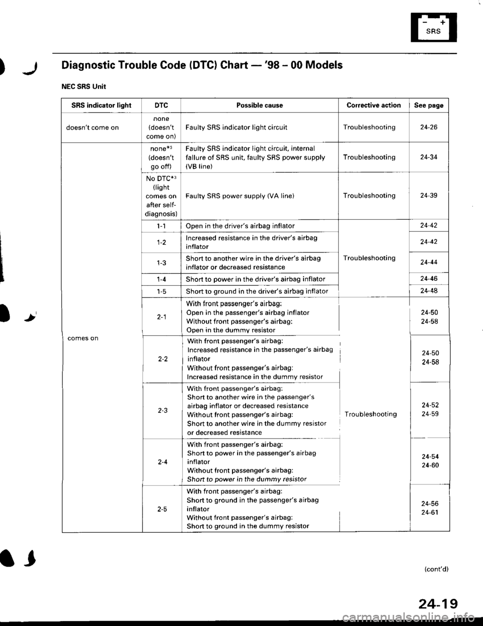
)Diagnostic Trouble Code (DTC) Chart -'98 - 00 Models
NEC SRS Unit
Ir
SRS indicator lightDTCPossible causeCorrestive actionSee page
doesn't come on
none
(doesn't
come on)
Faulty SRS indicator light circuitTroubleshooting24-26
comes on
none*3
(doesn't
go off)
Faulty SRS indicator light circuit, internal
fallure of SRS unit, faulty SRS power supply
(VB line)
Troubleshooting24-34
No DTC*3(lis ht
comes on
after self-
diagnosis)
Faulty SRS power supply (VA linelTroubleshooting24-39
l-1Open in the driver's airbag inflator
Troubleshooting
24 42
Increased resistance in the driver's airbag
inflator24-42
Short to another wire in the driver's airbag
inflator or decreased resistance24-44
't -4Short to power in the driver's airbag inflator24-46
t-5Short to ground in the driver's airbag inflator24-48
With front passenger's airbag:
Open in the passenger's airbag inflator
Without front passenger's airbag:
Open in the dummv resistor
24-50
24-54
With front passenger's airbag:
Increased resistance in the passenger's airbag
inflator
Without front passenger's airbag:
Increased resistance in the dummy resistor
24-50
24-58
with front passenger's airbag:
Short to another wire in the passenger's
airbag inflator or decreased resistance
Without front passenger's airbag:
Short to another wire in the dummy resistor
or decreased resistance
Troubleshooting
24-52
24,59
2-4
With front passenger's airbag:
Short to power in the passenger's airbag
inflator
Without front passenger's airbag:
Shon to power in the dummy resistor
24-54
24-60
With front passenger's airbag:
Short to ground in the passenger's airbag
inflator
Without front passenger's airbag:
Short to ground in the dummy resistor
24-56
24-61
(cont'd)
24-19
l,
Page 1766 of 2189
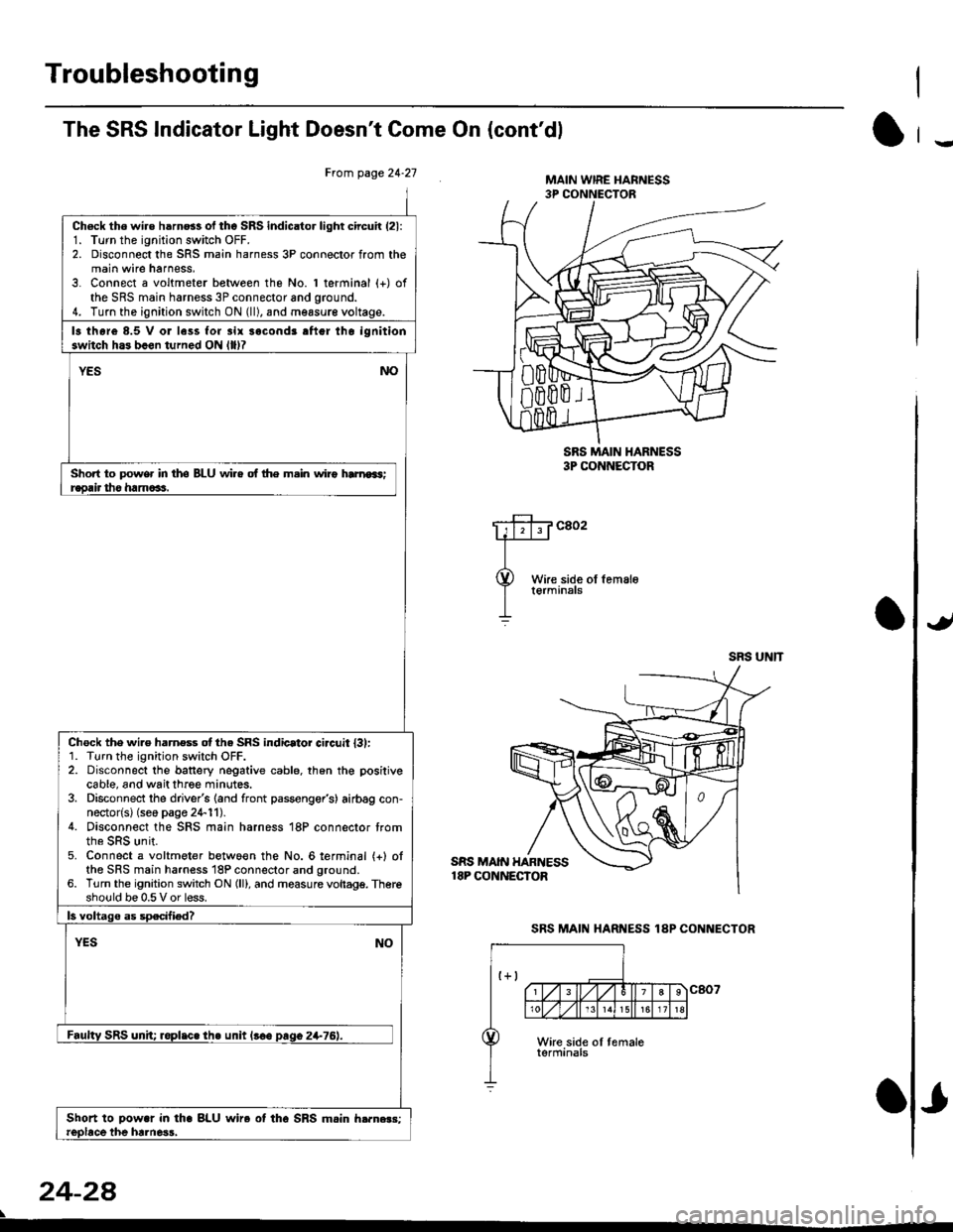
Troubleshooting
The SRS Indicator Light Doesn't Come On (cont'dl
Frcm page 24.21
Ch6ck tho wire h6rn6s of tho SRS indicator light circuir (21:
1. Turn the ignition switch OFF.2. Disconnect the SRS main harness 3P connector from themain wire harness,3. Connect a voltmeter between the No. 1 terminal (+) ofthe SRS main harness 3P connector and ground.4. Turn the ignition switch ON (ll), and measur€ voltage.
13 thore 8.5 V or less for 3ir sacond3 aftgr tho ignitionswitch h.3 b.en turned ON llllT
YESNO
Short to power in tho BLU wi.e of lhe m.in wiro hrnroas;r€orir tho ham6as.
Chock the wi.e harness otthe SRS indicator ci.cuit l3l:1. Turn the ignition switch OFF.2. Disconnect the banery negative cable. th6n the positivecable, and wait three minutes.3. Disconnect the driver's (and front passenger's) airbag con-nector{s} (seo page 24-11).4. Disconnect the SRS main harness 18P connector trom
5. Connect a voltmeter betwo€n the No. 6lerminal {+} ofthe SRS main harness 18P connector and ground.6. Turn the ignition switch ON (ll), and measure vollagg. Thereshould be 0.5 V or less.
ls voltago as specified?
YESNO
Faultv SRS unh; roplic. the unit l!€e paqo 2+76).
Shoft to Dowar in tha BLU wire ot tho SRS mein h.rn.r3:reobce the hrlne3s,
24-2a
SRS MAIN HARNESS18P CONNECTOR
MAIN WIRE I{ARNESS3P CONNECTOR
SRS MAIN I{ARNESS3P CONNECTOR
c802
SRS UNIT
SRS MAIN HARNESS 1AP CONNECTOR
-
Page 1767 of 2189
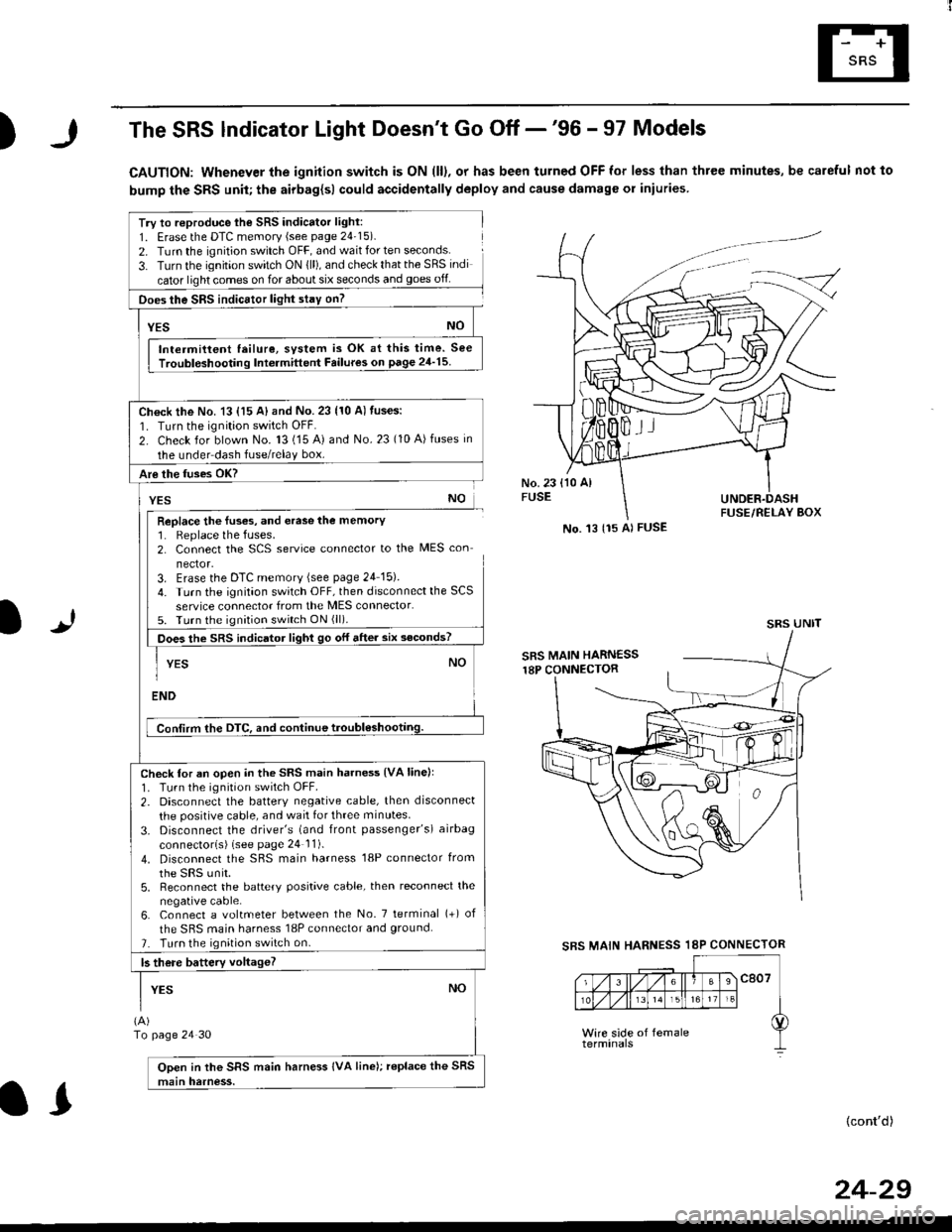
)The SRS lndicator Light Doesn't Go Off -'96 - 97 Models
CAUTION: Whenever the ignition switch is ON (ll), or has been turned OFF for less than three minutes, be careful not to
bump the SRS unit; the airbag{sl could accidentally deploy and cause damage or iniuries
Try to reproduce lhe SRS indicator light:
1. Erase the DTC memory (see page 24'15).
2. Turn the ignition switch OFF, and wait for ten seconds.
3- Turn the ignition switch ON {ll), and check that the SRS indi
cator light comes on for about six seconds and goes off
Does the SRS indicEtor light stay on?
[*NO
Intermittent lailure, system is OK at this time. See
Troubloshooting Int6rmittent Failures on page 24'15
Ch€ck the No. 13 {15 A} and No. 23 (10 A) fuses:
1. Turn the ignition switch OFF.
2. Check for blown No. 13 (15 A) and No.23 (10 A)fuses in
the under dash fuse/relay box.
Are the fuses OK?
vEs No
Replace the luses, and erase the memory1. Replace the fuses.2. Connect the SCS service connector to the MES con
nector.3. Erase the DTC memory (see page 24 15).
4. Turn the ignitaon switch OFF, then disconnect the SCS
service connector from the MES connector.5. Turn the ignition switch ON (ll).
Does the sRS indicato, tigt t go or "ne. "ii--JJl
-I YEs NO1
ENDi
Conlirm the DTC, and continue troubl6shootilg.
Check for an open in the SRS main harness {VA linell'1. Tu.n the ignition switch OFF.
2. Disconnect the battery negative cable, then disconnect
the positive cable, and wait for three minutes.
3. Disconnect the driver's (and front passenger's) airbag
connectorls) (see page 24 11).
4. Disconnect the SBS main harness '18P connector from
the sRS unir.5, Reconnect the battery positive cable, then reconnect the
negative cable.6. Connect a voltmeter between the No. 7 tetminal (+) of
the SRS main harness 18P connector and ground.
7. Turn the ignition switch on.
b there battery voltageT
YESNO
(A)
To page 24 30
Open in the SRS main harness IVA line); replace the SRS
main harness.
l.J
SBS MAIN
(cont'd)
No. 't3 {15 Al FUSE
SRS UNIT
HARNESS 18P CONNECTOR
II
24-29
Page 1772 of 2189
Troubleshooting
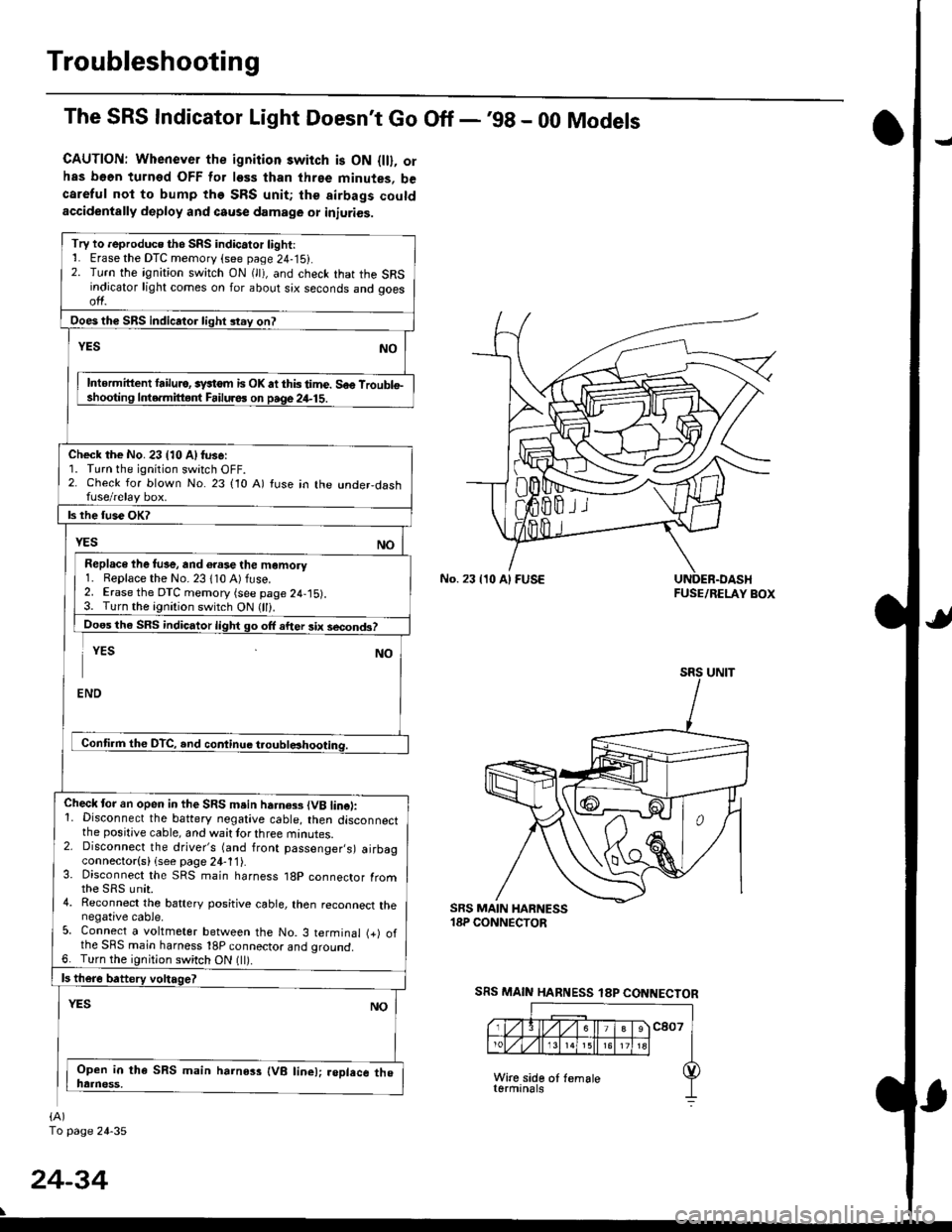
The SRS Indicator Light Doesn't Go Off -'98 - 00 Models
CAUTION: Whenever the ignition switch is ON {ll}, orhas b66n turned OFF for less than three minutes, becareful not to bump the SRS unit; the airbags coutdaccidentally deploy and cause damage or iniuries.
No. 23 {10 Al FUSEFUSE/RELAY BOX
SRS MAIN HARNESS 18P CONNECTOR
Try to reproduce the SRS indic.tor light:1. Erase the DTC memory (see page 24-15).2. Turn the ignition switch ON (lt), and check that the SRSindicator light comes on for about six seconds and ooesol1.
Intormittent lailulo, systom is OK atthistime. Soo Troublel. o.mittgnl Failuros on paqe24-15.
Check the No. 23 (10 Alfuse:1. Turn the ignition switch OFF.2. Check for blown No. 23 (10 A) tuse in the under,dashfuse/relay box.
Replace ihe fus€, and 6.ase the momory1. Replace the No. 23 110 A) fuse.2. Erase the DTC memory (see page 24,15).3. Turn the ignition switch ON (ll).
Doos the SRS indicator light go off after 3ix second3?
Check tor an open in the SRS msin harness {VB lincl:1. Disconnect the battery negative cable, then disconnectthe positive cable, and wait tor three minutes.2. Disconnect the driver's (and front passenger,s) airbagconnector(s) (see page 24-11).3. Disconnect the SRS main harness 18p connector Iromthe sRs unit.4. Reconnect the battery positive cable, then reconnect thenegative cable.5. Connect a voltmeter between the No. 3 terminal (+) ofthe SRS main harness 18P connector ano qrouno.6. Turn the ignition switch ON {ll).
(A)
To page 24-35
24-34