Page 1652 of 2189
lnterior Lights
Component Location Index
SPOTLIGHTSTest, page 23'184
CEILING LIGHTTest, page 23-183FRONT PASSENGER'SDOOR SWITCH
DRIVER'S DOOR
RIGHT REAR DOOR SWITCH
TRUNK LIGHT lcoupe/Sedan)Test, page 23-184
TRUNK LATCH{Coupe/Sedan)HATCH BACK LATCH SWTTCH lHatch bec(l
LEFT REAR DOOR SWITCH
23-1A2
Page 1653 of 2189
Circuit Diagram (Without Spotlightsl
BLUiBLK
I
I
l,**
I
l3g"
| ,J.,
ll
ISLUlBLK
A
Jiuir,
l[3Fff' Iflri:B::, ]
BLK
I
G601. G76l HalchbackG601 CoupeiSedan
3.4W . USA . Canada ProdLrced
5W W lhoui moonrool
q-
LT GRN/ RED LT GRN/RED
AA
Y;'.'; Y,"^t'
13fi?s" 13fi?'1"
|
3;::" B::::r".
1,3,;;:'
8::':tl"l
.Ll
GRNiRED
DOORSWTCH
FRONTPASSENGERS
folosed : Door open )(Open ' Door cosed -l
UNDEF HOOD FUSE]FELAY BOX
ON OFF
|l Fr+
| -r--
l:'iil:
LT GFN/REO
23-18�3
Page 1657 of 2189
Stereo Sound System
Component Location Index
SRS components are located in this area. Review the SRS component locations, precautions. and procedures in the SRS
section (24) before performing repairs or service.
'96 - 98 models
AUDIO UNIT(STEFEO RADIO TUNERIBeplacement, page 23 189Terminals, page 23-190
ANTENNA MASTReplacement, page 23 193
RIGHT TWEETERReplacement, Page 23 191
LEFT TWEETERReplacement, Page 23 191
ANTENNA LEAD
LEFT FRONT SPEAKER
Replacement, Page 23'191
SUB
RIGHT FRONT SPEAKERReplacement, page 23'191
ANTENNALEAD
CASSETTE PLAYER
Replacement, Page 23-189REAR SPEAKERSReplacement, page 23- 19'l
(cont'd)
23-147
q-
Page 1658 of 2189
Stereo Sound System
Component Location Index {cont'd)
SRS components are located ln this area. Review the SRS component locations, precautions, and orocedures in the sRSsection (24) before perlorming repairs or service.
'99 - 00 models
AUDIO UNITFeplacement, page 23-189Terminals, page 23-190
ANTENNA MAST (Coupe/Hatchbeck)Replacement, page 23,193RIGHT TWEETERReplacement, p6ge 23-191
LEFT TWEETERReplacement, page 23-191
ANTENNA LEAD
LEFT FRONTReplacement, page 23-191
RIGHT FRONT SPEAKERReplacernent, page 23-191
WINDOW ANTENNA {SedanlWire Test, page 23 192Wire Repair, page 23-192
SUB
I.TAO
REAR SPEAKERSReplacemont, page 23-191
23-1AA
Page 1661 of 2189

Removal
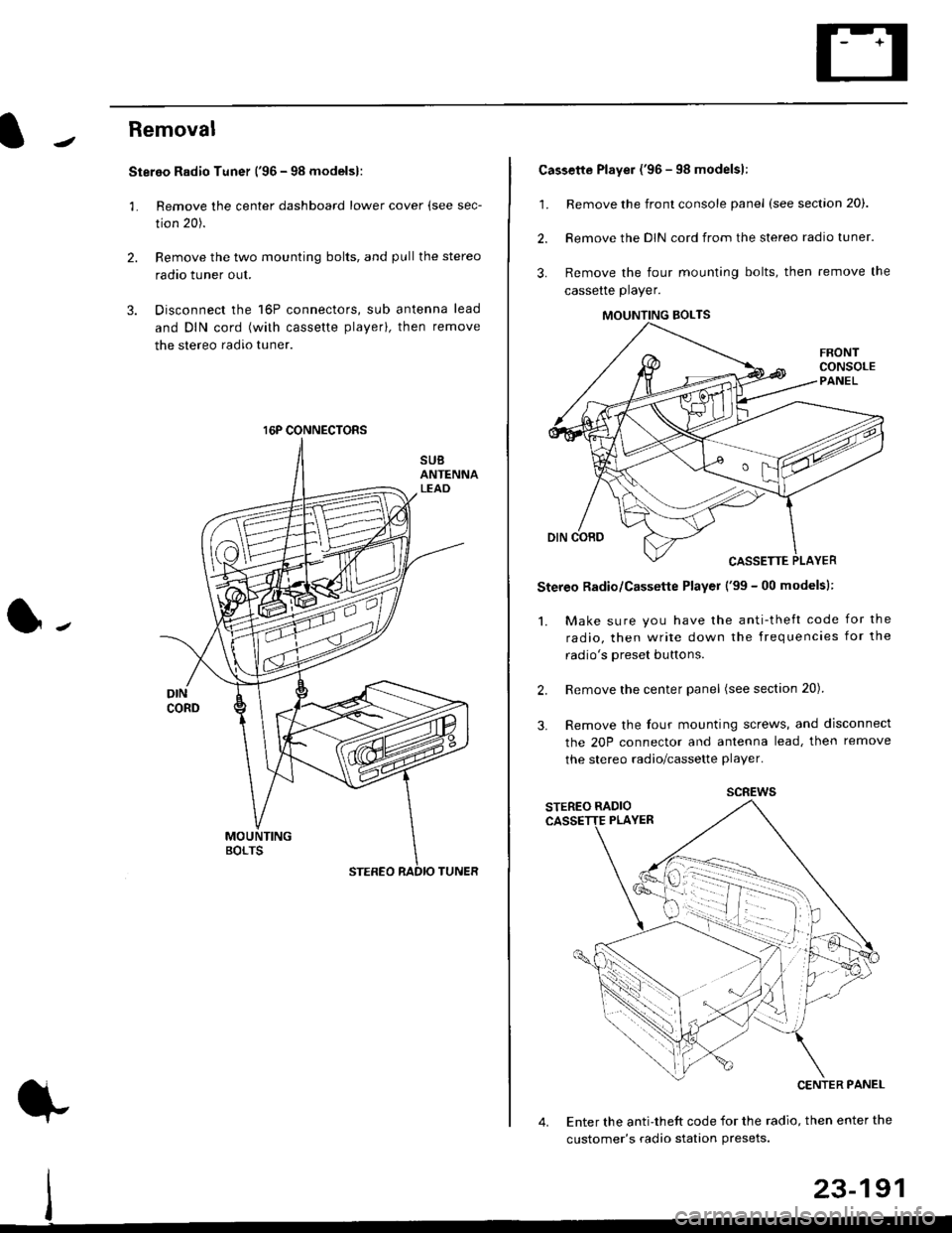
Stereo Radio Tuner ('96 - 98 modelsl:
3.
1.
2.
Remove the center dashboard lower cover (see sec-
tion 20).
Remove the two mounting bolts, and pullthe stereo
radao tuner out.
Disconnect the 16P connectors, sub antenna lead
and DIN cord (with cassette playerl, then remove
the stereo radio tuner.
16P CONNECTORS
1.
2.
Cassette Player ('96 - 98 modelsl:
Remove the front console panel (see section 20).
Remove the DIN cord from the stereo radio tuner.
Remove the four mounting bolts, then remove the
cassette player.
Stereo Radio/Cassette Player ('99 - 00 modelsl:
1. Make sure you have the anti-theft code for the
radio, then write down the frequencies for the
radio's oreset buttons.
Remove the center panel (see section 20).
Remove the four mounting screws, and disconnect
the 20P connector and antenna lead, then remove
the stereo radio/cassette player.
2.
3.
MOUNTING BOLTS
scREws
Enter the anti-theft code for the radio, then enter the
customer's radio station Presets.
23-191
Page 1662 of 2189

Stereo Sound System
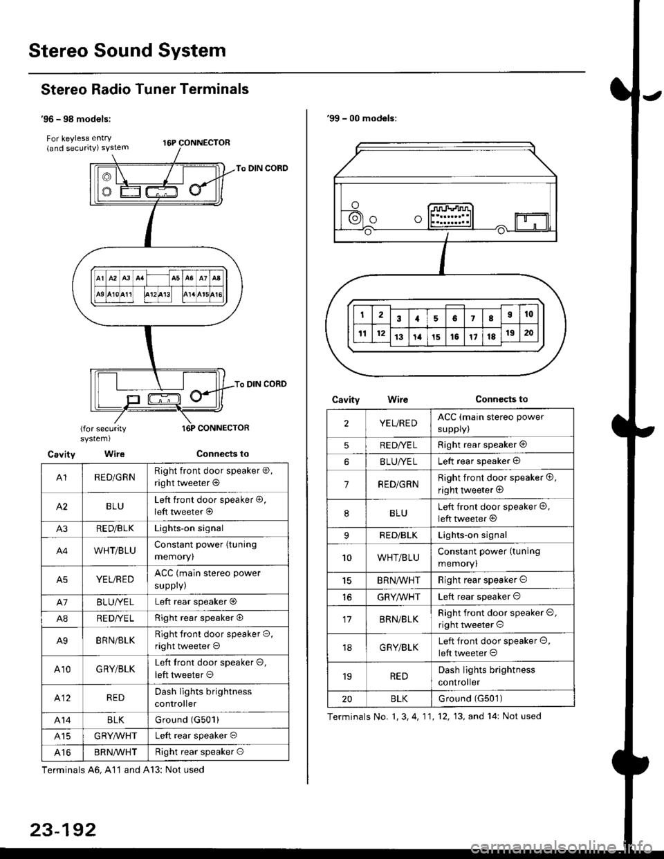
Stereo Radio Tuner Terminals
'96 - 98 models:
For keyless entry . t6p coNNEcroR(and securrty) syslem
To DIN CORD
To DIN CORD
(for securitysystem)
Cavity Wire
A1RED/GRNRight front door speaker o,
right tweeter @
BLULeft front door speaker @,
left tweeter @
A3RE D/B LKLights-on signal
A4WHT/BLUConstant power (tuning
memoryl
A5YEL/REDACC (main stereo power
suppry)
A7BLUI/ELLeft rear speaker O
A8RE DI/E LRight rear speaker O
A9BRN/BLKRight front door speaker O,
right tweeter o
A10GRY/BLKLeft tront door speaker O,
left tweeter O
412REDDash lights brightness
controller
A14BLKGround (G501)
415GRYMHTLeft rear speaker O
Al6BR N/VVHTRight rear speaker O
Terminals A6, A11 and A13: Not used
23-192
'99 - 00 models:
CsvityConnccts toWire
2YEL/REDACC (main stereo power
suppry)
5RE DI/E LRight rear speaker @
BLUI/ELLeft rear speaker @
7RED/GRNRight front door speaker @,
right tweeter @
8BLULeft front door speaker @,
left tweeter @
9RED/BLKLights-on signal
10WHT/BLUConstant power (tuning
memory)
15BRN,ryVHTRight rear speaker O
GRYMHTLeft rear speaker O
17BRN/BLKRight front door speaker O,
right tweeter O
18G RY/BLKLeft front door speaker O,
left tweeter O
'19REDDash lights brightness
controller
20BLKurouno t(l5u t,
Terminals No. 1, 3, 4, 11,12, 13, and 14: Not used
Page 1663 of 2189
Speaker Replacement
Front speaker:
1. Remove the speaker cover.
2. Remove the three screws from the speaker.
3. Disconnect the 2P connector, and remove the door
speaker.
Tweeter:
1. Remove the door panel (see section 20).
2. Disconnect the 2P connector from the tweeter.
3. Remove the mirror garnish.
4, Remove the two screws, then remove the wveeter.
FRONT SPEAKER
TWEETER(}-
23-193
Rear speaker:
1. Remove the rear side shelf or rear shelf (see section
20t.
2. Disconnect the 2P connector from the speaker.
3. Remove the four screws, then remove the speaker.
Hatchback:
Coupe/Sedan:
2P CONNECTOF
2P CONNECTOR
REAR
Page 1667 of 2189
Circuit Diagram: '96 - 97 models
HORNRELAY
WHT/GRN
I(H)HoRN
Y
IBLU/REO
I
I
IBtK
I
t-l
G40lG1A2
BATTERY
l-
23-197
Horn Test: '96 - 97 models
1. Remove the front bumper (see section 20).
2. Disconnect the 2P connector from the horn.
Remove the horn.
Test the horn by connecting battery power to one
terminal and grounding the other, lf the horn fails to
sound, replace it.
3.
LOW HORN