Page 822 of 2189
Secondary Valve Body
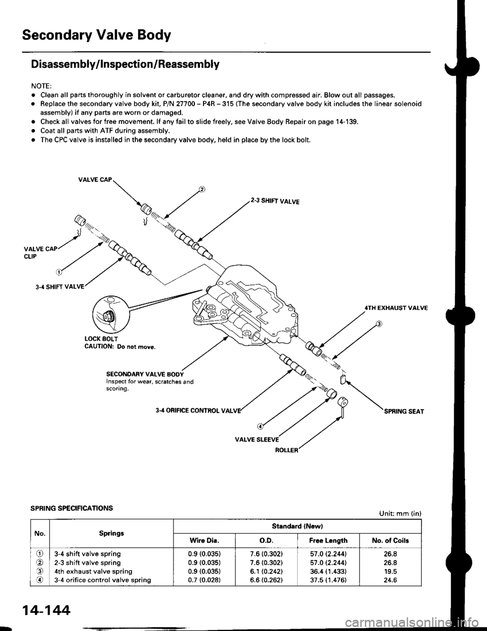
Disassembly/lnspection/Reassembly
NOTE:
. Cleanall parts thoroughly in solvent or carburetor cleaner. and drywith compressed air, Blowoutall passages.
. Replace the secondary valve body kit. P/N 27700 - P4R - 315 (The secondary valve body kit includes the linear solenoid
assembly) if any parts are worn or damaged.
. Checkall valves for free movement. lf anyfailto slide freely, seeValveBody Repairon page 14-139,
. Coat all parts with ATF during assembly.
. The CPC valve is installed in the secondary valve body, held in place by the lock bolt.
2.3 SHIFT VALVE
3.4 SHIFT VAL
.TH EXHAUST VALVE
LOCK BOLTCAUTION: Do not move.
SECONDARY VALVE BODYInspect for wear, scratches 6ndscoring.
3-'l ORIFICE CONTROL VAL
VALVE
SPRING SPECIFICATIONSUnit: mm (in)
No.SpringsStandard {New)
Wire Dia.o.D.Free LongthNo. of Coils
ora,.n
3-4 shift valve spring
2-3 sh ift valve spring
4th exhaust valve spring
3-4 orifice control valve spring
0.910.035)
0.9 {0.035)
0.9 {0.035)
0.7 {0.028)
7.6 (0.302)
7.6 (0.302)
6.1 10.2421
6.6 (0.262)
57 .O 12.2441
57 .O 12.2441
36.4 (1.433)
37.5 (1.476)
26.8
26.8
24.6
14-144
Page 823 of 2189
Regulator Valve Body
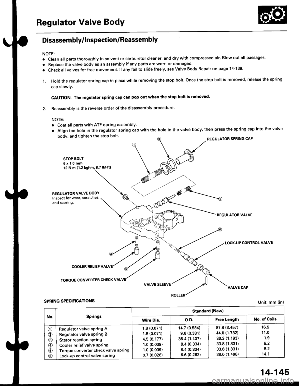
Disassembly/lnspection/Reassembly
NOTE:
. cleanall parts thoroughly in solvent or carburetor cleaner, and drywith compressed air. Blowoutall passages
. Replace the valve body as an assembly if any parts are worn or damaged.
. check allvalves for free movement. lf anyfail toslidetreely, see valve Body Repairon page 1+139.
1. Hold the regulator spring cap in place while removing the stop bolt. once the stop bolt is removed. release the spring
cap slowly.
CAUTION: The regulator 3pring cap can pop out when the stop boh is removod'
2. Reassembly is the reverse order ofths disassembly procedure.
NOTE:
o Coat all parts with ATF during assembly.
. Align the hole in the regulator spring cap with the hole in the valve body, then press the spring cap into the valve
body, and tighten the stop bolt.
STOP BOLT6x1.0mm12 N.m 11.28.7 tbf.lrl
^/^'ou*'oRsPRrNGcAP
*N@
REGULATOR VALVE
\=f -.-*
*fi /F { a-tLocK.uPcoNrRoLvALVE
cooLERRELlEFvALVr"r?
ry
roRouE coNvERrER cHEcKv ^LvE//
v ^r* "r**::f vi{LvE cAp
SPRING SPECIFICANONS
REGULATOR VALVE BODY
Inspect lor wear, scratches
and scorlng.
Unit: mm (in)
No,Springe
Standard (Now)
Wire Dia.o.D.Free LengrthNo. of Coils
o
o
@
@
@
Regulator valve sPring A
Regulator valve spring B
Stator reaction spring
Cooler relief valve spring
Torque converter check valve spring
Lock-up control valve sPring
1.8 {0.07'�r)
1.8 (0.071)
4.5 (0.177)
1.0 (0.039)
1.0 (0.039)
0.7 (0.028)
'r4.7 (0.584)
9.6 (0.381)
35.4 (1.407)
8.4 {0.334)
8.4 {0.334}
6.6 {0.262}
87.8 (3.457)
44.0 (1.732)
30.3 (1.193)
33.8 (1.331)
33.811.3311
38.0 {1.4961
11.0
1.9
8.2
a.2't 4.1
14-145
Page 825 of 2189
Lock-up Valve BodY
Disassembly/lnspection/Reassembly
NOTE:
. Clean all pans thoroughly in solvent or carburetor cleaner' and dry with compressed air' Blow out all passages'
a Replace the valve body as an assembly if any parts are worn or d€maged'
. Checkall valves for free movement ttanytaitio stlae freely' see Valve Body Repairon page 14-'139'
. Coat all parts with ATF during assembly
LOCK.UP VALVE BODY
Inspect for wear, scratchesand sconng.
VALVE CAP
LOCK-UP TIMING VAL
SPRING SPECIFICATIONSUnit: mm (in)
73.1 t2.902J
ao.7 13.'17717.6 (0.302)
8.1 (0.319)Lock-up shift valve sPrang
Lock-up timing valve sPrlng
14-147
Page 911 of 2189
Troubleshooting Procedures
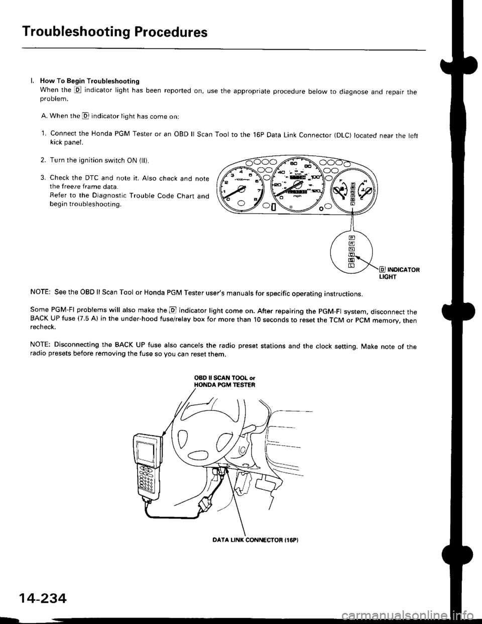
l. How To Begin Troubleshooting
When the E indicator light has been reported on, use the appropriate procedure below to diagnose and repatr theproDlem.
A. When the @ indicator light has come on:
l connect the Honda PGM Tester or an oBD ll Scan Tool to the 16P Data Link Connector (DLc) located near the leftkick panel.
Turn the ignition switch ON (ll).
Check the DTC and note it. Also check and notethe freeze frame data.
Refer to the Diagnostic Trouble Code Chart andbegin troubleshooting.
INOICATORLIGHT
NOTE: SeetheOBDll Scan Tool or Honda PGM Tester user's manuals for specific operating instructions.
Some PGM-FI problems will also make the E indicator light come on. After repairing the pGM-Fl system, disconnect theBACK UP fuse (7.5 Al in the under-hood fuse/relay box for more than l0 seconds to reset the TCM or PCM memory, rnenrecheck.
NOTE: Disconnecting the BACK UP fuse also cancels the radio preset stations and the clock setting. Make note of theradio presets before removing the fuse so you can reset them,
2.
3.
o0\e--loo
OATA LINK CONNECTOB I16P}
14-234
Page 912 of 2189
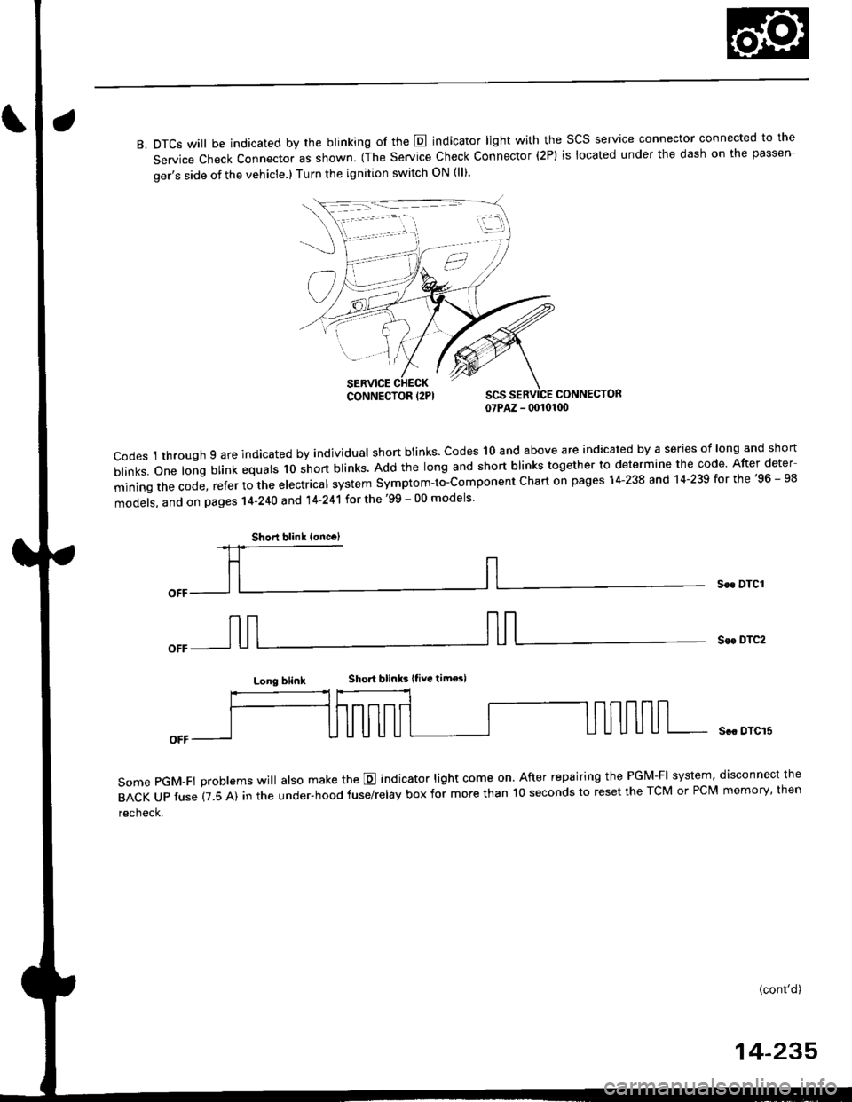
B. DTCS will be indicated by the blinking of the E indicator light with the SCS service connector connected to the
Service Check Connector as shown. (The Service Check Connector (2P) is located under the dash on the passen
ger's side of the vehicle.) Turn the ignition switch ON (ll).
CONNECTOR07PAZ - 00101(x)
codes 1 through 9 are indicated by individual shon btinks. codes 10 and above are indicated by a series of long and short
b|inks.one|ongblinkequa|sloshortb|inks.Addthe|ongandshortb|inkstogethertodeterminethecode.Afterdeter
miningthecode,refertothee|ectrica|systemsymptom-to-componentchartonpagesl4-238and14.239forthe,96_98
models, and on pages 14-240 and 14'241 for the '99 - 00 models
Soc DTCI
Sor DTC2
Long blinkShort blinks |tive tim€sl
some pGM-Ft problems wi
atso make the E indicator light come on. After repairing the PGM-FI system, disconnect the
BACKUPfuse(7.5A)intheUnder.hoodfuse/re|ayboxformorethanl0secondstoresettheTcMorPcMmemory,then
recheck.
Scc DTCI5
(cont'd)
14-235
iii:j
,,,/
CONNECTOR {2PI
Shorl blink (oncc)
Page 916 of 2189
lf the self-diagnostic E indicator light does not blink, perform an inspection according to the table below.
SymptomInspectionRef. page
E indicator light does not come on for two seconds after ignition switch
is first turn on (ll).14-262
E indicator light is on constantly (not blinking) whenever the ignition
switch is on (ll).14-264
NOTE:
. lf a customer described the symptom for code P1706 (6), it will be necessary to recreate the symptom by test driving,
then recheck the DTC.
. Sometime the E indicator light and the Malfunction Indicator lamp (MlL) may come on simultaneously. lf so, repair the
pGM-Fl system according to the DTc, then reset the memory by removing the BACK uP fuse in the under-hood
fuse/relay box for more than 10 seconds. Drive the vehicle for several minutes at a speed over 30 mph (50 km/h)' then
recheck the DTC.
14-239
Page 918 of 2189
lf the self-diagnostic E indicator light does not blink. perform an inspection according to the table below.
SYmPtom
IDI indicator light does not come on for two seconds after ignition switch
is first turned ON (ll).
lE1 indicator light is on constantly (not blinking) whenever the ignition
switch is ON { ll).
InspectionRef. page
14-284
14-290
NOTE:
. lf a customer described the symptom for code Pl706 (6), it will be necessary to recreate the symptom by test driving,
then recheck the DTC.
. iometimes, tfre E indicator light and the Malfunction Indicator lamp (MlL) may come on simultaneously lf so, repair
the PGM-Fl system accordrng to the DTC, then reset the memory by removing the BACK UP RADIO fuse in the under-
hood fuse/relay box for more than 10 seconds. Drive the car for several minutes at a speed over 30 mph {50 km/h)' then
recheck the DTC.
14-241
Page 919 of 2189
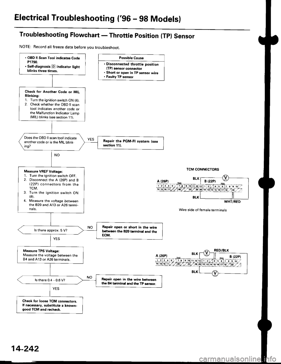
Electrical Troubleshooting ('96 - 98 Modelsl
Troubleshooting Flowchart - Throttle position (Tpl Sensor
Possible Cause
. Disconnected throftle position(TPl 3ensor connoctol. Short or open in TP sensor wire. Fauhy TP sensol
TCM CONNECTORS
Wire s;de of female terminals
. OBO ll Scan Tool indic.tes CodeP1790.. Self-diagnosis E indicator lightblinks three times.
Check lor Anothar Code or MILBlinking:1. Turn the ignition switch ON 1 ).2. Check whether the OBD ll scantool indicates another code orthe Malfunction Indicator Lamp(MlL) blinks (see secrion 11).
Does the OBD ll scan tool indicateanothercode oristhe MIL blink-ing?
Repair the PGM-FI systom (3eesection 111.
Measure VREF Voltage:1. Turn the ignition switch OFF.2. Disconnect the A (26P) and B{22P} connectors lrom theTCM.3. Turn the ignition switch ON{fl).4. Measure the voltage bet\iveenthe 820 and A13 or 426 termi-nals,
Repair open or short in thc wireb,stween the Bao tcrminal rnd theECM.
ls lhere approx. 5 V?
Measure TPS Voltago:Measure the voltage between theB4 and A13 or 426 terminals.
Repail open in the wire tr€tweonthe Erl t6.minal ind the TP sen3o..ls there 0.4 - 0.6 V?
Check for loose TCM connectors.lf necessary, substitute a known-good TCM and r6check.
NOTE: Record all freeze data before you troubleshoot.
BLK
WHT/RED
A {26P1