Page 752 of 2189

Electrical Troubleshooting ('96 - 98 Models)
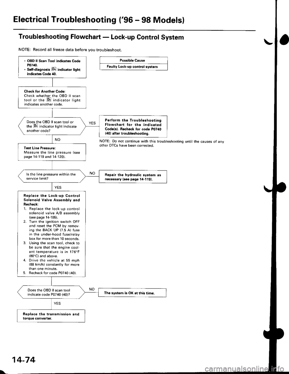
Troubleshooting Flowchart - Lock-up Control System
NOTE: Record all freeze data before vou troubleshoot.
Possible Cause
Faulty Lock-up cont.ol system
NOTE: Do not continue with this troublesnoonnoother DTCS have been corrected.until the causes of any
. OBD ll Sc6n Tool indicatG Codem7{0.. Self-diagnosis E indicator lightindicates Code 40.
Check tor Another Code:Check whether the OBD ll scantool or the E indicato, lightindicates another code.
Perform lhe Troublo3hooiingFlowchart tor the indicatedCode(s). Recheck for cod. P07il0lilol aftor iroubl€3hooting.
Does the OBD ll scan tool orthe E indicator light indicateanother code?
Tast Line Pressure:Measure the line pressure (seepage 14-119 and 14-120).
Repair tho hydreulic aystem a3necessary {3ee page 14-119).
Replace the Lock-up ControlSolenoid Valve Assembly andR6check;1. Beplace the lock up controlsolenoid valve Ay'B assembly(see page 14-105).2. Turn the ignitaon switch OFFand reset the PCM by removing the BACK UP (7.5 A) fusein the underhood fuse/relaybox for more than 10 seconds,3. Using the scan tool, check tobe sure that the engine coolant temperature is in 176'F(80'C) and above.4. Drive the vehicle at 55 mph(88 km/h) constantly for morethan one minute.5. Recheck for code P0740 (40).
Does the OBD ll scan toolindicate code P0740 {40)?The systom k OK at this time.
l'.
14-74
Page 754 of 2189

Electrical Troubleshooting ('96 - 98 Models)
Troubleshooting Flowchart - E Indicator Light Does Not Gome On
PCM CONNECTOR A I32PI
Wire side of female terminals
Tha E indicator light does nolcome on when the ignition swhchis first turned ON (lll. {lt shouldcome on tol about two s€conds.l
Chock the SeJvico Check Connec-tor:Make sure the special tool (SCS
Seryice Conneclor) is not connect-ed to the service check connector.
ls the special tool (SCS ServiceConnector) connected to the service check connector?
Disconnect the special tool tromthc sarvice check connoctor androcheck.
Check th6 E indicator Light:Shift to lD.l oosition.
Check tor loose PCM connecto6.ll nece3sary, sub.titute a known-good FCM and r.chock.
Check the Ground Circuit:'1. Turn the ignition switch OFF.2. Disconnecr the A {32P}connec-tor lrom the PCM.3. Check for continuity betweenthe A9 terminal and bodyground and the A22 terminaland body ground.
Repair op6n in tho wirgsbetween tho A9 ot M2 tormi-nals and G101.Rcpair poor glound {G101).
To page 14-77
l.
14-76
Page 756 of 2189
Electrical Troubleshooting ('96 - 98 Models)
Th6 E indicstor light is on con-st.ntly {not blinkingl wheneveithe ignition switch is ON lll).
Measure 04 IND Voltage:1. Turn the ignition switch OFF.2. Disconnect the B 125P) connec-tor from the PCM.3. Turn the ignition switch ON (ll).
4. Measure the voltage betweenthe 813 terminal and bodyground,
Repair 3hort to pow€. in the wirobetween the 813 terminal endthc gauge asiombly.
Meaiure ATP Dil Voltage:1. Turn the ignition switch OFF.2. Connect the I (25P) connectorto the PCM.3. Turn the ignition switch ON (ll).4. Shiftto any position otherthan
5. Measure the voltage betweenthe 824 terminal and bodygrou nd.
Check for a short to ground on thowir6. It wire i3 OK, .eplac6 the A/Tgoar po3ition indbator,
Troubleshooting Flowchart - E Indicator Light On Constantly
a!
PCM CONNECTOR B (25P)
Wire side of lemale terminals
l.
14-7A
Page 760 of 2189

Electrical Troubleshooting ('99 - 00 Models)
Troubleshooting Flowchart - Lock-up Control Solenoid Valve B
NOTE| Record allfreeze data before you troubleshoot.
Possibla Cause
. Oisconnected lock-uD controlsolenoid velve A/B assemblyconnector. Short or open in lock-up controlsolenoid valv€ B wire. Faulty lock-up control solenoidvalve B' Open in VB SOL wirercM CONNECTORS
To page 14-83
' OBD ll Scan Tool indic.tes CodeP1758.. Self-diagnosis E indicatorlight blinks twice.
Chack for a Short to Power:1. Turn the ignition switch OFF.2. Disconnect the I (25P) and D(16P) connectors from thePCM.3. lurn the ignition switch ON (ll).4. Measure the voltage betweenthe D3 and 820 ot 822 tetmi-nals,
Repair short to power in the wirebetween the D3 terminal and thelock-up contlol solenoid valve B.
Measure Lock-up Control Sole-noid Vdlve I R8i3tance:1. Turn the ignition switch OFF.2, Measure the resistancebetween the D3 and 820 or822 terminals.
ls the resistance 12 - 25 O?
Measure VB SOL Voltago:1. Turn the ignition switch ON lll).2. Measure the voltage betweenthe D5 and 820 or 822 termi-nals.
Check for blown No. 15 {7.5 Alfus€ in the under-dash luse/releybox. It the fuse is OK, repair openin the wir6 between th6 DS terminal and the under-dash fuse/rebyoox,
ls there battery voltage?
Chock for loose te.minal fit in thePCM connectors. It necessary,substitute a known-good PCMend recheck.
B t2sP) ll D t15P)
Wire side ol female terminals
I {2sPt ll D (16Pt
B (25P1 D t16Pt
\
14-82
Page 761 of 2189

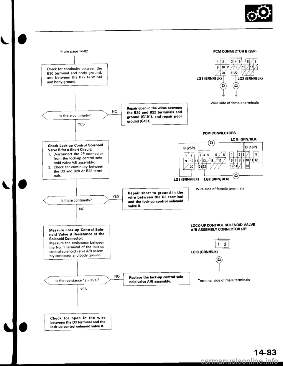
From page 14-82
Check for continuitY between the
820 terminal and body ground,
and between the 822 terminal
and body ground
Repair open in the wires between
the 820 and 822 terminals and
ground |G101), and repair Poolground (G1011.
Check Lock-up Control Solenoid
Valve B lor a Short Cilcuit:
1. Disconnect the 2P connector
from the lock_uP control sole-
noid vaive A/B assemblY.
2. Check for continuity between
the D3 and 820 or 822 termi
nals.
Rep.ir short to ground in lho
wire between lhe D3 terminal
and the lock-up contlol solenoid
valve B.
Measure Lock-up Control Sol6'
noid Valve B Resistance at the
Sol6noid Conn€ctor:Measure the resistance between
the No. 1 terminal of the lock uP
control solenoid valve A'lB assem_
bly connector and body ground-
Repl.ce the lock-up control 3olc
noid valve A/B a$emblY.ls the resistance 12 - 25 0?
Ch6ck {or open in the wire
between the D3 terminal dnd ihe
lock-up control sol€noid valve B.
PCM CONNECTOR B (25PI
LG1 (BRN/BLK)
2351 6I
l011/15
LG2
oo
(BRN/BLKI
Wire side of female terminals
Wire side of female terminals
LOCK.UP CONTROL SOLENOID VALVE
A/B ASSEMBLY CONNECTOR (2PI
t;T�Jllt z!]4
LC B (GRN/BLKI It(o)
YI
Terminal side of male termrnals
B (25P1 - llo t16Pt
14-83
Page 766 of 2189
![HONDA CIVIC 1997 6.G Workshop Manual Electrical Troubleshooting (gg - 00 Models)
Troubleshooting Flowchart - A/T Gear position Switch Open {cont,d)
PCM CONNECTORS
B l2sPlD {16P)
124156I
91011)./t5l/11189112
zo ztzzl l//l hsr),41
f ]_c;l HONDA CIVIC 1997 6.G Workshop Manual Electrical Troubleshooting (gg - 00 Models)
Troubleshooting Flowchart - A/T Gear position Switch Open {cont,d)
PCM CONNECTORS
B l2sPlD {16P)
124156I
91011)./t5l/11189112
zo ztzzl l//l hsr),41
f ]_c;l](/manual-img/13/6068/w960_6068-765.png)
Electrical Troubleshooting ('gg - 00 Models)
Troubleshooting Flowchart - A/T Gear position Switch Open {cont,d)
PCM CONNECTORS
B l2sPlD {16P)
124156I
91011)./t5l/11189112
zo ztzzl l//l hsr),41
f ]_c;l
j r-cz tgaNlelxr -ATP D4
Wire side of lemale terminals
(YEL}LGl {BRN/BI.KI
I.G1 IERN/BLKI
B (25P1
LGl IBRN/BLKI
D {16P}
From page 14-87
Moalure ATP 04 Vohago:1. Shift to pll position.2. Measure the voltage betweenthe Dg and 820 or 822 terminals.
Repair opon in the wire betweonthe lrg terminal and the A/T goatposhion switch.
Measure ATP D3 Vohage:1. Shift to l& position.2. Measure the voltage betweenthe D8 and 820 or 822 termi-nats.
Reprir opcn in the wirc b?twoenthe D8 terminrl and tho A/T goarDosition twitch.
Mersurc ATP 2 Voltage:1. Shift to E position.2. Measure the voltage betweenthe Dl4 and 820 or 822 termi-nals,
Reprir opon in the wire betweontho Dl4 te.minal rnd the A/Tgo.r position switch.
Ch6ck tor loose terminal tit in thePCM connectors. ll necossery,subslitute . known-good pCM
and recheck.
LG2IBRN/BLKI
I25l l6l/8
91011)/Itsln78912
ATP 2 IBLUI
t..
14-88
Page 768 of 2189

Electrical Troubleshooting ('gg - 00 Models)
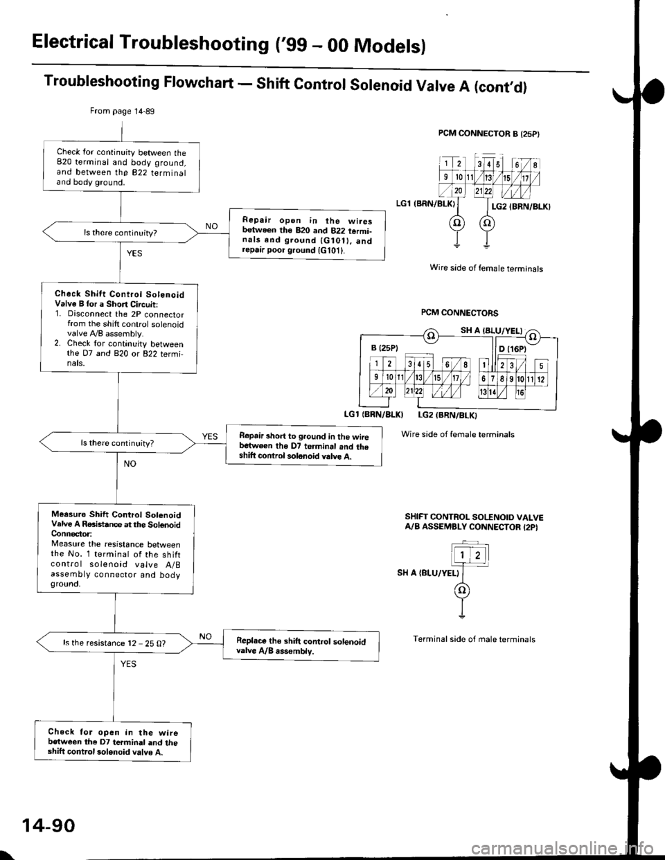
Troubleshooting Flowchart - Shift Control Solenoid Valve A (cont,O)
PCM CONNECTOR B {25P}
LGl (BRN/BLKI
Wire side of female terminals
rcM CONNECTORS
LGl {BBN/BLKI LG2 (BRN/BLKI
Wire side of female terminals
SHIFT CONTROL SO|'INOID VALVEA/B ASSEMBLY CONNECTOR I2PI
SH A {BLU/YELI
From page 14-89
Check lor continuity between the820 terminal and body ground,and between the 822 terminaland body ground.
Repair open in ihe wiresbetween th€ 820 and 822 termi-nals end ground {G10ll. andrepa,r poor ground {G101}.
Check Shitt Control SolenoidValve B for a Short Circuit:1. Disconnect the 2P connectorfrom the shilt control solenoidvalve A,/B assembly.2. Check lor continuity betweenthe D7 and 820 or 822 termi,nals.
R€pair short to ground in the wiiebartwe€n the D7 te.minal and theshift control solonoid valve A.
ls there continuity?
Meesuro Shift Control SolenoidValve A RGistance at the SolenoidConnector:Measure the resistance betweenthe No. 1 terminal of the shiftcontro I solenoid valve A/Bassembty connector and bodygrounct,
Repl.ce tho shift control solenoidvalve A/B rss€mblv.ls the resistance 12 25 O?
Check for open in the wirebetween the D7 termindl and theshift control 3olonoid valve A.
B t25Pt llD t16Pt
\
14-90
Page 769 of 2189

Troubleshooting Flowchart - Shift ControtSolenoid Valve B
NOTE: Record all freeze data before you troubleshoot.
Possiblg Cause
. Disconnectgd ihilt control
solenoid valve A/B conneciotr Short or oDen in shift conlrol
3olgnoid vrlve B wito. Faulty 3hift control solenoid
velve B. Op€n in VB SOL wirercM CONNECTORS
LGlIBRN/BLKI LG2IBRN/BLK)
Wire side of {emale terminals
LGi (BRi|/BLKILG2 IBRN/8LK)
To page 14-92
(cont'd)
14-91
. OBD ll Scan Tool indic.l6 Code
P0758.' Self-diagnosb El indicator light
blinks eighl tim6.
Check tor a Shortto Power:
1. Turn the ignition switch OFF
2. Disconnect the B (25P) and D(16P) connectors from the
PCM.3. Turn the ignition switch ON (lli.
4. Measure the voltage between
the D2 and 820 or 822 termi
nals,
Repaft 3hon to Powor in the wir€
b€tirvoon the D2 termin.l and the
3hift control solenoid valve B.
M€asure Shift Control SolenoidValve B R6isttnce:1. Turn the ignition switch OFF
2. Measure the resistance
between the D2 and 820 or
822 terminals.
ls the resistance 12 - 25 O?
Me.sure VB SOL Vohage:1. Turn the ignition switch ON (ll).
2. Measure the voltage betweenthe D5 and 820 or 822 termi'
nars.
Check lol blown No 15 {7.5 Al
fuse in the under-d.sh luae/rolav
box. ll the fuse is OK, repair open
in ihe wire between tho D5 ter-
minal and the under'dash fus€/relav box.
ls there battery voltage?
Check for loo3e terminal fit in the
PCM connectols. lf necossarY,
substitute a known_good PCM
and rocheck,
B (25Pt - I lD {16P)
B {25P1 D (t6Pl