Page 127 of 224

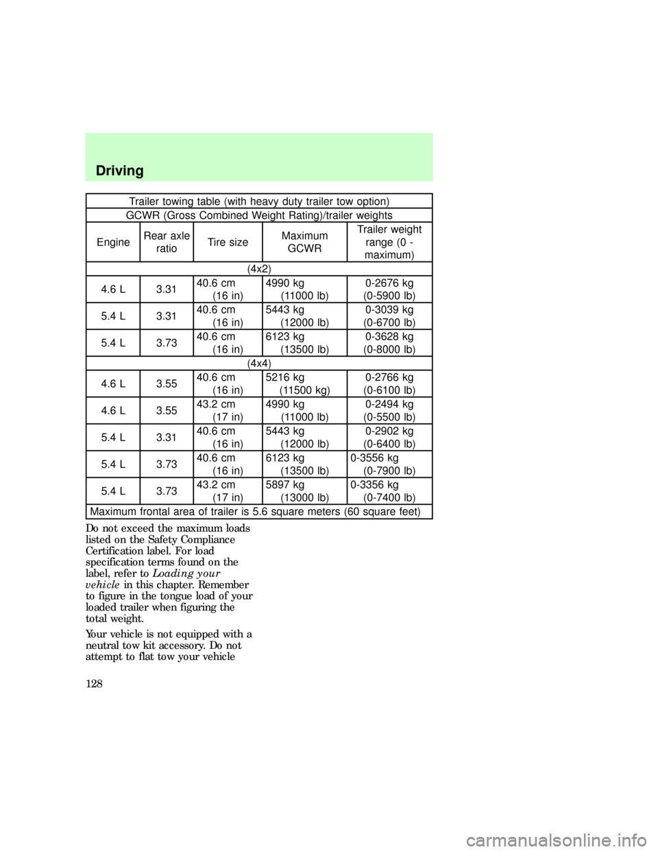
Trailer towing table (with heavy duty trailer tow option)
GCWR (Gross Combined Weight Rating)/trailer weights
EngineRear axle
ratioTire sizeMaximum
GCWRTrailer weight
range (0 -
maximum)
(4x2)
4.6 L 3.3140.6 cm
(16 in)4990 kg
(11000 lb)0-2676 kg
(0-5900 lb)
5.4 L 3.3140.6 cm
(16 in)5443 kg
(12000 lb)0-3039 kg
(0-6700 lb)
5.4 L 3.7340.6 cm
(16 in)6123 kg
(13500 lb)0-3628 kg
(0-8000 lb)
(4x4)
4.6 L 3.5540.6 cm
(16 in)5216 kg
(11500 kg)0-2766 kg
(0-6100 lb)
4.6 L 3.5543.2 cm
(17 in)4990 kg
(11000 lb)0-2494 kg
(0-5500 lb)
5.4 L 3.3140.6 cm
(16 in)5443 kg
(12000 lb)0-2902 kg
(0-6400 lb)
5.4 L 3.7340.6 cm
(16 in)6123 kg
(13500 lb)0-3556 kg
(0-7900 lb)
5.4 L 3.7343.2 cm
(17 in)5897 kg
(13000 lb)0-3356 kg
(0-7400 lb)
Maximum frontal area of trailer is 5.6 square meters (60 square feet)
Do not exceed the maximum loads
listed on the Safety Compliance
Certification label. For load
specification terms found on the
label, refer toLoading your
vehiclein this chapter. Remember
to figure in the tongue load of your
loaded trailer when figuring the
total weight.
Your vehicle is not equipped with a
neutral tow kit accessory. Do not
attempt to flat tow your vehicle
Driving
128
Page 128 of 224
with all of the vehicle wheels on
the ground.
Towing trailers beyond the
maximum recommended
gross trailer weight exceeds the
limit of the vehicle and could
result in engine damage,
transmission damage, structural
damage, loss of control and
personal injury.
Preparing to tow
Use the proper equipment for
towing a trailer and make sure that
it is properly attached to your
vehicle. See your dealer or a
reliable trailer retailer if you
require assistance.
If your vehicle is not equipped
with the factory heavy duty trailer
tow option, auxiliary coolers are
recommended for the automatic
transmission system if you are
planning on:
²traveling farther than 80 km (50
miles)
²towing in hilly terrain
²towing frequently
Calculating trailer loads
To determine the amount of weight
that your vehicle can carry:
²Obtain ratings from the Safety
Compliance Certification label
and the trailer towing
specifications in this chapter.
exd_preparing_tow
exd_calculating_load
Driving
129
Page 133 of 224
HAZARD LIGHTS CONTROL
Use only in an emergency to warn
traffic of vehicle breakdown,
approaching danger, etc. Depress
to activate all indicators
simultaneously. Depress again to
switch off. The warning lights can
be operated when the ignition is
off.
FUEL PUMP SHUT-OFF SWITCH
If the engine cranks but does not
start after a collision, the fuel
pump shut±off switch may have
been activated. The shut±off
switch is a device intended to stop
the electric fuel pump when your
vehicle has been involved in a
substantial jolt.com_hazard_switch.01
exd_fuel_shut-off
Roadside emergencies
134
Page 136 of 224
Power network box
Slot number Fuse
amperage
ratingCircuits protected
1 20 amp Trailer tow backup & tail lamps
2 10 amp Airbag diagnostic monitor
3 30 amp Power locks
4 15 amp Air suspension
5 20 amp Horn
6 30 amp Engine minifuse box fuses #3 and #5
7 15 amp Park and tail lamps
8 30 amp Headlamps
9 15 amp Fog lamps and DRL
10 25 amp Auxiliary instrument panel (I/P) power
point
11 25 amp Auxiliary console power point
12 10 amp Rear wiper
29
6
5
4
3
2
1 28
27
26
25
24
2319
18
17
16
15
14
13
22
21
20
12
1197531
12108642
exd_power_network_box
Roadside emergencies
137
Page 137 of 224
Slot number Fuse
amperage
ratingCircuits protected
13 30 amp Auxiliary blower
14 60 amp Four wheel anti-lock brake system
(4WABS)
15 50 amp Air suspension compressor
16 40 amp Trailer tow battery charge, engine
minifuse box fuse #2, engine minifuse
box fuse #4
17 30 amp Four-wheel drive (4WD) transfer case
motor and clutch
18 30 amp Driver power seat
19 20 amp Fuel pump
20 50 amp Junction box ignition switched feed
21 50 amp Junction box ignition switched feed
22 50 amp Junction box battery feed
23 40 amp Front blower
24 30 amp Powertrain control module power
25 30 C.B. Windows
26 - not used
27 40 amp Heated backlite and mirrors
28 30 amp Trailer tow electric brake
29 30 amp Hybrid fan, moon roof, flip windows
Slot number Description
1 - not used
2 - PCM diode
Slot number Description
1 - Windshield wipers high/low speed
2 - Windshield wipers run/park
3 - Front washer pump relay
4 - Fuel pump relay
Roadside emergencies
138
Page 138 of 224
Slot number Fuse
amperage
ratingCircuits protected
5 - Horn relay
6 - PCM power relay
Engine mini fuse box
Slot number Fuse
amperage
ratingCircuits protected
1 5 amp Powertrain control module (PCM)
2 20 amp Trailer tow stop/turn lamps
3 10 amp Audio rear integrated control panel
(RICP), compact disc changer, radio
4 10 amp Running board lamps
5 20 amp Amplifier, subwoofer amplifier
6 - Not used
123456
exd_engine_mini_fuses
Roadside emergencies
139
Page 143 of 224

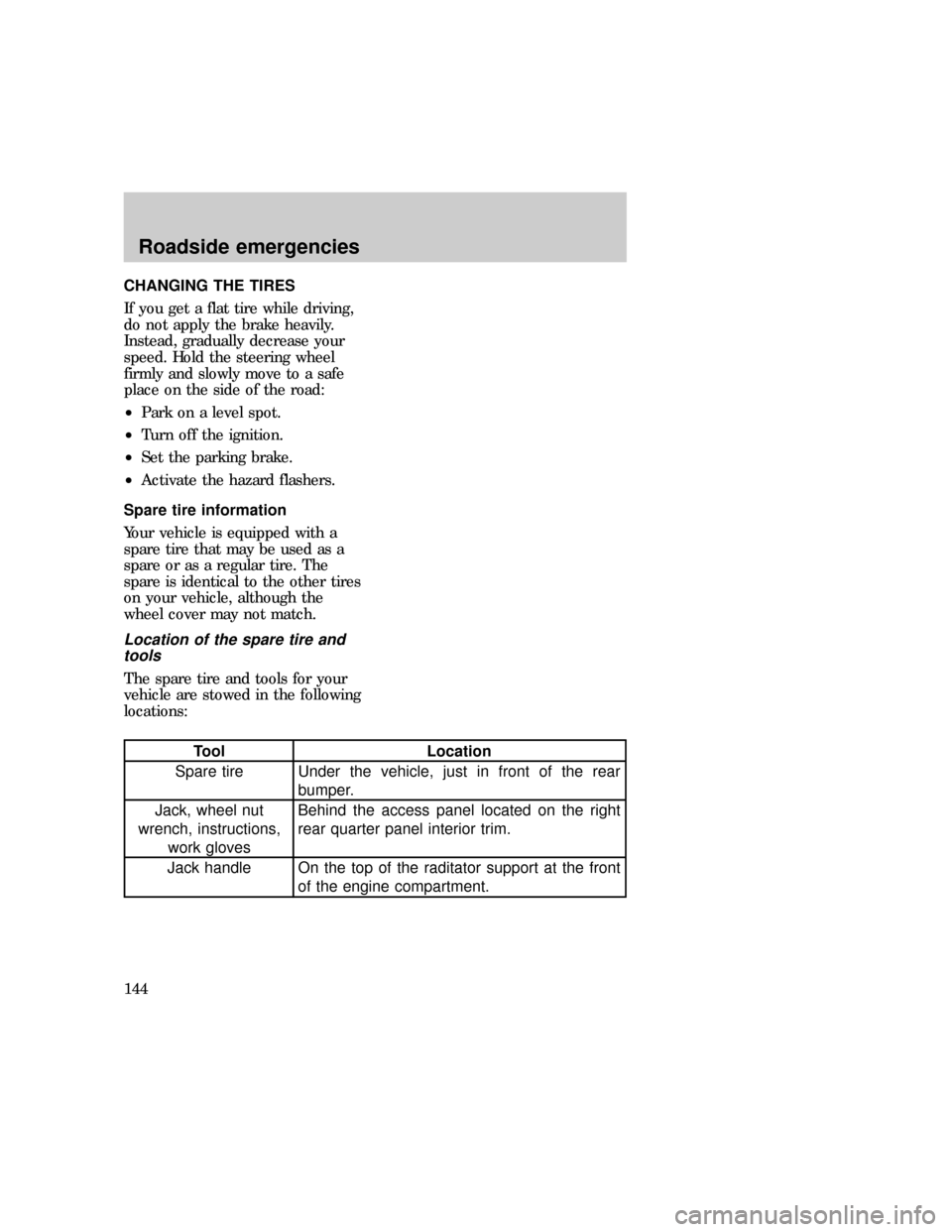
CHANGING THE TIRES
If you get a flat tire while driving,
do not apply the brake heavily.
Instead, gradually decrease your
speed. Hold the steering wheel
firmly and slowly move to a safe
place on the side of the road:
²Park on a level spot.
²Turn off the ignition.
²Set the parking brake.
²Activate the hazard flashers.
Spare tire information
Your vehicle is equipped with a
spare tire that may be used as a
spare or as a regular tire. The
spare is identical to the other tires
on your vehicle, although the
wheel cover may not match.
Location of the spare tire and
tools
The spare tire and tools for your
vehicle are stowed in the following
locations:
Tool Location
Spare tire Under the vehicle, just in front of the rear
bumper.
Jack, wheel nut
wrench, instructions,
work glovesBehind the access panel located on the right
rear quarter panel interior trim.
Jack handle On the top of the raditator support at the front
of the engine compartment.
exd_flat-tires_changing
exd_spare_location
exd_location_spare_tools
Roadside emergencies
144
Page 151 of 224
Connecting the jumper cables
1. Position the vehicles so that
they do not touch one another.
2. Switch off the engine. Switch off
any unnecessary electrical
equipment.
3. Connect the positive (+)
terminal of the discharged battery
(1) to the positive (+) terminal of
the booster battery (2).
4. Connect one end of the second
lead to the negative (-) terminal of
the booster battery (3) and the
other end to a metal part of the
engine to be started (4), not to the
negative (-) terminal of the
discharged battery.
5. Make sure that the jump leads
are clear of moving parts of the
engine.
Do not connect the end of
the second cable to the
negative ([-]) terminal of the
battery to be jumped. A spark
may cause an explosion of the
gases that surround the battery.
Jump starting
1. Start the booster vehicle and
run the engine at moderately
increased speed.
2. Start the engine of the vehicle
with the discharged battery.
+–
+–
3
2
1
4
com_jump_starting.01
Roadside emergencies
152