Page 25 of 62
15-21
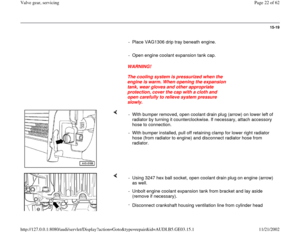
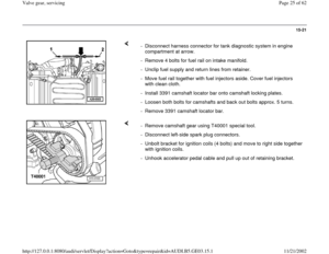
- Disconnect harness connector for tank diagnostic system in engine
compartment at arrow.
- Remove 4 bolts for fuel rail on intake manifold.
- Unclip fuel supply and return lines from retainer.
- Move fuel rail together with fuel injectors aside. Cover fuel injectors
with clean cloth.
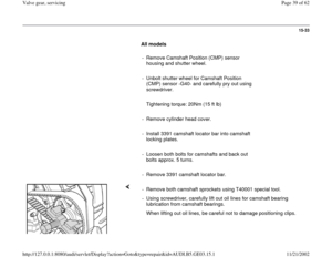
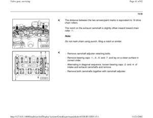
- Install 3391 camshaft locator bar onto camshaft locking plates.
- Loosen both bolts for camshafts and back out bolts approx. 5 turns.
- Remove 3391 camshaft locator bar.
- Remove camshaft gear using T40001 special tool.
- Disconnect left-side spark plug connectors.
- Unbolt bracket for ignition coils (4 bolts) and move to right side together
with ignition coils.
- Unhook accelerator pedal cable and pull up out of retaining bracket.
Pa
ge 25 of 62 Valve
gear, servicin
g
11/21/2002 htt
p://127.0.0.1:8080/audi/servlet/Dis
play?action=Goto&t
yp
e=re
pair&id=AUDI.B5.GE03.15.1
Page 26 of 62
15-22
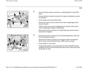
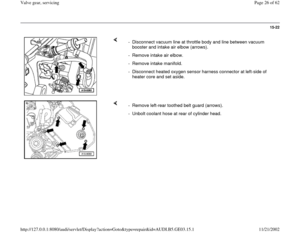
- Disconnect vacuum line at throttle body and line between vacuum
booster and intake air elbow (arrows).
- Remove intake air elbow.
- Remove intake manifold.
- Disconnect heated oxygen sensor harness connector at left-side of
heater core and set aside.
- Remove left-rear toothed belt guard (arrows).
- Unbolt coolant hose at rear of cylinder head.
Pa
ge 26 of 62 Valve
gear, servicin
g
11/21/2002 htt
p://127.0.0.1:8080/audi/servlet/Dis
play?action=Goto&t
yp
e=re
pair&id=AUDI.B5.GE03.15.1
Page 27 of 62
15-23
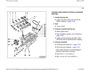
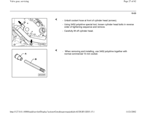
- Unbolt coolant hose at front of cylinder head (arrows).
- Using 3452 polydrive special tool, loosen cylinder head bolts in reverse
order of tightening sequence and remove.
- Carefully lift off cylinder head.
- When removing and installing, use 3452 polydrive together with
normal commercial 10 mm socket.
Pa
ge 27 of 62 Valve
gear, servicin
g
11/21/2002 htt
p://127.0.0.1:8080/audi/servlet/Dis
play?action=Goto&t
yp
e=re
pair&id=AUDI.B5.GE03.15.1
Page 28 of 62
15-24
Installing
Notes:
Bolt holes in engine block for cylinder head
bolts must be free of oil and coolant.
Always replace cylinder head bolts.
Vacuum line connections page 10-23
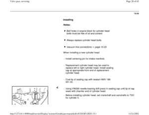
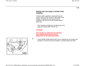
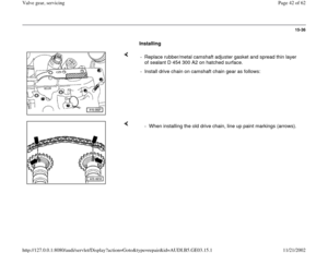
When installing a new cylinder head:
- Install centering pin for intake manifold.
- Replacement cylinder head may be used to
replace left or right cylinder head. Install sealing
cap at appropriate front end of replacement
cylinder head.
- Coat lip of sealing cap with sealant AMV 188
001 02.
- Using VW295 needle bearing drift press in sealing cap until lip of cap
seals with chamfer end of cylinder head.
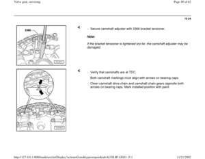
- Before installing cylinder head, set crankshaft and camshafts to TDC
for cylinder 3.
Pa
ge 28 of 62 Valve
gear, servicin
g
11/21/2002 htt
p://127.0.0.1:8080/audi/servlet/Dis
play?action=Goto&t
yp
e=re
pair&id=AUDI.B5.GE03.15.1
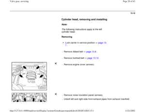
Page 29 of 62
- Install cylinder head gasket onto guide sleeves. Marking "oben" or Part
No. must face toward cylinder head.
- Install cylinder head, install cylinder head bolts and tighten hand-tight.
Pa
ge 29 of 62 Valve
gear, servicin
g
11/21/2002 htt
p://127.0.0.1:8080/audi/servlet/Dis
play?action=Goto&t
yp
e=re
pair&id=AUDI.B5.GE03.15.1
Page 30 of 62
15-25
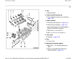
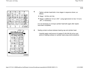
It is not necessary to re-torque cylinder head bolts again after repairs
have been completed. - Tighten cylinder head bolts in two stages in sequence shown, as
follows:
Stage 1: 60 Nm (44 ft lb) Stage 2: additional 1/2 turn (180 ) using rigid wrench (in two 1/4 turns
(90 ) if necessary).
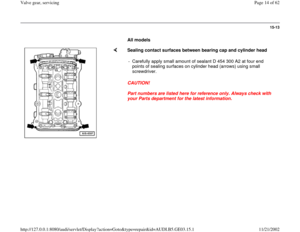
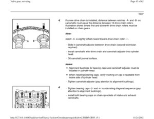
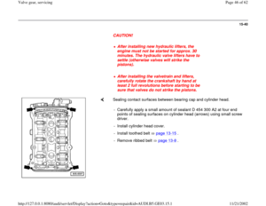
Sealing contact surfaces between bearing cap and cylinder head.
- Carefully apply small amount of sealant D 454 300 A2 at four end
points of sealing surfaces on cylinder head using small screwdriver.
Pa
ge 30 of 62 Valve
gear, servicin
g
11/21/2002 htt
p://127.0.0.1:8080/audi/servlet/Dis
play?action=Goto&t
yp
e=re
pair&id=AUDI.B5.GE03.15.1
Page 31 of 62
15-26
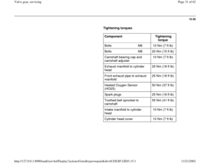
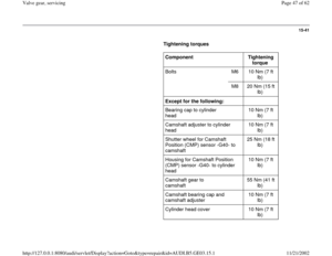
Tightening torques
Component
Tightening
torque
Bolts M6 10 Nm (7 ft lb)
Bolts M8 20 Nm (15 ft lb)
Camshaft bearing cap and
camshaft adjuster 10 Nm (7 ft lb)
Exhaust manifold to cylinder
head 25 Nm (18 ft lb)
Front exhaust pipe to exhaust
manifold 25 Nm (18 ft lb)
Heated Oxygen Sensor
(HO2S) 50 Nm (37 ft lb)
Spark plugs 25 Nm (18 ft lb)
Toothed belt sprocket to
camshaft 55 Nm (41 ft lb)
Intake manifold to cylinder
head 10 Nm (7 ft lb)
Cylinder head cover 10 Nm (7 ft lb)
Pa
ge 31 of 62 Valve
gear, servicin
g
11/21/2002 htt
p://127.0.0.1:8080/audi/servlet/Dis
play?action=Goto&t
yp
e=re
pair&id=AUDI.B5.GE03.15.1
Page 32 of 62
15-27
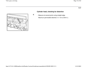
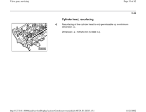
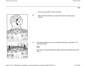
Cylinder head, checking for distortion
- Measure at several points using straight-edge.
Maximum permissible distortion: 0.1 mm (0.004 in.)
Pa
ge 32 of 62 Valve
gear, servicin
g
11/21/2002 htt
p://127.0.0.1:8080/audi/servlet/Dis
play?action=Goto&t
yp
e=re
pair&id=AUDI.B5.GE03.15.1

.
- Remove intake air elbow.
- Remove intake manifold.
- Disconnect heated ox")
.
- Using 3452 polydrive special tool, loosen cylinder head bolts in reverse
order of tightening sequence and remove.
- Carefu")


Bolts M8 20 Nm (15 ft lb)
Camshaft bearing cap and
camshaft adjuster 10 Nm (7 ft lb)
E")

Pa
ge 32 of 62 Valve
gear, servicin")