Page 17 of 19
50-17
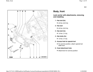
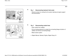
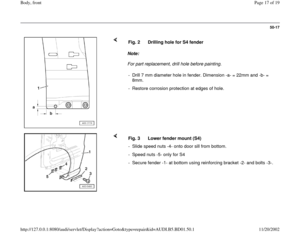
Note:
For part replacement, drill hole before painting. Fig. 2 Drilling hole for S4 fender
- Drill 7 mm diameter hole in fender. Dimension -a- = 22mm and -b- =
8mm.
- Restore corrosion protection at edges of hole.
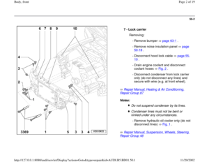
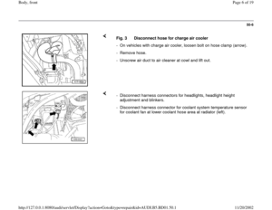
Fig. 3 Lower fender mount (S4)
- Slide speed nuts -4- onto door sill from bottom.
- Speed nuts -5- only for S4
- Secure fender -1- at bottom using reinforcing bracket -2- and bolts -3-.
Pa
ge 17 of 19 Bod
y, front
11/20/2002 htt
p://127.0.0.1:8080/audi/servlet/Dis
play?action=Goto&t
yp
e=re
pair&id=AUDI.B5.BD01.50.1
Page 18 of 19
50-18
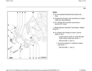
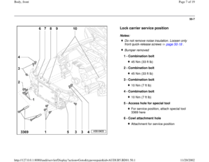
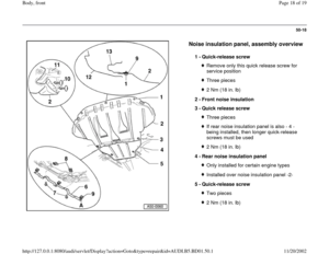
Noise insulation panel, assembly overview
1 -
Quick-release screw
Remove only this quick release screw for
service position Three pieces2 Nm (18 in. lb)
2 -
Front noise insulation
3 -
Quick release screw Three piecesIf rear noise insulation panel is also - 4 -
being installed, then longer quick-release
screws must be used 2 Nm (18 in. lb)
4 -
Rear noise insulation panel Only installed for certain engine typesInstalled over noise insulation panel -2-
5 -
Quick-release screw Two pieces2 Nm (18 in. lb)
Pa
ge 18 of 19 Bod
y, front
11/20/2002 htt
p://127.0.0.1:8080/audi/servlet/Dis
play?action=Goto&t
yp
e=re
pair&id=AUDI.B5.BD01.50.1
Page 19 of 19
50-19
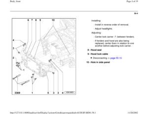
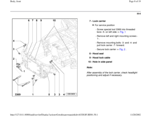
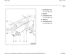
6 -
Mounting for noise insulation panel
Position -9- must face left side of vehicle
7 -
Bolt Two pieces7.5 Nm (66 in. lb)
8 -
Plate nut Two pieces
9 -
Plate nut Three pieces
10 -
Clamping pin Two pieces
11 -
Wheelhousing liner
12 -
Bumper
13 -
Lock carrier with attachments
Pa
ge 19 of 19 Bod
y, front
11/20/2002 htt
p://127.0.0.1:8080/audi/servlet/Dis
play?action=Goto&t
yp
e=re
pair&id=AUDI.B5.BD01.50.1
Page:
< prev 1-8 9-16 17-24


2 -
Front noise insulation
3")

8 -
Plate nut Two pieces
9 -
Plate nut Three pieces
10 -
Clam")