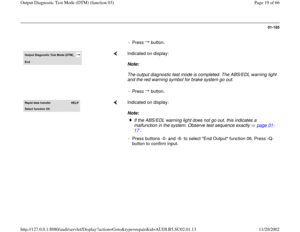
Page 57 of 66

00532
Voltage supply
Signal too small
Notes:
This malfunction affects the volt")
01-197
DTC
Possible cause
Corrective action
Printed output from VAG1551 Scan Tool
(ST)
00532
Voltage supply
Signal too small
Notes:
This malfunction affects the voltage supply
of the control module.
This DTC is only stored, if the malfunction
occurs at a vehicle speed above 6 km/h.
As soon as vehicle voltage is within the
valid voltage range again, the ABS/EDL or
ASR system is switched back on and the
warning lights turn off.
Open circuit or contact resistance
too high between voltage supply
from terminal 15 hydraulic control
unit, terminal 15. Voltage jumps in vehicle system.
Electrical Wiring Diagrams,
Troubleshooting & Component
Locations
Electrical Wiring Diagrams,
Troubleshooting & Component
Locations
Repair Manual, Electrical
Equipment, Repair Group 27.
- Carry out "Electrical test", step
1 page 01
-166
.
- Locate and repair open circuit
in voltage supply. - Check Generator (GEN) and
Voltage Regulator (VR). - Check battery
Malfunction in hydraulic control unit- If no malfunctions can be
found in the voltage supply,
replace hydraulic control unit.
Pa
ge 57 of 66 Out
put Dia
gnostic Test Mode
(DTM
) (function 03
)
11/20/2002 htt
p://127.0.0.1:8080/audi/servlet/Dis
play?action=Goto&t
yp
e=re
pair&id=AUDI.B5.SU02.01.13
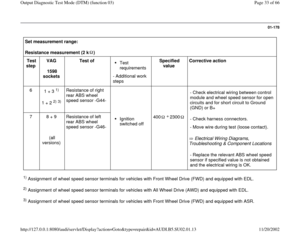
Page 58 of 66
01-198
DTC
Possible cause
Corrective action
Printed output from
VAG1551 Scan Tool (ST)
00597
Varying wheel speed
impulse
Wheel or tire sizes not the same on all four
wheels. - Check wheel and tire sizes.
ABS wheel speed sensor rotor dirty or
damaged.
Repair Manual, Brake System, Repair
Group 45
- Check rotor.
Excessive wheel bearing play.
Repair Manual, Suspension, Wheels,
Steering, Repair Group 40
Repair Manual, Suspension, Wheels,
Steering, Repair Group 42
- Check wheel bearing
ABS wheel speed sensors -G44-, -G45-, -G46-
, and -G47- installed incorrectly.
ABS wheel speed sensors -G44-, -G45-, -G46-
, and -G47- malfunctioning Repair Manual, Brake System, Repair
Group 45
- Check ABS wheel speed sensors.
- Carry out "electrical test", steps 4
through 7 page 01
-166
.
Pa
ge 58 of 66 Out
put Dia
gnostic Test Mode
(DTM
) (function 03
)
11/20/2002 htt
p://127.0.0.1:8080/audi/servlet/Dis
play?action=Goto&t
yp
e=re
pair&id=AUDI.B5.SU02.01.13
Page 59 of 66

00623
ABS / transmission
electrical connection
This malfunction only
occurs if veh")
01-199
DTC
Possible cause
Corrective action
Printed output from
VAG1551 Scan Tool
(ST)
00623
ABS / transmission
electrical connection
This malfunction only
occurs if vehicle is
equipped with ASR. Data is transferred between the ABS control
module -J104- and the Transmission Control
Module (TCM) via a single wire. For more information, see the section
"Systems related to ASR" page 01
-42
and the table "Control module versions"
page 01
-134
.
Manual transmission
ABS/EDL/ASR control module -J104-
incorrectly coded.
Short circuit to B+
Electrical Wiring Diagrams,
Troubleshooting & Component Locations - Check coding of ABS/EDL/ASR control
module -J104- page 01
-135
.
- Locate and repair short circuit.
Automatic transmission
ABS/EDL/ASR control module -J104-
incorrectly coded.
Open circuit or short circuit to Ground (GND)
in wiring between ABS/EDL/ASR control
module -J104- and Transmission Control
Module (TCM) -J217-.
Electrical Wiring Diagrams,
Troubleshooting & Component Locations - Check coding of ABS/EDL/ASR control
module -J104- page 01
-135
.
- Locate and repair open circuit or short
circuit.
Pa
ge 59 of 66 Out
put Dia
gnostic Test Mode
(DTM
) (function 03
)
11/20/2002 htt
p://127.0.0.1:8080/audi/servlet/Dis
play?action=Goto&t
yp
e=re
pair&id=AUDI.B5.SU02.01.13
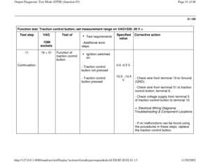
Page 60 of 66

00646
ABS-ASR motor electrical connection
1 Data is transferred between the ABS
contro")
01-200
DTC
Possible cause
Corrective action
Printed output from VAG1551 Scan
Tool (ST)
00646
ABS-ASR motor electrical connection
1 Data is transferred between the ABS
control module -J104- and the Engine
Control Module (ECM) via a single wire. For more information, see the section
"Systems related to ASR" page 01
-
42
and the table "Control module
versions" page 01
-134
.
Note:
The following signals are sent from
the ABS control module (w/EDL) -
J104- to the Engine Control Module
(ECM) via this connection:
Open circuit or short circuit to B+ or
Ground (GND) in wiring between ABS
control module -J104- terminal 13 and
Engine Control Module (ECM).
Electrical Wiring Diagrams,
Troubleshooting & Component
Locations - Locate and repair open circuit or
short circuit.
MMD signal (Masked Misfire
Diagnostic) for On Board
Diagnostic (OBD)
SET signal (Specified Engine
Torque)
ABS/EDL/ASR control module -J104-
malfunctioning. - Replace ABS/EDL/ASR hydraulic
control unit.
ETR signal (Engine Torque
Reduction signal)
Engine Control Module (ECM)
malfunctioning. - Replace Engine Control Module
(ECM).
Pa
ge 60 of 66 Out
put Dia
gnostic Test Mode
(DTM
) (function 03
)
11/20/2002 htt
p://127.0.0.1:8080/audi/servlet/Dis
play?action=Goto&t
yp
e=re
pair&id=AUDI.B5.SU02.01.13
Page 61 of 66

00647
ABS-ASR motor electrical
connection 2 Data is transferred between the ABS
contro")
01-201
DTC
Possible cause
Corrective action
Printed output from VAG1551
Scan Tool (ST)
00647
ABS-ASR motor electrical
connection 2 Data is transferred between the ABS
control module -J104- and the Engine
Control Module (ECM) via a single wire. For more information, see the section
"Systems related to ASR" page 01
-42
and the table "Control module versions"
page 01
-134
.
Note:
The following signal is sent from
the Engine Control Module (ECM)
to the ABS control module (w/EDL)
-J104- via this connection:
Open circuit or short circuit to B+ or
Ground (GND) in wiring between ABS
control module -J104- terminal 27 and
Engine Control Module (ECM).
Electrical Wiring Diagrams,
Troubleshooting & Component
Locations - Locate and repair open circuit or short
circuit.
AET signal (Actual Engine
Torque)
Engine Control Module (ECM)
malfunctioning. - Replace Engine Control Module
(ECM).
ABS/EDL/ASR control module -J104-
malfunctioning. - Replace ABS/EDL/ASR hydraulic
control unit.
Pa
ge 61 of 66 Out
put Dia
gnostic Test Mode
(DTM
) (function 03
)
11/20/2002 htt
p://127.0.0.1:8080/audi/servlet/Dis
play?action=Goto&t
yp
e=re
pair&id=AUDI.B5.SU02.01.13
Page 62 of 66
01-202
DTC
Possible cause
Corrective action
Printed output from
VAG1551 Scan Tool
(ST)
00761
DTC stored in Engine
Control Module (ECM)
This malfunction only
occurs if vehicle is
equipped with ASR. Data is transferred between ABS
control module -J104- and Engine
Control Module (ECM) via a single
wire or via the CAN-bus. For more information, see the section "Systems
related to ASR" page 01
-42
and the table "Control
module versions" page 01-134
.
A DTC was stored in the Engine
Control Module (ECM). The Engine
Control Module (ECM) is not able to
reduce engine torque. - Check DTC memory of Engine Control Module
(ECM). Repair the malfunction according to the
appropriate engine Repair Manual and erase DTC
memory of the Engine Control Module (ECM).
Pa
ge 62 of 66 Out
put Dia
gnostic Test Mode
(DTM
) (function 03
)
11/20/2002 htt
p://127.0.0.1:8080/audi/servlet/Dis
play?action=Goto&t
yp
e=re
pair&id=AUDI.B5.SU02.01.13
Page 63 of 66

01044
Control module incorrectly
coded
This malfunction only
occurs if vehicle is")
01-203
DTC
Possible cause
Corrective action
Printed output from
VAG1551 Scan Tool (ST)
01044
Control module incorrectly
coded
This malfunction only
occurs if vehicle is
equipped with ASR. Data is transferred between the ABS control
module -J104- and the Transmission Control
Module (TCM) via the CAN-bus. For more information, see the section
"Systems related to ASR" page 01
-42
and
the table "Control module versions" page
01
-134
.
The ABS control module (w/EDL) -J104- is
coded for a vehicle with manual
transmission. The vehicle is equipped with
automatic transmission. - Code the ABS control module (w/EDL) -
J104- for the correct transmission page
01
-135
.
01130
ABS operation
Implausible signal
- Replace the ABS control module (w/EDL) -
J104- after conferring with the product
department of your distributor or with the
responsible importer.
Pa
ge 63 of 66 Out
put Dia
gnostic Test Mode
(DTM
) (function 03
)
11/20/2002 htt
p://127.0.0.1:8080/audi/servlet/Dis
play?action=Goto&t
yp
e=re
pair&id=AUDI.B5.SU02.01.13
Page 64 of 66

01200
Supply voltage for ABS valves
Note:
This malfunction affects the voltage
su")
01-204
DTC
Possible cause
Corrective action
Printed output from VAG1551 Scan
Tool (ST)
01200
Supply voltage for ABS valves
Note:
This malfunction affects the voltage
supply of the ABS hydraulic unit -N55-
and the motor for the ABS hydraulic
pump -V64-.
Open circuit or contact resistance too
high between voltage supply from
terminal 30 hydraulic control unit,
terminals 17 and 18. Voltage jumps in vehicle system.
Electrical Wiring Diagrams,
Troubleshooting & Component
Locations
Electrical Wiring Diagrams,
Troubleshooting & Component
Locations
Repair Manual, Electrical
Equipment, Repair Group 27.
- Carry out "Electrical test", step
2 page 01
-166
.
- Locate and repair open circuit in
voltage supply. - Check Generator (GEN) and
Voltage Regulator (VR). - Check battery
Malfunction in hydraulic control unit- If no malfunctions can be found
in the voltage supply, replace
hydraulic control unit.
Pa
ge 64 of 66 Out
put Dia
gnostic Test Mode
(DTM
) (function 03
)
11/20/2002 htt
p://127.0.0.1:8080/audi/servlet/Dis
play?action=Goto&t
yp
e=re
pair&id=AUDI.B5.SU02.01.13


00597
Varying wheel speed
impulse
Wheel or tire sizes not the same on all four
wheel")

00761
DTC stored in Engine
Control Module (ECM)
This malfunction only
occurs if ve")