Page 25 of 66
01-171
Terminal
Wire connection to component ...
10
Electrical connection to instrument cluster
Only for vehicles equipped with EDL. The time signals used to calculate standing time are transmitted via
this harness connector
11
K-wire 13
MMD signal (Masked Misfire Diagnostic)
For vehicles equipped with ASR, the SET signal (Specified Engine Torque) is also transmitted via this wiring
harness.
14
Brake light switch -F- 15
Voltage supply, terminal 15 16
Ground (GND) terminal 31 (ABS hydraulic pump -V64-) 17
Battery + (terminal 30) 18
Battery + (terminal 30) 19
Ground (GND) terminal 31 (ABS control module -J104-) 20
Traction control (ASR) indicator light activation
Only for vehicles equipped with ASR.
21
ABS/EDL warning light activation 23
Speed sensor output rear left
For vehicles with navigation system
Pa
ge 25 of 66 Out
put Dia
gnostic Test Mode
(DTM
) (function 03
)
11/20/2002 htt
p://127.0.0.1:8080/audi/servlet/Dis
play?action=Goto&t
yp
e=re
pair&id=AUDI.B5.SU02.01.13
Page 26 of 66
24
Speed sensor output rear right
For vehicles with navigation system
Pa
ge 26 of 66 Out
put Dia
gnostic Test Mode
(DTM
) (function 03
)
11/20/2002 htt
p://127.0.0.1:8080/audi/servlet/Dis
play?action=Goto&t
yp
e=re
pair&id=AUDI.B5.SU02.01.13
Page 27 of 66
01-172
Terminal
Wire connection to component ...
27
AET (Actual Engine Torque)
Only for vehicles equipped with ASR.
28
TI (Transmission Influence)
Only for vehicles equipped with ASR.
29
CAN-bus low
The CAN-bus wires transmit the following signals to the appropriate control modules: AET (Actual Engine
Torque), SET (Specified Engine Torque), TI (Transmission Influence) and engine speed.
30
CAN-bus high
The CAN-bus wires transmit the following signals to the appropriate control modules: AET (Actual Engine
Torque), SET (Specified Engine Torque), TI (Transmission Influence) and engine speed.
30
Engine speed (RPM)
Only for vehicles equipped with ASR.
31
Traction control (ASR) button
Only for vehicles equipped with ASR.
Pa
ge 27 of 66 Out
put Dia
gnostic Test Mode
(DTM
) (function 03
)
11/20/2002 htt
p://127.0.0.1:8080/audi/servlet/Dis
play?action=Goto&t
yp
e=re
pair&id=AUDI.B5.SU02.01.13
Page 28 of 66
 -J104- in the wiring diagram. Incorrec")
01-173
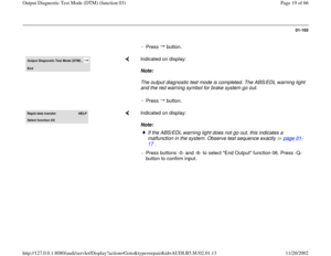
Notes:
For test table:
The socket designations of the VAG1598 test box are identical to the terminal designations of the ABS control module
(w/EDL) -J104- in the wiring diagram. Incorrect test procedures can cause damage to the system. Do not bridge any
terminals other than those listed in the table.
Electrical Wiring Diagrams, Troubleshooting & Component Locations Specified values refer to readings on the VAG1526 and are not necessarily applicable for other test units.
If the measured values do not match specifications, carry out the corrective actions listed on the right side of the table.
Electrical Wiring Diagrams, Troubleshooting & Component Locations If values are obtained, also check wiring for intermittent loose terminals and short circuit to B+ and Ground (GND). This
applies especially to sporadic malfunctions.
Use only the VAG1594 connector test kit for checking continuity (bridges).
If the measured values only differ slightly from the specifications, clean the sockets and harness connectors of the testers
and adapter leads (using contact spray G 000 700 04) and repeat the test. Before replacing actual components, check
wiring and connections once more. This is especially important if the specification for a resistance test is under 10 .
Pa
ge 28 of 66 Out
put Dia
gnostic Test Mode
(DTM
) (function 03
)
11/20/2002 htt
p://127.0.0.1:8080/audi/servlet/Dis
play?action=Goto&t
yp
e=re
pair&id=AUDI.B5.SU02.01.13
Page 29 of 66
01-174
Test table Set measurement range:
voltage test (20 V =)
Test
step VAG
1598
sockets Test of
Test
requirements
- Additional work
steps Specified
value Corrective action
1 19 + 15 Voltage supply to ABS
control module -J104- via
terminal 15 Ignition
switched on. 10.0 - 14.5
V
Electrical Wiring Diagrams,
Troubleshooting & Component
Locations - Check wire from terminal 19 to
Ground (GND).
- Check wire from terminal 15 to
terminal 15.
Pa
ge 29 of 66 Out
put Dia
gnostic Test Mode
(DTM
) (function 03
)
11/20/2002 htt
p://127.0.0.1:8080/audi/servlet/Dis
play?action=Goto&t
yp
e=re
pair&id=AUDI.B5.SU02.01.13
Page 30 of 66
01-175
Set measurement range:
voltage test (20 V =)
Test
step VAG
1598
sockets Test of
Test
requirements
- Additional work
steps Specified
value Corrective action
2 16 + 17 Voltage supply of ABS hydraulic unit -
N55- and motor for ABS hydraulic
pump -V64- via terminal 30 at ABS
control module (w/EDL) -J104- Ignition
switched on. 10.0 - 14.5
V - Check wire from terminal
16 to Ground (GND).
16 + 18 10.0 - 14.5
V
Electrical Wiring Diagrams,
Troubleshooting &
Component Locations - Check wiring from
terminals 17 and 18 to B+
(terminal 30) via fuse (60A).
Pa
ge 30 of 66 Out
put Dia
gnostic Test Mode
(DTM
) (function 03
)
11/20/2002 htt
p://127.0.0.1:8080/audi/servlet/Dis
play?action=Goto&t
yp
e=re
pair&id=AUDI.B5.SU02.01.13
Page 31 of 66
01-176
Set measurement range:
voltage test (20 V =)
Test
step VAG
1598
sockets Test of
Test requirements
- Additional work
steps Specified
value Corrective action
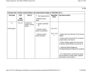
3 19 + 14 Function of brake
light switch -F- Ignition switched
off
- Check wire from terminal 19 to Ground
(GND).
Brake pedal not
depressed
- Operate brake pedal.0.0 -0.5 V
10.0 - 14.5
V
Electrical Wiring Diagrams,
Troubleshooting & Component Locations
Repair Manual, Brake System, Repair
Group 45
- Check wiring from terminal 14 to
terminal 30 via fuse (10A).
- Check brake light switch -F-
- Adjust brake light switch -F-.
Pa
ge 31 of 66 Out
put Dia
gnostic Test Mode
(DTM
) (function 03
)
11/20/2002 htt
p://127.0.0.1:8080/audi/servlet/Dis
play?action=Goto&t
yp
e=re
pair&id=AUDI.B5.SU02.01.13
Page 32 of 66
 Test
step VAG
1598
sockets Test of
Test
requirements
- Additional work
steps Specified
value Corrective action
4
4 + 5")
01-177
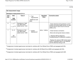
Set measurement range:
Resistance measurement (2 k ) Test
step VAG
1598
sockets Test of
Test
requirements
- Additional work
steps Specified
value Corrective action
4
4 + 5
1) 2)
3 + 5
3) Resistance of right
front ABS wheel
speed sensor -G45-
- Check electrical wiring between control
module and wheel speed sensor for open
circuit and for short circuit to Ground
(GND) or B+
5 6 + 7
(all
versions) Resistance of left
front ABS wheel
speed sensor -G47-
Ignition
switched off 400 2300
Electrical Wiring Diagrams,
Troubleshooting & Component Locations - Check harness connectors.
- Move wire during test (loose contact).- Replace the relevant ABS wheel speed
sensor if specified value is not obtained
and the electrical wiring is OK.
1) Assignment of wheel speed sensor terminals for vehicles with Front Wheel Drive (FWD) and equipped with EDL. 2) Assignment of wheel speed sensor terminals for vehicles with All Wheel Drive (AWD) and equipped with EDL. 3) Assignment of wheel speed sensor terminals for vehicles with Front Wheel Drive (FWD) and equipped with ASR.
Pa
ge 32 of 66 Out
put Dia
gnostic Test Mode
(DTM
) (function 03
)
11/20/2002 htt
p://127.0.0.1:8080/audi/servlet/Dis
play?action=Goto&t
yp
e=re
pair&id=AUDI.B5.SU02.01.13


 (function 03
)
11/20/2002 htt
p://127.0.0.1:8080/audi/servlet/Dis
play?ac")

Only for vehicles equipped with ASR.
28
TI (Transmission Influence)
Only for vehicles equipped with ASR.
29")

Test
step VAG
1598
sockets Test of
Test
requirements
- Additional work
steps Specified
value Corrective action
1 1")

Test
step VAG
1598
sockets Test of
Test
requirements
- Additional work
steps Specified
value Corrective action
2 16 + 17 Vo")

Test
step VAG
1598
sockets Test of
Test requirements
- Additional work
steps Specified
value Corrective action
3 19 + 14 Fun")