Page 1 of 12
13-67
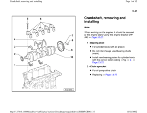
Crankshaft, removing and
installing Note:
When working on the engine, it should be secured
to the engine stand using the engine bracket VW
540 Page 10
-27
.
1 -
Bearing shell
For cylinder block with oil grooveDo not interchange used bearing shells
(mark). Install new bearing plates for cylinder block
with the correct color coding Fig. 2
,
Page 13
-72
2 -
Chain sprocket
For oil pump drive chainReplacing Page 13
-77
Pa
ge 1 of 12 Crankshaft, removin
g and installin
g
11/21/2002 htt
p://127.0.0.1:8080/audi/servlet/Dis
play?action=Goto&t
yp
e=re
pair&id=AUDI.B5.GE06.13.3
Page 2 of 12
13-68
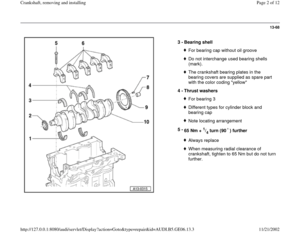
3 -
Bearing shell
For bearing cap without oil grooveDo not interchange used bearing shells
(mark). The crankshaft bearing plates in the
bearing covers are supplied as spare part
with the color coding "yellow"
4 -
Thrust washers For bearing 3Different types for cylinder block and
bearing cap Note locating arrangement
5 -
65 Nm +
1/4 turn (90 ) further
Always replaceWhen measuring radial clearance of
crankshaft, tighten to 65 Nm but do not turn
further.
Pa
ge 2 of 12 Crankshaft, removin
g and installin
g
11/21/2002 htt
p://127.0.0.1:8080/audi/servlet/Dis
play?action=Goto&t
yp
e=re
pair&id=AUDI.B5.GE06.13.3
Page 3 of 12
13-69
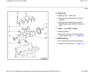
6 -
Bearing cap
Bearing cap 1: Pulley endBearing cap 3 with recesses for thrust
washers Bearing shell retaining lugs (cylinder
block/bearing cap) must be on the same
side
7 -
10 Nm +
1/4 turn (90 ) further
Always replaceAfter each removal of the bolts replace
sensor wheel Fig. 1
, Page 13
-71
8 -
Needle bearing
For vehicles with manual transmissionPulling out and driving in Page 13
-73
Pa
ge 3 of 12 Crankshaft, removin
g and installin
g
11/21/2002 htt
p://127.0.0.1:8080/audi/servlet/Dis
play?action=Goto&t
yp
e=re
pair&id=AUDI.B5.GE06.13.3
Page 4 of 12
13-70
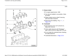
9 -
Sensor wheel
For engine speed sensor -G28-Can only be installed in one position. Holes
are offset Always replace sensor wheel if securing
bolts have been loosened. Removing and installing Fig. 1
,
Page 13
-71
10 -
Crankshaft
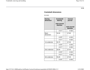
Axial clearance new: 0.07 to 00.23 mm,
Wear limit: 0.30 mm Check radial clearance with Plastigage ,
New: 0.02 to 0.04 mm, Wear limit: 0.15 mmDo not rotate the crankshaft when checking
the radial clearance. Crankshaft dimensions Page 13
-76Pa
ge 4 of 12 Crankshaft, removin
g and installin
g
11/21/2002 htt
p://127.0.0.1:8080/audi/servlet/Dis
play?action=Goto&t
yp
e=re
pair&id=AUDI.B5.GE06.13.3
Page 5 of 12
13-71
Note:
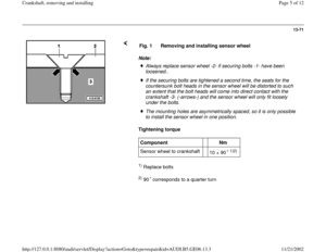
Tightening torque 1) Replace bolts 2) 90 corresponds to a quarter turn Fig. 1 Removing and installing sensor wheelAlways replace sensor wheel -2- if securing bolts -1- have been
loosened.. If the securing bolts are tightened a second time, the seats for the
countersunk bolt heads in the sensor wheel will be distorted to such
an extent that the bolt heads will come into direct contact with the
crankshaft -3- (-arrows-) and the sensor wheel will only fit loosely
under the bolts. The mounting holes are asymmetrically spaced, so it is only possible
to install the sensor wheel in one position.
Component
Nm
Sensor wheel to crankshaft
10 + 90
1)2)
Pa
ge 5 of 12 Crankshaft, removin
g and installin
g
11/21/2002 htt
p://127.0.0.1:8080/audi/servlet/Dis
play?action=Goto&t
yp
e=re
pair&id=AUDI.B5.GE06.13.3
Page 6 of 12
13-72
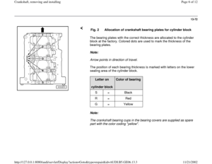
The bearing plates with the correct thickness are allocated to the cylinder
block at the factory. Colored dots are used to mark the thickness of the
bearing plates.
Note:
Arrow points in direction of travel.
The position of each bearing thickness is marked with letters on the lower
sealing area of the cylinder block.
Note:
The crankshaft bearing cups in the bearing covers are supplied as spare
part with the color coding "yellow". Fig. 2
Allocation of crankshaft bearing plates for cylinder block
Letter on
cylinder block
Color of bearing
S = Black
R = Red
G = Yellow
Pa
ge 6 of 12 Crankshaft, removin
g and installin
g
11/21/2002 htt
p://127.0.0.1:8080/audi/servlet/Dis
play?action=Goto&t
yp
e=re
pair&id=AUDI.B5.GE06.13.3
Page 7 of 12
13-73
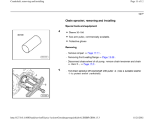
Crankshaft needle bearing, removing
and installing
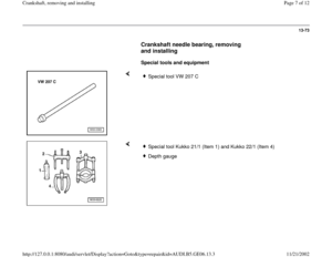
Special tools and equipment
Special tool VW 207 C
Special tool Kukko 21/1 (Item 1) and Kukko 22/1 (Item 4)Depth gauge
Pa
ge 7 of 12 Crankshaft, removin
g and installin
g
11/21/2002 htt
p://127.0.0.1:8080/audi/servlet/Dis
play?action=Goto&t
yp
e=re
pair&id=AUDI.B5.GE06.13.3
Page 8 of 12
13-74
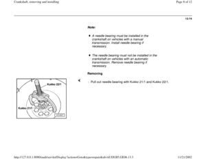
Note:
A needle bearing must be installed in the
crankshaft on vehicles with a manual
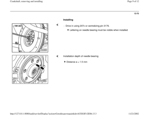
transmission. Install needle bearing if
necessary.
The needle bearing must not be installed in the
crankshaft on vehicles with an automatic
transmission. Remove needle bearing if
necessary.
Removing
- Pull out needle bearing with Kukko 21/1 and Kukko 22/1.
Pa
ge 8 of 12 Crankshaft, removin
g and installin
g
11/21/2002 htt
p://127.0.0.1:8080/audi/servlet/Dis
play?action=Goto&t
yp
e=re
pair&id=AUDI.B5.GE06.13.3

. The crankshaft bearing plates in the
bearing covers are supplied as spare part
with t")
 must be on the same
side
7 -
10 Nm +")

 Replace bolts 2) 90 corresponds to a quarter turn Fig. 1 Removing and installing sensor wheelAlways replace sensor wheel -2- if securing bolts -1- have be")

 and Kukko 22/1 (Item 4)Depth g")
