Page 33 of 47
13-33
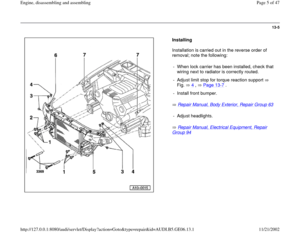
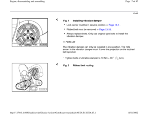
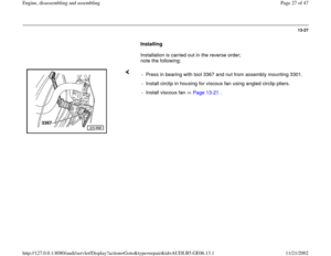
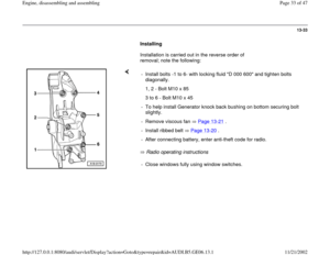
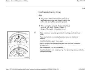
Installing
Installation is carried out in the reverse order of
removal; note the following:
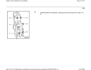
Radio operating instructions - Install bolts -1 to 6- with locking fluid "D 000 600" and tighten bolts
diagonally.
1, 2 - Bolt M10 x 85
3 to 6 - Bolt M10 x 45
- To help install Generator knock back bushing on bottom securing bolt
slightly.
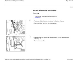
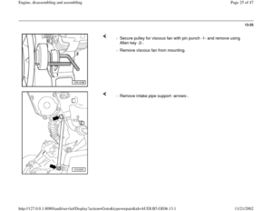
- Remove viscous fan Page 13
-21
.
- Install ribbed belt Page 13
-20
.
- After connecting battery, enter anti-theft code for radio.- Close windows fully using window switches.
Pa
ge 33 of 47 En
gine, disassemblin
g and assemblin
g
11/21/2002 htt
p://127.0.0.1:8080/audi/servlet/Dis
play?action=Goto&t
yp
e=re
pair&id=AUDI.B5.GE06.13.1
Page 34 of 47
13-34
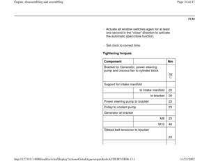
- Actuate all window switches again for at least
one second in the "close" direction to activate
the automatic open/close function.
- Set clock to correct time.
Tightening torques
Component
Nm
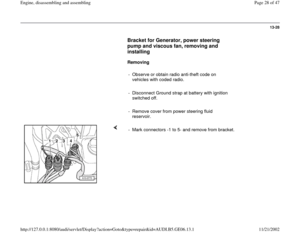
Bracket for Generator, power steering
pump and viscous fan to cylinder block
52
1)
Support for intake manifold
to intake manifold 20
to bracket 20
Power steering pump to bracket 23
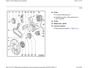
Pulley to coolant pump 23
Generator at bracket
M8 23
M10 46
Ribbed belt tensioner to bracket
23
Pa
ge 34 of 47 En
gine, disassemblin
g and assemblin
g
11/21/2002 htt
p://127.0.0.1:8080/audi/servlet/Dis
play?action=Goto&t
yp
e=re
pair&id=AUDI.B5.GE06.13.1
Page 35 of 47
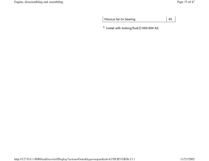
Viscous fan to bearing 45
1) Install with locking fluid D 000 600 A2
Pa
ge 35 of 47 En
gine, disassemblin
g and assemblin
g
11/21/2002 htt
p://127.0.0.1:8080/audi/servlet/Dis
play?action=Goto&t
yp
e=re
pair&id=AUDI.B5.GE06.13.1
Page 36 of 47
13-35
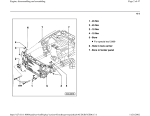
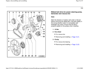
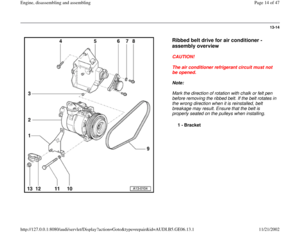
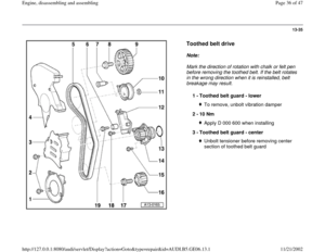
Toothed belt drive
Note:
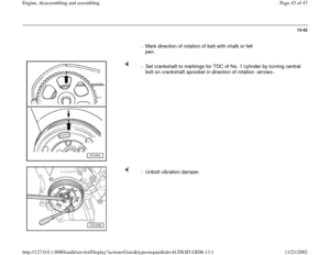
Mark the direction of rotation with chalk or felt pen
before removing the toothed belt. If the belt rotates
in the wrong direction when it is reinstalled, belt
breakage may result.
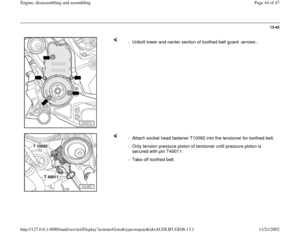
1 -
Toothed belt guard - lower
To remove, unbolt vibration damper
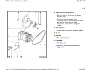
2 -
10 Nm Apply D 000 600 when installing
3 -
Toothed belt guard - center Unbolt tensioner before removing center
section of toothed belt guard
Pa
ge 36 of 47 En
gine, disassemblin
g and assemblin
g
11/21/2002 htt
p://127.0.0.1:8080/audi/servlet/Dis
play?action=Goto&t
yp
e=re
pair&id=AUDI.B5.GE06.13.1
Page 37 of 47
13-36
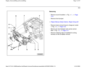
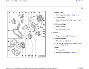
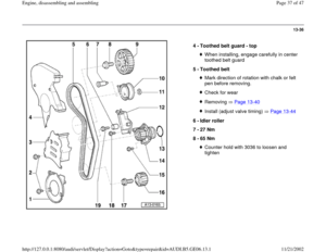
4 -
Toothed belt guard - top
When installing, engage carefully in center
toothed belt guard
5 -
Toothed belt Mark direction of rotation with chalk or felt
pen before removing. Check for wearRemoving Page 13
-40
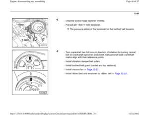
Install (adjust valve timing) Page 13
-44
6 -
Idler roller
7 -
27 Nm
8 -
65 Nm
Counter hold with 3036 to loosen and
tighten
Pa
ge 37 of 47 En
gine, disassemblin
g and assemblin
g
11/21/2002 htt
p://127.0.0.1:8080/audi/servlet/Dis
play?action=Goto&t
yp
e=re
pair&id=AUDI.B5.GE06.13.1
Page 38 of 47
13-37
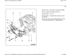
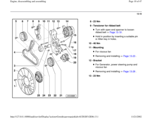
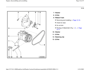
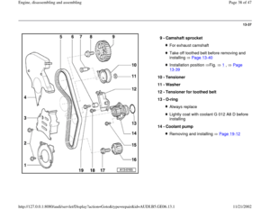
9 -
Camshaft sprocket
For exhaust camshaftTake off toothed belt before removing and
installing Page 13
-40
Installation position Fig. 1
, Page
13
-39
10 -
Tensioner
11 -
Washer
12 -
Tensioner for toothed belt
13 -
O-ring
Always replaceLightly coat with coolant G 012 A8 D before
installing
14 -
Coolant pump Removing and installing Page 19
-12
Pa
ge 38 of 47 En
gine, disassemblin
g and assemblin
g
11/21/2002 htt
p://127.0.0.1:8080/audi/servlet/Dis
play?action=Goto&t
yp
e=re
pair&id=AUDI.B5.GE06.13.1
Page 39 of 47
13-38
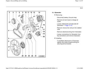
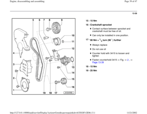
15 -
15 Nm
16 -
Crankshaft sprocket
Contact surface between sprocket and
crankshaft must be free of oil. Can only be installed in one position.
17 -
90 Nm +
1/4 turn (90 ) further
Always replaceDo not use oilCounter hold with 3415 to loosen and
tighten Fasten counterhold 3415 Fig. 2
,
Page 13
-39
18 -
15 Nm
19 -
25 Nm
Pa
ge 39 of 47 En
gine, disassemblin
g and assemblin
g
11/21/2002 htt
p://127.0.0.1:8080/audi/servlet/Dis
play?action=Goto&t
yp
e=re
pair&id=AUDI.B5.GE06.13.1
Page 40 of 47
13-39
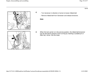
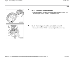
Fig. 1 Location of camshaft sprocket
The narrow web of the camshaft sprocket faces outward -arrows- and
the marking for TDC of cylinder 1 is visible from front.
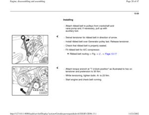
Fig. 2 Removing and installing toothed belt crankshaft
- Use counter-hold tool 3415 to loosen and tighten the central bolt.
Pa
ge 40 of 47 En
gine, disassemblin
g and assemblin
g
11/21/2002 htt
p://127.0.0.1:8080/audi/servlet/Dis
play?action=Goto&t
yp
e=re
pair&id=AUDI.B5.GE06.13.1


 Install with locking fluid D 000 600 A2
Pa
ge 35 of 47 En
gine, disassemblin
g and assemblin
g
11/21/2002 htt
p://127.0.0.1:8080/audi/servlet/Dis
play?action=G")


 further
A")
