Page 17 of 47
13-17
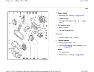
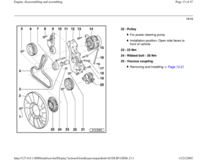
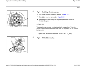
Parts List
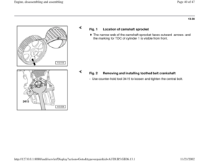
The vibration damper can only be installed in one position. The hole -
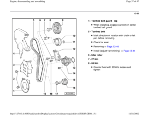
arrow- in the vibration damper must fit over the projection on the toothed
belt sprocket. Fig. 1 Installing vibration damperLock carrier must be in service position Page 13
-1 .
Ribbed belt must be removed Page 13
-18
.
Always replace bolts. Only use original type bolts to install the
vibration damper.
-
Tighten bolts of vibration damper to 10 Nm + 90 (
1/4turn).
Fig. 2 Ribbed belt routing
Pa
ge 17 of 47 En
gine, disassemblin
g and assemblin
g
11/21/2002 htt
p://127.0.0.1:8080/audi/servlet/Dis
play?action=Goto&t
yp
e=re
pair&id=AUDI.B5.GE06.13.1
Page 18 of 47
13-18
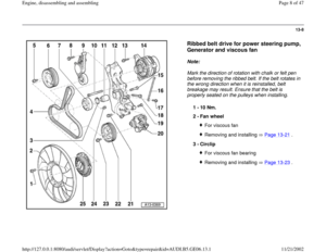
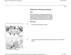
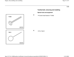
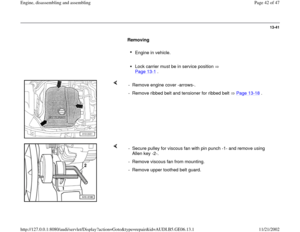
Ribbed belt, removing and installing
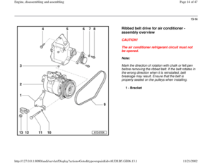
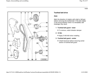
Note:
Mark the direction of rotation with chalk or felt
pen before removing the ribbed belt. If the belt
rotates in the wrong direction when it is refitted,
belt breakage may result. Ensure that the belt is
properly seated on the pulleys when installing.
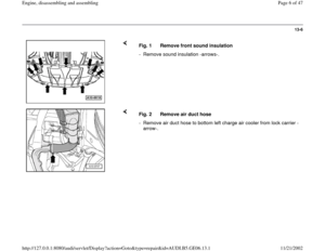
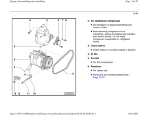
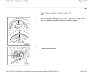
Removing
- Remove sound insulation -arrows-.
- Loosen bolts securing ribbed belt tensioning roller for A/C compressor -
arrows-.
Pa
ge 18 of 47 En
gine, disassemblin
g and assemblin
g
11/21/2002 htt
p://127.0.0.1:8080/audi/servlet/Dis
play?action=Goto&t
yp
e=re
pair&id=AUDI.B5.GE06.13.1
Page 19 of 47
13-19
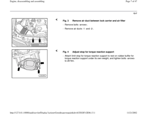
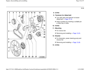
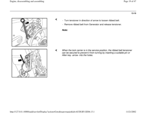
Note: - Turn tensioner in direction of arrow to loosen ribbed belt.
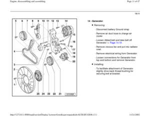
- Remove ribbed belt from Generator and release tensioner.
When the lock carrier is in the service position, the ribbed belt tensioner
can be secured to prevent it from turning by inserting a suitable pin or
Allen key -arrow- into the holes.
Pa
ge 19 of 47 En
gine, disassemblin
g and assemblin
g
11/21/2002 htt
p://127.0.0.1:8080/audi/servlet/Dis
play?action=Goto&t
yp
e=re
pair&id=AUDI.B5.GE06.13.1
Page 20 of 47
13-20
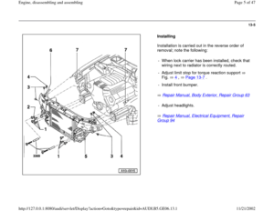
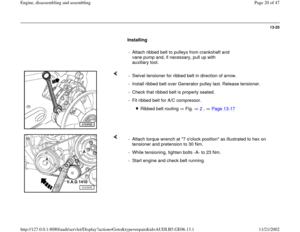
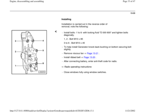
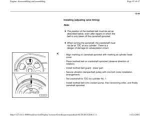
Installing
- Attach ribbed belt to pulleys from crankshaft and
vane pump and, if necessary, pull up with
auxiliary tool.
- Swivel tensioner for ribbed belt in direction of arrow.
- Install ribbed belt over Generator pulley last. Release tensioner.
- Check that ribbed belt is properly seated.
- Fit ribbed belt for A/C compressor.
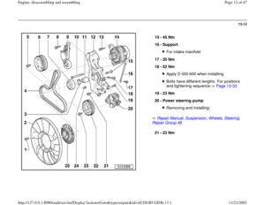
Ribbed belt routing Fig. 2
, Page 13
-17
- Attach torque wrench at "7 o'clock position" as illustrated to hex on
tensioner and pretension to 30 Nm.
- While tensioning, tighten bolts -A- to 23 Nm.
- Start engine and check belt running.
Pa
ge 20 of 47 En
gine, disassemblin
g and assemblin
g
11/21/2002 htt
p://127.0.0.1:8080/audi/servlet/Dis
play?action=Goto&t
yp
e=re
pair&id=AUDI.B5.GE06.13.1
Page 21 of 47
13-21
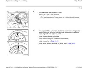
Viscous fan, removing and installing
Removing
Lock carrier must be in service position
Page 13
-1 .
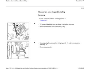
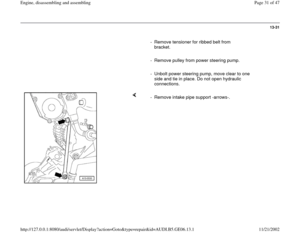
- To loosen ribbed belt, turn tensioner in direction of arrow.
- Remove ribbed belt from Generator pulley.
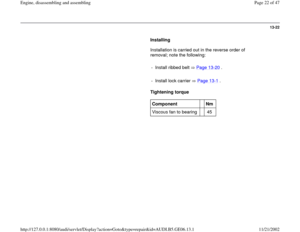
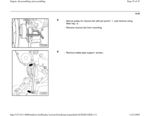
- Secure pulley for viscous fan with pin punch -1- and remove using
Allen key -2-.
- Remove viscous fan.
Pa
ge 21 of 47 En
gine, disassemblin
g and assemblin
g
11/21/2002 htt
p://127.0.0.1:8080/audi/servlet/Dis
play?action=Goto&t
yp
e=re
pair&id=AUDI.B5.GE06.13.1
Page 22 of 47
13-22
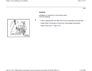
Installing
Installation is carried out in the reverse order of
removal; note the following:
- Install ribbed belt Page 13
-20
.
- Install lock carrier Page 13
-1 .
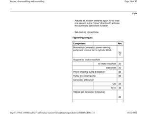
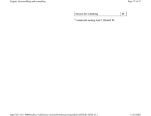
Tightening torque
Component
Nm
Viscous fan to bearing 45
Pa
ge 22 of 47 En
gine, disassemblin
g and assemblin
g
11/21/2002 htt
p://127.0.0.1:8080/audi/servlet/Dis
play?action=Goto&t
yp
e=re
pair&id=AUDI.B5.GE06.13.1
Page 23 of 47
13-23
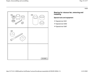
Bearing for viscous fan, removing and
installing
Special tools and equipment
Special tool 3301
Special tool 3350
Special tool 3367
Pa
ge 23 of 47 En
gine, disassemblin
g and assemblin
g
11/21/2002 htt
p://127.0.0.1:8080/audi/servlet/Dis
play?action=Goto&t
yp
e=re
pair&id=AUDI.B5.GE06.13.1
Page 24 of 47
13-24
Removing
Lock carrier must be in service position
Page 13
-1 .
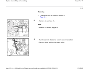
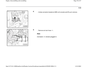
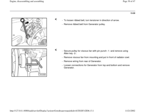
Note:
Connector -2- remains plugged in. - Remove air duct hose -1-.
- Turn tensioner in direction of arrow to loosen ribbed belt.
- Remove ribbed belt from Generator pulley.
Pa
ge 24 of 47 En
gine, disassemblin
g and assemblin
g
11/21/2002 htt
p://127.0.0.1:8080/audi/servlet/Dis
play?action=Goto&t
yp
e=re
pair&id=AUDI.B5.GE06.13.1