Page 25 of 37
24-101
Shift procedure, checking
Notes:
The Engine Control Module (ECM) uses this
signal to briefly retard the ignition during shifting
to reduce the mechanical jerking felt between
shifts.
The shift signal is monitored by the
Transmission Control Module (TCM).
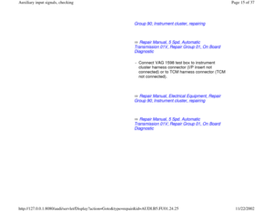
Repair Manual, 5 Spd. Automatic
Transmission 01V, Repair Group 01; On Board Diagnostic
Carry out the following check only if a shift-
related DTC is stored in the TCM DTC memory.
Checking requirement
Control module coding OK page 01
-247
CAUTION!
Always use a second technician to operate
the VAG 1551 scan tool while driving.
Pa
ge 25 of 37 Auxiliar
y in
put si
gnals, checkin
g
11/22/2002 htt
p://127.0.0.1:8080/audi/servlet/Dis
play?action=Goto&t
yp
e=re
pair&id=AUDI.B5.FU01.24.25
Page 26 of 37
- Test drive and select "Read Measuring Value
Block" function 08, display group 004 page
01
-249
.
Pa
ge 26 of 37 Auxiliar
y in
put si
gnals, checkin
g
11/22/2002 htt
p://127.0.0.1:8080/audi/servlet/Dis
play?action=Goto&t
yp
e=re
pair&id=AUDI.B5.FU01.24.25
Page 27 of 37
24-102
Read measuring value block 4 1 2 3 4
Indicated on display; note display field 4
Notes:
Due to its short signal duration, shifting cannot always be observed on the
VAG 1551 scan tool.
CAUTION!
Do not use the shift inputs (identified by an X) during the shift signal
check.
If the change in the shift signal display did not occur, even though the
control module coding was OK: Specified value: XXX_X0
Shift value must increase briefly during shifting.
Specified value: XXX_X1
-
Press button.
- Select "End Output" function 06.
- Press -Q- button to confirm input.
- Connect VAG 1598/19 test box to ECM harness connector page 01
-
255
.
- Check wiring for open or short circuit between ECM and TCM, using
wiring diagram.
Pa
ge 27 of 37 Auxiliar
y in
put si
gnals, checkin
g
11/22/2002 htt
p://127.0.0.1:8080/audi/servlet/Dis
play?action=Goto&t
yp
e=re
pair&id=AUDI.B5.FU01.24.25
Page 28 of 37
24-103
Upshift and downshift signals, checking
Notes:
The Engine Control Module (ECM) uses this
signal in connection with the shift signal to
determine whether the current signal is an
upshift or downshift.
The signal for upshift and downshift is
monitored by the Transmission Control Module
(TCM).
Repair Manual, 5 Spd. Automatic
Transmission 01V, Repair Group 01; On Board Diagnostic
Checking requirement
Control module coding OK page 01
-247
.
Pa
ge 28 of 37 Auxiliar
y in
put si
gnals, checkin
g
11/22/2002 htt
p://127.0.0.1:8080/audi/servlet/Dis
play?action=Goto&t
yp
e=re
pair&id=AUDI.B5.FU01.24.25
Page 29 of 37
24-104
Throttle position sensor output signal,
checking
Notes:
The Transmission Control Module (TCM)
interprets this information as a load signal.
This signal is monitored by the TCM.
Repair Manual, 5 Spd. Automatic
Transmission 01V, Repair Group 01; On Board Diagnostic
Checking requirement
Control module coding OK page 01
-247
.
Pa
ge 29 of 37 Auxiliar
y in
put si
gnals, checkin
g
11/22/2002 htt
p://127.0.0.1:8080/audi/servlet/Dis
play?action=Goto&t
yp
e=re
pair&id=AUDI.B5.FU01.24.25
Page 30 of 37
24-105
Malfunction Indicator Lamp (MIL) wire
from Transmission Control Module
(TCM), checking
Notes:
If a malfunction is recognized by the Engine
Control Module (ECM) or the Transmission
Control Module (TCM), it is indicated by the
Malfunction Indicator Lamp (MIL) in the
instrument cluster.
If the TCM recognizes a malfunction, the MIL is
switched on via the ECM.
The MIL wiring is monitored by the ECM.
Checking requirement
Control module coding OK page 01
-247
.
Pa
ge 30 of 37 Auxiliar
y in
put si
gnals, checkin
g
11/22/2002 htt
p://127.0.0.1:8080/audi/servlet/Dis
play?action=Goto&t
yp
e=re
pair&id=AUDI.B5.FU01.24.25
Page 31 of 37
24-106
- Switch ignition ON.
- Using VAG 1551 scan tool, select "Read
Measuring Value Block" function 08, display
group 027, display field 1 page 01
-249
.
Read measuring value block 27 1 2 3 4
Indicated on display; note display field 1
If the specified value is not obtained, even though coding is OK: Specified value: 0
- Start engine and let idle.
Specified value: 1
-
Press button.- Select "End Output" function 06.
- Press -Q- button to confirm input.
- Connect VAG 1598/19 test box to ECM harness connector page 01
-
255
.
- Check wiring for open or short circuit between ECM and TCM, using
wiring diagram.
Pa
ge 31 of 37 Auxiliar
y in
put si
gnals, checkin
g
11/22/2002 htt
p://127.0.0.1:8080/audi/servlet/Dis
play?action=Goto&t
yp
e=re
pair&id=AUDI.B5.FU01.24.25
Page 32 of 37
24-107
Fuel level signal (from instrument
cluster), checking
Notes:
If the fuel level in the tank is too low (less than
3.2 gal); combustion misfire, oxygen sensor and
fuel system malfunctions could occur. In these
cases the malfunction "Fuel tank level too low"
is stored in DTC memory.
The fuel tank level signal is monitored by the
Engine Control Module (ECM).
Checking requirements:
Control Module coding OK page 01
-247
.
Fuel content greater than 3.2 gal (12 liters).
Instrument cluster fuel gauge OK.
Pa
ge 32 of 37 Auxiliar
y in
put si
gnals, checkin
g
11/22/2002 htt
p://127.0.0.1:8080/audi/servlet/Dis
play?action=Goto&t
yp
e=re
pair&id=AUDI.B5.FU01.24.25


 uses this
signal to briefly retard the ignition during shifting
to reduce the mechanical jerking felt b")


 uses this
signal in connection with the shift signal to
determine whether the current si")

interprets this information as a load signal.
This signal is monitor")
 wire
from Transmission Control Module
(TCM), checking
Notes:
If a malfunction is recognized by the Engine
Control Module (ECM) or the")

, checking
Notes:
If the fuel level in the tank is too low (less than
3.2 gal); combustion misfire, oxygen sensor and
fuel s")