Page 17 of 37
If wiring OK and the specified value is not obtained: - Check wiring between ECM terminal C12 and black 20-pin trip
computer connector, using wiring diagram.
- Replace ECM page 01
-265
.
Pa
ge 17 of 37 Auxiliar
y in
put si
gnals, checkin
g
11/22/2002 htt
p://127.0.0.1:8080/audi/servlet/Dis
play?action=Goto&t
yp
e=re
pair&id=AUDI.B5.FU01.24.25
Page 18 of 37
24-97
Vehicle speed signal, checking
Note:
The vehicle speed signal originates from the
vehicle speed sensor (on the transmission) and
is routed to the instrument cluster as well as to
the Engine Control Module (ECM).
Speedometer in instrument cluster OK
Checking
- Using VAG 1551 scan tool, select "Read
Measuring Value Block" function 08, display
group 003 page 01
-249
.
Read measuring value block 3 1 2 3 4
Indicated on display
- Observe display field 4 while accelerating from standstill.
Specified values:
0 mph (at standstill)
Actual speed (vehicle driven)
-
Press button.
- Select "End Output" function 06.
- Press -Q- button to confirm input.
Pa
ge 18 of 37 Auxiliar
y in
put si
gnals, checkin
g
11/22/2002 htt
p://127.0.0.1:8080/audi/servlet/Dis
play?action=Goto&t
yp
e=re
pair&id=AUDI.B5.FU01.24.25
Page 19 of 37
24-98
If no vehicle speed is displayed between
standstill and moving:
- Switch ignition OFF and connect VAG 1598/19
test box page 01
-255
.
- Connect VAG 1527B voltage tester between test
box sockets 13C (signal) and 10D (B+).
- Raise front of vehicle until left-front wheel is free
to rotate.
Note:
The right front wheel must NOT rotate.
- Switch ignition ON.
Voltage tester must light up at half strength
- Rotate left front wheel by hand.
Voltage tester must become brighter (flash)
If tester does not light up (become brighter) or
flash:
-
Check wiring between test box socket 13X and
Pa
ge 19 of 37 Auxiliar
y in
put si
gnals, checkin
g
11/22/2002 htt
p://127.0.0.1:8080/audi/servlet/Dis
play?action=Goto&t
yp
e=re
pair&id=AUDI.B5.FU01.24.25
Page 20 of 37
vehicle speed sensor, using wiring diagram.
If wiring is OK, replace vehicle speed sensor.
If voltage tester does not light up (become brighter) or flash, replace ECM
page 01
-265
. - Find and eliminate open circuit in wiring between terminal C13 and
vehicle speed sensor.
Pa
ge 20 of 37 Auxiliar
y in
put si
gnals, checkin
g
11/22/2002 htt
p://127.0.0.1:8080/audi/servlet/Dis
play?action=Goto&t
yp
e=re
pair&id=AUDI.B5.FU01.24.25
Page 21 of 37
24-99
Transmission Range (TR) selector lever
position signal, checking
Note:
The Engine Control Module (ECM) uses this
signal to recognize the transmission range
selector lever position. When a driving mode is
selected, idle speed should drop by approx. 50
RPM to reduce creep.
Checking requirement
Control module coding OK page 01
-247
.
- Switch ignition ON.
- Using VAG 1551 scan tool, select "Read
Measuring Value Block" function 08, display
group 004, display field 4 page 01
-249
.
Read measuring value block 4 1 2 3 4
Indicated on display
CAUTION! Specified value: XXX_1X (TR selector lever in P or N)
- Apply brake and select drive mode (1, 2, 3, R or D).
Specified value: XXX_0X
Pa
ge 21 of 37 Auxiliar
y in
put si
gnals, checkin
g
11/22/2002 htt
p://127.0.0.1:8080/audi/servlet/Dis
play?action=Goto&t
yp
e=re
pair&id=AUDI.B5.FU01.24.25
Page 22 of 37
Do not use the shift inputs (identified by an X) during the selector
lever position check.
Pa
ge 22 of 37 Auxiliar
y in
put si
gnals, checkin
g
11/22/2002 htt
p://127.0.0.1:8080/audi/servlet/Dis
play?action=Goto&t
yp
e=re
pair&id=AUDI.B5.FU01.24.25
Page 23 of 37
24-100
-
Press button.
- Select "End Output" function 06 and press -Q-
button to confirm input.
If a display did NOT change, even though coding
is OK:
- Connect VAG 1598/19 test box to ECM harness
connector page 01
-255
.
- Connect VAG 1527B voltage tester between test
box sockets 11B (signal) and 10B (constant
B+/terminal 30).
Voltage tester must light up (with TR selector
lever in P or N), then go out with drive mode
(1, 2, 3, R or D) selected
If voltage tester lights up and goes out when
drive mode is selected, even though the range
indicator in the "Read measuring value block" is
OK:
- Replace ECM page 01
-265
.
If voltage tester lights up constantly or not at all:
-
Check wiring for short to ground, short to B+ or open circuit between
Pa
ge 23 of 37 Auxiliar
y in
put si
gnals, checkin
g
11/22/2002 htt
p://127.0.0.1:8080/audi/servlet/Dis
play?action=Goto&t
yp
e=re
pair&id=AUDI.B5.FU01.24.25
Page 24 of 37
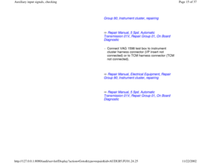
If wiring is OK:
Repair Manual, 5 Spd. Automatic Transmission 01V, Repair Group 01; Electrical test.
ECM terminal 11B and multi-function switch, using wiring diagram.
- Check multi-function switch.
Pa
ge 24 of 37 Auxiliar
y in
put si
gnals, checkin
g
11/22/2002 htt
p://127.0.0.1:8080/audi/servlet/Dis
play?action=Goto&t
yp
e=re
pair&id=AUDI.B5.FU01.24.25


 and
is routed to the instrument cluster as we")

 or flash, replace ECM
page 01
-265
. - Fi")
 selector lever
position signal, checking
Note:
The Engine Control Module (ECM) uses this
signal to recognize the transmission range
selector leve")
 during the selector
lever position check.
Pa
ge 22 of 37 Auxiliar
y in
put si
gnals, checkin
g
11/22/2002 htt
p://127.0.0.1:8080/audi/servlet/Dis
pla")

