Page 17 of 23
01-27
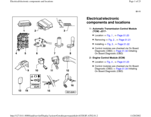
Location: The multi-function switch -1- is located on left at transmission;
Multi-pin connector for multi-function switch -arrow-.
Multi-function TR switch, removing and installing
Repair Manual, 5 Spd. Automatic Transmission 01V, Repair Group 38
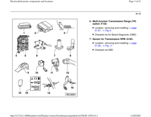
Fig. 8 Multi-function Transmission Range (TR) switch -F125-
Installation location: The tiptronic switch is integrated into the conductor
strip of the symbol insert in the cover of the shift mechanism.
Note:
This switch is not installed on shift mechanisms without tiptronic function.
The switch consists of 3 hall-effect sensors (-A-, -B-, -C- ), which are
activated via a magnet on the lateral gate cover of the gate cover. Fig. 9 Tiptronic switch -F189-
A - Sensor for down-shift
B - Sensor for Tiptronic-recognition
C - Sensor for up-shift
Pa
ge 17 of 23 Electrical/electronic com
ponents and locations
11/20/2002 htt
p://127.0.0.1:8080/audi/servlet/Dis
play?action=Goto&t
yp
e=re
pair&id=AUDI.B5.AT02.01.2
Page 18 of 23

01-28
- If malfunctions occur, the switch for tiptronic
must be checked for interference in Read
measuring value block page 01
-186
and
during the electrical test page 01
-273
.
In case of problems, first check the magnet at the lateral gate cover -C- of
the gate cover is properly attached, replace gate cover, if necessary. Only
replace the symbol insert with integrated conductor strip after checking
the wires. For vehicles with tiptronic-sport steering wheel, also check the
buttons at steering wheel and their wire connections.
Tiptronic switch -F189-, removing and installing
Repair Manual, 5 Spd. Automatic Transmission 01V, Repair Group 37; repairing shift mechanism
Location: The transmission vehicle speed sensor is located at right rear in
the transmission. It is also referred to as the Sensor for Transmission
Output RPM -G195-.
Transmission VSS sensor -G38-, removing and installing
Repair Manual, 5 Spd. Automatic Transmission 01V, Repair Group 38
Fig. 10 Transmission Vehicle Speed (VSS) Sensor -G38-
Pa
ge 18 of 23 Electrical/electronic com
ponents and locations
11/20/2002 htt
p://127.0.0.1:8080/audi/servlet/Dis
play?action=Goto&t
yp
e=re
pair&id=AUDI.B5.AT02.01.2
Page 19 of 23
01-29
Installation location:
On transmissions with hydraulic regulation -E17-, the Sensor for
Transmission RPM is secured to the underside of the valve body (see
illustration). For these transmissions the sensor is an inductive sensor. Fig. 11 Sensor for Transmission RPM -G182-
On transmissions with hydraulic regulation -E182-, the transmission input
speed sensor -A- is secured behind the valve body at the transmission
housing. On these transmissions the sensor is a hall effect sensor.
Information about which transmission is installed
Repair Manual, 5 Spd. Automatic Transmission 01V, Repair Group 00
Sensor for Transmission RPM -G182-, removing and installing
Repair Manual, 5 Spd. Automatic Transmission 01V, Repair Group 38
Pa
ge 19 of 23 Electrical/electronic com
ponents and locations
11/20/2002 htt
p://127.0.0.1:8080/audi/servlet/Dis
play?action=Goto&t
yp
e=re
pair&id=AUDI.B5.AT02.01.2
Page 20 of 23
01-30
The Shift Lever Lock Solenoid is located in the shift lever housing -arrow-
.
Shift Lever Lock Solenoid, removing and installing
Repair Manual, 5 Spd. Automatic Transmission 01V, Repair Group 37
Fig. 12 Shift Lever Lock Solenoid -N110-
Location: integrated in Throttle Valve Control Module -J338- -arrow-.
The location is described in the applicable engine repair manual under
repair Group 01, 23 or 24. Fig. 13 Throttle Position (TP) Sensor -G69-
Pa
ge 20 of 23 Electrical/electronic com
ponents and locations
11/20/2002 htt
p://127.0.0.1:8080/audi/servlet/Dis
play?action=Goto&t
yp
e=re
pair&id=AUDI.B5.AT02.01.2
Page 21 of 23
01-31
IThe relay is located on the central electric.
For relay assignment
Electrical Wiring Diagrams, Troubleshooting & Component Locations Fig. 14 Starting interlock relay -J207
Located in instrument cluster
Removing and installing transmission range selector lever display
Repair Manual, Electrical Equipment, Repair Group 90
Fig. 15 Transmission range selector lever display -Y6-
Pa
ge 21 of 23 Electrical/electronic com
ponents and locations
11/20/2002 htt
p://127.0.0.1:8080/audi/servlet/Dis
play?action=Goto&t
yp
e=re
pair&id=AUDI.B5.AT02.01.2
Page 22 of 23

01-32
Engines without E-Gas:
The kick-down switch is integrated in the accelerator cable in the plenum
chamber, behind bulkhead -arrow-.
Engines with E-gas:
The kick-down switch is integrated in the throttle position sensor and
Sensor 2 for Accelerator Position (-G79-, -G185-).
A learning procedure must be performed for the shift point of the kick
down switch for engines with E-gas. If the throttle position sensor (-G79-, -
G185-) is removed, exchange the engine control module or disconnect
the battery. Learning procedure can be found in Repair Manual, Fuel
Injection & Ignition, Repair Group 24; Kick down shift point, checking.
Kick-down switch, removing and installing
Repair Manual, Fuel Supply System, Repair Group 20, accelerator pedal mechanism, repairing Front and All Wheel Drive
Fig. 16 Kick-down switch -F8-
- To remove and install the kick down switch, the accelerator cable must
be removed and installed and then adjusted or the throttle position
sensor (38-G79-, -G185-) must be replaced.
Pa
ge 22 of 23 Electrical/electronic com
ponents and locations
11/20/2002 htt
p://127.0.0.1:8080/audi/servlet/Dis
play?action=Goto&t
yp
e=re
pair&id=AUDI.B5.AT02.01.2
Page 23 of 23
01-33
The brake light switch -arrow- is located on the pedal cluster.
Brake light switch, removing and installing
Repair Manual, Brake System, Repair Group 46
Note:
For engine with E-gas, the brake light signal is transmitted from the
engine control module to the transmission control module via the CAN-
Bus. Fig. 17 Brake light switch -F-
Pa
ge 23 of 23 Electrical/electronic com
ponents and locations
11/20/2002 htt
p://127.0.0.1:8080/audi/servlet/Dis
play?action=Goto&t
yp
e=re
pair&id=AUDI.B5.AT02.01.2
Page:
< prev 1-8 9-16 17-24


. For these tra")


