Page 9 of 23
01-19
Repair Manual, Brake System, Repair Group 46
16 -
Brake Light Switch -F-
Location: page 01
-33
, Fig. 17
Removing and installingCan be checked electrically page 01
-
273
and via reading measured value block
page 01
-186
Pa
ge 9 of 23 Electrical/electronic com
ponents and locations
11/20/2002 htt
p://127.0.0.1:8080/audi/servlet/Dis
play?action=Goto&t
yp
e=re
pair&id=AUDI.B5.AT02.01.2
Page 10 of 23
01-20
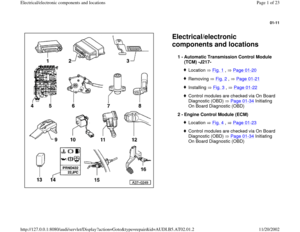
The control module is located in front of the right front seat under the
carpet in the foot well. Fig. 1 Location of automatic Transmission Control Module (TCM)
-J217-
Pa
ge 10 of 23 Electrical/electronic com
ponents and locations
11/20/2002 htt
p://127.0.0.1:8080/audi/servlet/Dis
play?action=Goto&t
yp
e=re
pair&id=AUDI.B5.AT02.01.2
Page 11 of 23
01-21
Removing
Repair Manual, Body
-Interior, Repair Group 70
Fig. 2 Automatic Transmission Control Module (TCM) -J217-,
removing and installing
- Remove lower right A-pillar trim and right front door sill trim.
- Detach carpeting from right inside door sill, and raise carpeting approx.
20 cm.
- Unclip box at -A- by pulling it upward.
- Unclip box at -B- as shown.
- Unclip TCM from box (arrows).
- Release catch on multi-pin connector and disconnect connector from
TCM Fig. 3
Pa
ge 11 of 23 Electrical/electronic com
ponents and locations
11/20/2002 htt
p://127.0.0.1:8080/audi/servlet/Dis
play?action=Goto&t
yp
e=re
pair&id=AUDI.B5.AT02.01.2
Page 12 of 23
01-22
Installing:
Install in reverse order of removal, with the
following additional steps:
- Check that clip nut -1- is properly secured.
Connect in reverse order of disconnecting. Fig. 3 TCM -J217-, disconnecting
- Switch ignition off and wait approx. 30 seconds.
- Release connector by pressing catch in direction of arrow.
Pa
ge 12 of 23 Electrical/electronic com
ponents and locations
11/20/2002 htt
p://127.0.0.1:8080/audi/servlet/Dis
play?action=Goto&t
yp
e=re
pair&id=AUDI.B5.AT02.01.2
Page 13 of 23
01-23
Location: in electronics box (E-box) in plenum chamber (left side).
ECM, removing and installing
Repair Manual, Fuel Injection & Ignition, Engine, Groups 01, 23 or 24 Fig. 4 Engine Control Module (ECM)
Pa
ge 13 of 23 Electrical/electronic com
ponents and locations
11/20/2002 htt
p://127.0.0.1:8080/audi/servlet/Dis
play?action=Goto&t
yp
e=re
pair&id=AUDI.B5.AT02.01.2
Page 14 of 23
01-24
Location: Up to m. y. 2000, the Data Link Connector (DLC) is located
under the rear ashtray (center console).
Fig. 5 Data Link Connector (DLC)
As of m. y. 2001, the DLC is located under the kneebar left of the steering
wheel.
- Connect VAS 5051 tester with VAS5051/1 diagnostic wire, or connect
V.A.G 1551 Scan Tool with VAG 1551/3 adapter.
- Enter address word "02 transmission electronics" and continue
switching until "selecting function XX" appears on display page 01
-
36
.
Pa
ge 14 of 23 Electrical/electronic com
ponents and locations
11/20/2002 htt
p://127.0.0.1:8080/audi/servlet/Dis
play?action=Goto&t
yp
e=re
pair&id=AUDI.B5.AT02.01.2
Page 15 of 23

01-25
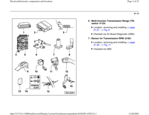
Location: The valve body is bolted to the underside of the transmission
housing inside the oil pan.
The Solenoid Valves -N88-, -N89-, -N90-, -N91-, -N92-, -N93- and -N94-
are attached to the valve body. The solenoid valves -N91-, -N92-, -N93-
and -N94- are also referred to as pressure control valves 1 (-N215-), 2 (-
N216-), 3 (-N217-) and 4 (-N218-).
Removing and installing
Repair Manual, 5 Spd. Automatic Transmission 01V, Repair Group 38
There are two types of transmissions:
Information about which transmission is installed:
Repair Manual, 5 Spd. Automatic Transmission 01V, Repair Group 00 Fig. 6 Valve body
For transmissions with hydraulic regulation -E17-, the transmission
input speed sensor (inductive sensor) is secured to the underside of
the valve body. For transmissions with hydraulic regulation -E18/2-, the transmission
input speed sensor (camshaft position sensor) is secured behind valve
body at transmission housing.
Pa
ge 15 of 23 Electrical/electronic com
ponents and locations
11/20/2002 htt
p://127.0.0.1:8080/audi/servlet/Dis
play?action=Goto&t
yp
e=re
pair&id=AUDI.B5.AT02.01.2
Page 16 of 23
01-26
Location: The wiring harness is secured to the valve body.
The wiring harness can be removed with the valve body removed and the
transmission installed.
Wiring harness in transmission, removing and installing
Repair Manual, 5 Spd. Automatic Transmission 01V, Repair Group 38
ATF Temperature Sensor -G93-, removing and installing
Repair Manual, 5 Spd. Automatic Transmission 01V, Repair Group 38 Fig. 7 Wiring harness with integrated Transmission Fluid
Temperature Sensor -G93-
Pa
ge 16 of 23 Electrical/electronic com
ponents and locations
11/20/2002 htt
p://127.0.0.1:8080/audi/servlet/Dis
play?action=Goto&t
yp
e=re
pair&id=AUDI.B5.AT02.01.2


-J217-
Pa
ge 10 of 23")
 -J217-,
removing and installing
- Remove lower right A-pillar trim and")

 in plenum chamber (left side).
ECM, removing and installing
Repair Manual, Fuel Injection & Ignition, Engine, Groups 01, 23 or 24 Fig. 4 Eng")
 is located
under the rear ashtray (center console).
Fig. 5 Data Link Connector (DLC)
As of m. y. 2001, the D")
