Page 273 of 421

Body and Trim
Roof Seals - Adjustment
9.2.01.6 - Roof
Seals
- Adjustment
Seal adjustment is done in two stages. First stage -
lateral adjustment, and second stage - outward
adjustment. Seals are packed out using selected
packing strips.
Lateral Adjustment
Partially open the roof.
Front frame seal only: Remove the seal retaining
plate.
Remove the seal from the channel.
Slacken the channel securing screws and reposition
the channel as required, moving it on the slotted
screw holes (Fig 3-A). Tighten the channel securing
screws.
Apply soft soap to the seal and insert the outer seal
edge into the channel. Then press in the inner edge
to fully seat the
seal.
Refit the seal retaining plate.
Outward Adjustment
Partially open the roof.
Remove the seal retaining plate. Remove the seal
from the channel. Mark the position of the channel
for reference, release the screws and remove the
channel.
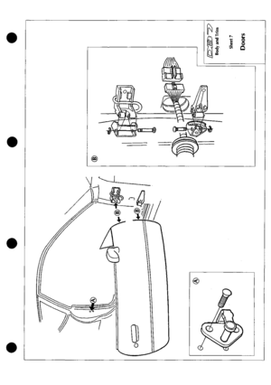
Select the appropriate packing (Figure 3-B)(see
DB7 Volante parts manual):
Rear frame seal foam strip
Front frame seal foam strip
Main column seal foam strip
Upper 'A' post seal foam strip
Note: The foam strips are for full length packing. For
packing at one end
only,
a shorter rubber
wedge
can be
used. (Fig 1-C)
Fit the foam strip/rubber wedge and channel. Align
the channel in the previously marked position. Fit
and tighten the securing screws.
Apply soft soap to the seal and insert the outer seal
edge into the channel. Then press in the inner edge
to fully seat the
seal.
Refit the seal retaining plate.
Note: It is imporrtant at all times to retain the overall
shapeoftheroofsealline(Fig4).
Wherea
leak necessitates
the
adjustment of only
one
or two
seals,
ensure
that
there
are
no
misalignments.
A more
satisfactory result
may be
obtained by adjusting the adjacent component, i.e. the
door
glass
or rear quarter glass.
The relationship between the roof seals is very
important. Two seals in very close contact will
promote leakage problems. Sealing will be far more
effective ifthe seals touch lightly or exhibit a small
air gap (Fig 4).
Figure 4. Seal Line and spacing
Figure 3. Front Frame Seal Adjustment
7-18 May 1996
Page 274 of 421
^?
Body and Trim
Cheater Panel Seals
9.2.01.7
Renew
Cheater Plate Seals - Adjust/
The contact line along the front edge of the door
glass,
and continuing via the cheater plate, is
critical.
Closer examination of the cheater plate
assembly (following leak path identification) may
reveal ridges where the upper and lower seals are
joined.
(Fig 5). The only solution is to carefully fit
new
seals using an
appropriate sealant
and
contact
adhesive.
Figure
5.
Cheater Panel Seals
If the leak is caused by incorrect positioning of the
door glass, carry out the adjustment procedure as
detailed in 9.2.01.8.
May 1996 7-19
Page 275 of 421

Body and Trim
Door Glass Adjustment ^?
9.2.01.8 - Door Glass Adjustment
The door glass can be adjusted in three planes. Lateral, Up and Down, and Front to Rear. It is advisable however
to avoid forward and rearward adjustment if possible,
as
this will affect the height and overall position of
the
glass
relative to the seals. Use this adjustment only to correct serious misalignment.
Lateral Adjustment
Remove the door trim pad. Partially lower the window to allow access to the glass channel mounting bracket (Fig
6-A). Slacken off the four nuts to allow lateral adjustment. Move the glass to the desired position and tighten the
nuts.
Close the
window
and
recheck the alignment.
Repeat the
adjustment until
the
optimum alignment
is
achieved.
Refit the door trim pad.
Upward Adjustment
Remove the door trim pad. Slacken off the regulator locknut (Fig 6-B). With the door
closed,
operate the window
to the fully closed position and tighten the locknut. Refit the door trim panel.
Front to Rear Adjustment
Remove the door trim pad. Partially lower the window to allow access to the glass channel mounting bracket (Fig
6C).
Slacken
the
four
screws
to allow
glass
movement.
Move
theglass
to the
required position
and tighten
the screws.
Close the window and recheck the alignment. Repeat the adjustment as necessary until the optimum front to rear
alignment is achieved. Refit the door trim pad.
Figure
6. Door
Class Adjustments
7-20 May 1996
Page 276 of 421

"^7
Body and Trim
Cleaning of Alcantara Trim
Cleaning of Alcantara Trimmed Roof Lining and Interior Components
Recommendations
1.
Clean the stain immediately.
Clean the stain working from the edge to the centre of the spot to prevent a ring forming.
Delicately remove most of the dirt with a blunt scraper and immediately blot the spot with a clean white cloth.
Once you've identified the type of stain, follow the instructions in the spot removal chart.
Never pour a solvent directly on the spot; instead pour the solvent on a clean cloth.
After you've applied the spot remover, remove it with a dry clean cloth. Afterwards, brush the area against the
material nap.
7. Let the spot dry. Do not sit on a humid part. Afterwards, vacuum the spot with a vacuum cleaner.
Spot Removal Chart
Type of
Stain
Alcohol-Liquors
Beer
Coffee, Tea, Milk
Chocolate, Confectionary
Paints
Cosmetics
Grass, Plants
Chewing Gum
Ink
Marmalade, Syrup, Fruit Juice
Oil,
Grease
Ballpoint Pen
Wine Beverages
Cleaning Product and
Cleaning Method
Wash with mild soap, then blot with denatured alcohol
Blot with lukewarm water (max 50°C) and denatured alcohol at 3%
Washwithmildsoap. If the stain persists, blot with denatured alcohol or ammonia diluted
at 10%.
Blot with lukewarm water (max 50°C) or with ammonia diluted at 5%.
Oil Paint - Blot with ethyl alcohol then wash with mild soap.
Water Based Paint - If the stain is fresh, blot with cold water. An old stain is very difficult
to remove, consult a specialist.
Apply ethyl alcohol or perchloroethylene, then wash with mild soap. If the stain persists,
use ammonia diluted at 5% or denatured alcohol.
Blot with lukewarm water (max 50°C) then wash with mild soap.
Blot with acetone.
Remove as much as possible with a paper towel. Blot with a solution of 30% denatured
alcohol and 70% water, then wash with mild soap. Lemon juice also gives good results.
Blot with lukewarm water (max 50°C). If the stain persists, use ethyl alcohol or
perchloroethylene
Blot with denatured alcohol, then wash with mild soap.
Blot with perchloroethylene and denatured alcohol.
Blot with water and vinegar (50%), then wash with mild soap.
May 1996 7-21
Page 277 of 421
Body and Trim
in:m^^'T?
7-22 May 1996
Page 278 of 421

in:!M3^^?
Air Conditioning
Contents
Contents
General Description 8-5
Specifications 8-5
Climate Control System 8-6
System Description 8-7
Special Servicing Tools and Equipment 8-7
Working Practices 8-8
General 8-8
Handling Refrigerant 8-8
Handling Lubricating Oil 8-8
System Maintenance 8-8
Temperature Distribution System 8-9
Fan Speed Control (Mode Switch) 8-10
Face Level Temperature Differential 8-10
Temperature Rotary Control 8-10
Refrigeration Cycle 8-11
System Protection 8-12
General System Procedures 8-12
Leak Test 8-12
Charge Recovery (System Depressurisation) 8-12
Evacuating the System 8-13
Adding Compressor Lubricating Oil 8-13
Adding Refrigerant 8-14
Functional Check 8-15
System Trouble Shooting 8-1 7
Electronic Control Module (ECM) 8-19
In Car Controls 8-21
Temperature Demand Switch 8-21
Face Level Differential Controller 8-21
Air Conditioning Function Switch 8-22
Fan Speed Control Switch (Mode Switch) 8-23
Temperature Sensors 8-23
Evaporator Sensor 8-24
Motorised In-Car Aspirated Sensor 8-24
Water Temperature Switch 8-25
Blower Motors 8-25
Potentiometers 8-26
Servo Motors 8-27
Vacuum System 8-28
Pressure-Temperature Graphs 8-29
May 1996 8-1
Page 279 of 421

Air Conditioning
Contents '=2?
System Fault Diagnosis
Fault Finding
Blower Motor Test
Open Water Temperature Switch Needs
Short Water Temperature Switch Leads
Refrigeration
Compressors
Compressor Clutch Control
Trinary Switch
Condenser
Receiver-Drier
Evaporator
Expansion Valve
Sanden Compressor SD7H15
Manifold Gauge Set
System Checking with the Manifold Gauge Set
Evacuating the Manifold Gauge Set
Connecting the Manifold Gauge Set
Stabilising the System
Purging the Test Hoses
Leak Test
Manifold Gauge Set Check Procedures
Refrigerant Slightly Low.
Refrigerant Excessively Low.
Air In The System.
Compressor Malfunction
Moisture in the System
A Large Amount of Air in the System.
Expansion Valve Malfunction.
Expansion Valve Malfunction
Restriction in the High Pressure Side.
Torque Levels for the Hose Connections
8-30
8-33
8-33
8-33
8-34
8-35
8-35
8-35
8-35
8-36
8-36
8-36
8-37
8-39
8-39
8-39
8-39
8-40
8-40
8-41
8-41
8-42
8-42
8-43
8-44
8-45
8-45
8-46
8-46
8-47
Air Conditioning Procedures
Depressurising
Recovering Refrigerant
Evacuating and Recycling the Refrigerant
Recharging the System
Compressor Oil Check
8-47
8-47
8-48
8-49
8-49
8-2 May 1996
Page 280 of 421

^7
Air Conditioning
Contents
Repair Procedures
8.1.01.1 Compressor Removal/Renewal 8-51
8.1.02.1 Field Coil Renewal 8-52
8.1.03.1 Renew Gasket Kit 8-52
8.1.04.1 Valve Plate Renewal 8-53
8.1.05.1 Expansion Valve Renewal 8-54
8.1.06.1 Hose-Compressor to Evaporator Renewal 8-55
8.2.01.1 Air Conditioning Unit Renewal 8-55
8.2.02.1 Evaporator Unit Renewal 8-56
8.2.03.1 Upper Servo Feedback Potentiometer Renewal 8-57
8.2.04.1 Lower Servo Feedback Potentiometer Renew 8-57
8.2.05.1 Upper Flap Motor Assembly Renew 8-58
8.2.06.1 Lower Flap Motor Assembly Renew 8-58
8.2.07.1 Ambient Temperature Sensor Renew 8-59
8.2.08.1 Blower Motor Driver Side Renewal 8-59
8.2.09.1 Blower Motor Passenger Side Renewal 8-59
8.2.10.1 Blower Assembly Driver/Passenger Side Overhaul 8-60
8.2.11.1 Blower Motor High Speed Relay Renewal 8-61
8.2.12.1 Water Temperature Switch Renewal 8-62
8.2.13.1 Heater Matrix Renewal 8-62
8.2.14.1 Electronic Control Module Renew 8-63
8.3.01.1 Vacuum System Solenoid Renewal 8-63
May 1996 8-3