Page 25 of 421
[EM^^^
Electrics
Barometric Pressure Sensor
6.7.07
Barometric Pressure Sensor -
Renew
Data
Torque Figures
Sensor mounting nut 2-3 Nm
Procedure
1.
Disconnect the battery.
2.
Remove the left rear quarter trim panel to access the
TCM and barometric pressure sensor.
Figure 1
3. Disconnect the harness multi plug (Fig. 1-3) from
the barometric pressure sensor (Fig.
1
-4 ).
4.
Release the two securing clips (Fig. 1-5) and
remove the sensor).
5. Fitthe new sensor into position, and secure with the
two clips.
6. Connect the multi
plug.
7. Refit the interior
trim.
8. Reconnect the battery.
May 1996 6-17
Page 26 of 421

Electrics
Electrical Component Location and Wiring Information in::m3^?
DB7 Electrical Component Location and
Wiring Information
Thefol lowing pages contains electrical component
location and electrical wiring diagrams.
Component Index
The following list details all of the functional
electrical components of the DB7. The list is given
in alphabetical order with component location and
wiring diagram references for each component.
Component Location on the vehicle
To locate a component on the veh
icie,
find its name
in the component index and note the component
location reference.
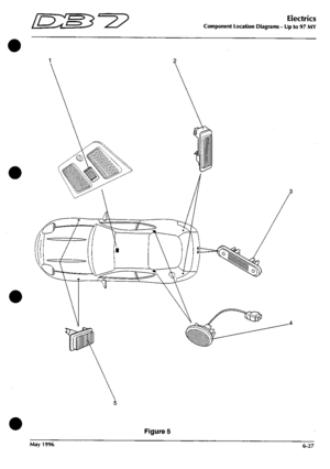
The component location reference gives the figure
number and item number for each component so
that you can find the component on the following
location diagrams and in the car.
Component Location on the Wiring Diagrams
The wiring diagram reference gives the wiring
diagram number and the location coordinates so
that you can locate the component and its wiring
on the wiring diagrams.
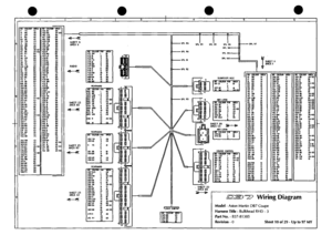
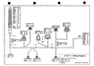
Wiring Diagrams
Each diagram covers a complete loom or section of
a major loom.
Continuations of a loom on another sheet and
connections to other looms are indicated by the
continuation arrow »* and the Sheet Number and
Co-Ordinateswherethecontinuation or connection
is located.
Each connector is illustrated with an end view of
the mating face of the connector. A table beside
each connector gives the pin number, wire colour
and destination of each wire.
Wire Colours
The following key is used to denote wire colours in
the connector wiring tables
B = Black P = Purple G = Green
K = Pink S = Slate LG = Light Green
N = Brown W = White O = Orange
R = Red U = Blue Y = Yellow
Wire Splices
Many wire runs are spliced within the loom
wrapping and additional information is required to
aid in fault analysis. All splices are noted on the
wiring diagrams (e.g. SPL1 = Splice 1). On the
facing page for each wiring diagram, a splice list
gives the splice number and the wire colours and
destinations for each wire coming from the splice.
6-18 May 1996
Page 27 of 421

Electrics
Electrical Component Location Index - Up to 97 MY
Component Name
ABS ECU
Air Con Compressor Clutch
Air Con Fan Motor - LH
Air Con Fan Motor - RH
Air Conditioning Trinary Switch
Air Conditioning Unit
Air Pump
Air Temperature Sensor
Alarm Override Switch
Alarm Siren
Alternator
Ambient Temperature Sensor
Barometric Pressure Sensor
Boot Lamp
Boot Lamp
Boot Lock Actuator
Boot Release Switch
Brake Accumulator Pump
Bulb Fail Unit - Front Side Lights
Camshaft Sensor
Central Locking Unit
Cigar Lighter
Column Switchgear
Crankshaft Position Sensor
Cruise Control Brake Switch
Cruise Control Clutch Switch (LHD)
Cruise Control ECU
Cruise Control On/Off Switch
Cruise Control Pump
Cruise Control Set Switch
Cruise Control Inhibit Switch
Diagnostic Socket - Transmission
Dimmer Module
Door Lock Actuator
Door Mirror- LHD
Door Mirror- RHD
Door Mirror Switch LH
Door Mirror Switch RH
Door Speaker -LH
Door Speaker - RH
EDIS Coil Pack
EDIS Amplifier Module
Engine Diagnostic Socket
Engine ECU
Exhaust Temperature/Speed Warning
Fan Fuses
Fan Motor 1
Fan Motor 2
Fan Run-on Switch
Flasher Module
Fog Lamp - RH Front
Fog Lamp - LH Front
Location
Reference
15-1
3-20
8-2
8-6
10-6
8-3
8-4
3-13
1-8
11-7
3-2
1-12
11-1
5-2
5-2
13-8
2-10
7-4/8
4-6
3-10
9-4
8-1
13-3
3-3
11-8
12-9
6-3
12-7
1-2
12-8
10-8
10-7
4-16
12-12
2-4
2-8
2-3
2-9
6-4
6-9
3-1
1-10
10-5
7-3
4-3
1-21
7-6
7-7
7-5
4-13
14-10
14-9
Wiring Diag.
Reference
28-A1
5-D2
8-A5
13-C4
5-D3
11-82
1-C2
5-C3
1-C5
1-B3
5-D3
1-A2
4-A4
24-A5
24-C4
27-A5
l-i-C3
28-84
9-C2
6-C3
8-D1
19-D3
12-C5
5-D2
12-85
2-D4
20-A2
20-C3
2-A3
20-D3
21-D3
12-A4
13-A4
17/18-B1
17-A3
17-A5
17-D5
18-D5
17-C5
18-C5
5-D5
6-B2
6-D4
6-C5
11-C5
3-A3
3-A2
3-B2
5-A2
13-C2
1-A1
1-C1
Rep.
Op. Notes
Reference
5.1.11.1
8.1.07.3
8.2.09.1
8.2.08.1
8.1.11.1
8.2.01.1
2.3.01.2
2.2.06.1
6.1.06.1
6.2.03.1
6.3.01.1
8.2.07.1
3.3.08.2
6.9.04.1
6.9.04.1
6.9.06.1
6.5.09.1
5.1.08.1
6.4.01.1
2.5.06.1
6.7.03.1
6.5.10.1
6.5.02.1
2.5.06.3
6.4.02.1
6.1.08.1 Manual only
6.6.09.1
6.5.07.1
6.1.09.2
6.5.07.2
3.3.08.6
6.4.03.1
6.4.04.1
6.7.10.1
6.7.08.1
6.8.01.1
6.7.08.2
6.8.01.2
6.7.09.1
6.8.02.1
6.2.05.1
6.2.05.3
6.4.05.1
6.4.06.1
6.4.07.1 Multi-functio
6.2.06.1
1.7.17.1
1.7.17.2
1.7.16.4
6.4.08.1
6.1.04.1
6.1.04.2
May 1996 6-19
Page 28 of 421

Electrics
Electrical Component Location Index •
Component Name
Fuel Filler Flap Solenoid
Fuel Pump 1
Fuel Pump 2
Fuel Tank Sender Unit
Gear Selector Illumination
Gear Shift Interlock Solenoid
Gearbox Connector (Auto)
Gearbox ECU
Gearshift Interlock Module
Handbrake Switch
Headlamp Control Module
Head/Side Lamp - LH Front
Head/Side Lamp - RH Front
Heated Front Screen Controller
Heated Front Screen Fuse - 40A
Heated Front Screen
Heated Front Screen
Heated Rear Screen
Heated Washer Jet
Heated Washer Jet
High Level Stop Lamp
Horn - LH
Horn - RH
Idle Speed Control Valve
Ignition Switch
Indicator/Side Lamp - LH Front
Indicator/Side Lamp - RH Front
Inertia Switch
Injector 1
Injector 2
Injector 3
Injector 4
Injector 5
Injector 6
Input Speed Sensor (Auto)
Instrument Panel Illumination Control
Instrument Panel
Interior Light - Rear LH
Interior Light - Rear RH
Key Solenoid
Key-In Warning Switch
Kickdown Switch
Lambda Sensor A
Lambda Sensor B
Logic Earth
Low Coolant Probe
Low Level Sensor
Lumbar Pump
Map Reading Light
Microswitch - Glass Drop LH
Microswitch - Glass Drop RH
Up to 97 MY
Location
Reference
2-1
15-13
15-14
15-12
9-3
13-6
7-11
11-2
13-7
8-8
1-3
14-7
14-12
11-4
11-5
7-10
7-1
9-8
1-11
1-11
9-1
11-6
11-6
3-17
8-7
14-8
14-11
7-2
3-6
3-7
3-8
3-9
3-n
3-12
11-11
2-7
2-6
5-4
5-4
11-10
11-9
8-5
3-18
3-19
9-2
13-5
4-1
9-5
5-1
12-2
12-2
Wiring Diag.
Reference
24-A3
25-A1
25-A2
24-C5
19-D4
21-C4
7-B4
4-B3
21-A2
24-A1
2-A2
1-D2
1-A2
9-A2
9-B2
8-B5
14-B2
24-A2
5-A3
5-B3
24-B2
3-C1
3-81
5-C5
12-D2
1-C1
1-A1
8-D2
5-A2
5-C2
5-A3
5-C2
5-A4
5-C4
7-B2
13-D5
11-C5
24-A2
24-D2
12-B2
12-B2
14-A5
6-B5
6-B5
10-D4
8-C3
3-C1
22-D2
13-C4
17-A2
18-A2
Ini^'
IL-^^'^
Rep.
Op.
Reference
6.9.07.1
2.6.02.1
2.6.02.1
2.6.06.1
6.5.11.1
3.3.01.1
6.6.10.1
6.5.12.1
6.1.10.1
6.1.01.1
6.1.01.2
6.4.09.1
6.4.09.2
6.4.09.3
6.4.09.3
6.6.11.1
6.4.10.1
6.4.10.1
6.6.12.1
6.1.11.1
6.1.11.1
2.2.05.1
6.5.13.1
6.1.03.1
6.1.03.1
6.5.14.1
6.3.04.1
6.3.04.1
6.3.04.1
6.3.04.1
6.3.04.1
6.3.04.1
3.4.02.1
6.5.04.2
6.5.04.1
6.6.02.1
6.6.02.1
6.5.14.1
5.4.01.1
6.3.05.1
6.3.05.1
6.5.15.1
1.7.14.1
6.6.01.1
6.1.13.1
6.1.13.1
W3^y
Notes
Auto only
Auto only
Auto only
Auto only
Auto only
Auto only
Auto only
6-20 May 1996
Page 29 of 421

[n:m3^y
Component Name
Microwave Sensor
Mode Switch
Multifunction Module
Number Plate Lamp - LH
Number Plate Lamp - RH
Oil Pressure Warning Light Transducer
Output Speed Sensor (Auto)
Park Switch (Auto)
Purge Valve 1
Purge Valve 2
Radio Aerial
Radio Telephone Connector
Radio Tweeter
Radio Tweeter
Radio
Rear & Number Plate Bulb Fail Unit
Rear Fog Lamp LH
Rear Fog Lamp RH
Rear Lamp - LH
Rear Lamp - RH
Recline Motor Potentiometer
Relay - ABS Pump
Relay - Air conditioning clutch
Relay - Air Pump
Relay - Auxiliary Load
Relay - Boot Release
Relay - Courtesy Lights
Relay - Cruise Control On/Off
Relay - Drivers Seat Heater
Relay - Fan 1
Relay - Fan 2
Relay - Fan Run On
Relay - Front Fog Lamps
Relay - Fuel Pump 1
Relay - Fuel Pump 2
Relay - Gearbox Failure Warning
Relay - Headlamp Dipped Beam
Relay - Headlamps
Relay - Heated Rear Window
Relay - Horns
Relay - Ignition Load
Relay - Main
)
Location
Reference
12-1
7-9
4-2
5-3
5-3
3-17
11-12
10-1
10-3
10-4
15-4
15-3
6-7
6-5
6-6
15-11
14-2
14-5
14-1
14-6
9-7
4-8
1-17
4-14
4-4
15-9
4-11
6-1
12-3
1-20
1-19
1-18
1-6
15-7
15-8
4-9
1-5
1-7
4-15
1-16
4-10
4-12
Relays - Drivers/Passengers Seat Heaters 12-3
Relay - Rear Fog Lamps
Relay - Reverse Lamps
Relay - Sidelamps
Relay - Starter Solenoid
Relay - Stop Lamps
Reversing Lamp Switch (Man)
Reversing Light Switch (Auto)
Screen Wash Pump
4-17
15-6
1-9
1-15
15-5
11-3
10-2
1-13
Electrics
Electrical Component Location Index - Up to 97 MY
Wiring Diag.
Reference
24-C2
4-A3
8-C4
27-84
27-B6
5-C5
7-B3
21-B1
5-A4
5-A5
24-D2
25-B2
8-C3
14-C4
10-A2
25-C3
17-D2
18-D2
24-A5
24-C4
22-81
9-C4
3-A3
13-A5
9-D1
26-D3
13-A2
20-B1
16-D3
3-B6
3-B6
3-A5
1-B5
26-A2
26-A3
13-A1
1-B5
1-84
13-A4
3-A4
13-A2
13-A3
15-D3
13-A5
25-A4
1-B4
3-A4
25-A5
7-C5
21-C2
3-D1
Rep.
Op. Notes
Reference
6.6.14.2
6.5.07.4
6.4.12.1
6.9.03.1
6.9.03.1
1.5.08.1
3.4.02.2
Auto only
6.5.13.1
Auto only
6.1.14.1
6.1.14.2
6.9.08.1
6.9.09.1
6.5.17.1
6.5.17.1
6.5.05.1
6.9.10.1
6.7.02.1
6.6.07.1
5.1.15.1
6.2.06.1
6.4.13.1
6.4.14.1
6.9.11.1
6.4.15.1
6.5.18.1
6.6.15.1
1.7.16.3
1.7.16.3
1.7.16.4
6.1.04.3
6.9.12.1
6.9.12.1
6.4.16.1
Auto only
6.1.15.1
6.1.16.1
6.4.17.1
6.2.07.1
6.4.18.1
6.4.19.1
6.6.15.2
6.4.20.1
6.9.13.1
6.1.17.1
6.2.08.1
6.9.14.1
6.2.09.1
6.2.09.2
6.3.06.1
May 1996 6-21
Page 30 of 421

Electrics
Electrical Component Location Index - Up to 97 MY
Component Name
Seat Belt Switch
Seat ECU - Driver
Seat ECU - Passenger
Seat Heater - Cushion Element
Seat Heater - Squab Element
Seat Heater Control Module
Seat Motor Potentiometer
Seat Pressure Pad
Seat Switch Pack - Driver
Seat Switch Pack - Passenger
Security System Aerial
Security System ECU
Side Marker Lamp - LH Front
Side Marker Lamp - RH Front
Speaker - Rear LH
Speaker - Rear RH
Speed Control Dump Valve
Start Inhibit Switch
Starter Motor Solenoid
Stop Lamp Fail
Stop Lamp/Cruise Disable Switch
Thermal Breaker - Window Lift
Throttle Potentiometer
Water Temp Sensor - Engine ECU
Water Temp Sensor - Temp Gauge
Wheel Speed Sensor - Front RH
Wheel Speed Sensor - Front LH
Wheel Speed Sensor - Rear RH
Wheel Speed Sensor - Rear LH
Window ECU - LH
Window ECU - RH
Window Switch - RH
Window Switch LH
Wiper Logic Module
Wiper Motor
Window Lift Motor
Location
Reference
13-2
6-2
6-2
12-5
12-4
6-3
9-7
12-6
6-8
6-8
2-12
15-2
5-5
5-5
6-10
6-10
1-4
10-9
3-14
15-10
11-8
4-7
3-15
3-5
3-4
13-4
13-4
13-1
13-1
12-11
12-11
2-5
2-5
4-5
1-1
12-10
Wiring Diag.
Reference
22-A3
16-A1
15-A1
22-A2
15/16-A4
22-A5
22-C2
22-D3
16-B1
15-B1
24-C2
26-B6
1-C2
1-A3
24-B2
24-C2
2-A2
21-C3
3-C2
25-A3
12-C5
9-C3
5-A3
5-C2
5-C2
29-C3
28-D4
28-D3
28-D2
17-D3
18-D3
19-A2
19-D2
9-A3
8-C3
Rep.
Op.
Reference
6.6.16.1
6.6.17.1
6.6.17.2
6.6.18.1
6.6.18.2
6.6.18.3
6.6.19.1
6.6.20.1
6.6.21.1
6.6.21.1
6.6.22.1
6.6.22.3
6.1.18.1
6.1.18.1
6.6.23.1
6.6.23.1
6.1.19.1
6.1.20.1
6.3.02.2
6.9.15.1
6.4.02.1
6.1.21.1
2.5.02.2
6.3.07.1
8.2.12.1
5.1.12.1
5.1.12.1
5.2.01.1
5.2.01.1
6.1.22.1
6.1.22.1
6.5.03.1
6.5.03.1
6.2.01.1
6.1.21.3
Notes
6-22 May 1996
Page 31 of 421
/E^S^-^T?
Electrics
Component Location Diagrams - Up to 97 MY
21 20 19 18 17 16 15
Figure 1
May 1996 6-23
Page 32 of 421
Electrics
Component Location Diagrams - Up to 97 MY
m.
CM
3 O
6-24 May 1996