Page 522 of 1503

Radiator
Engine Coolan t Refillin g an d Bleedin g (cont'd)
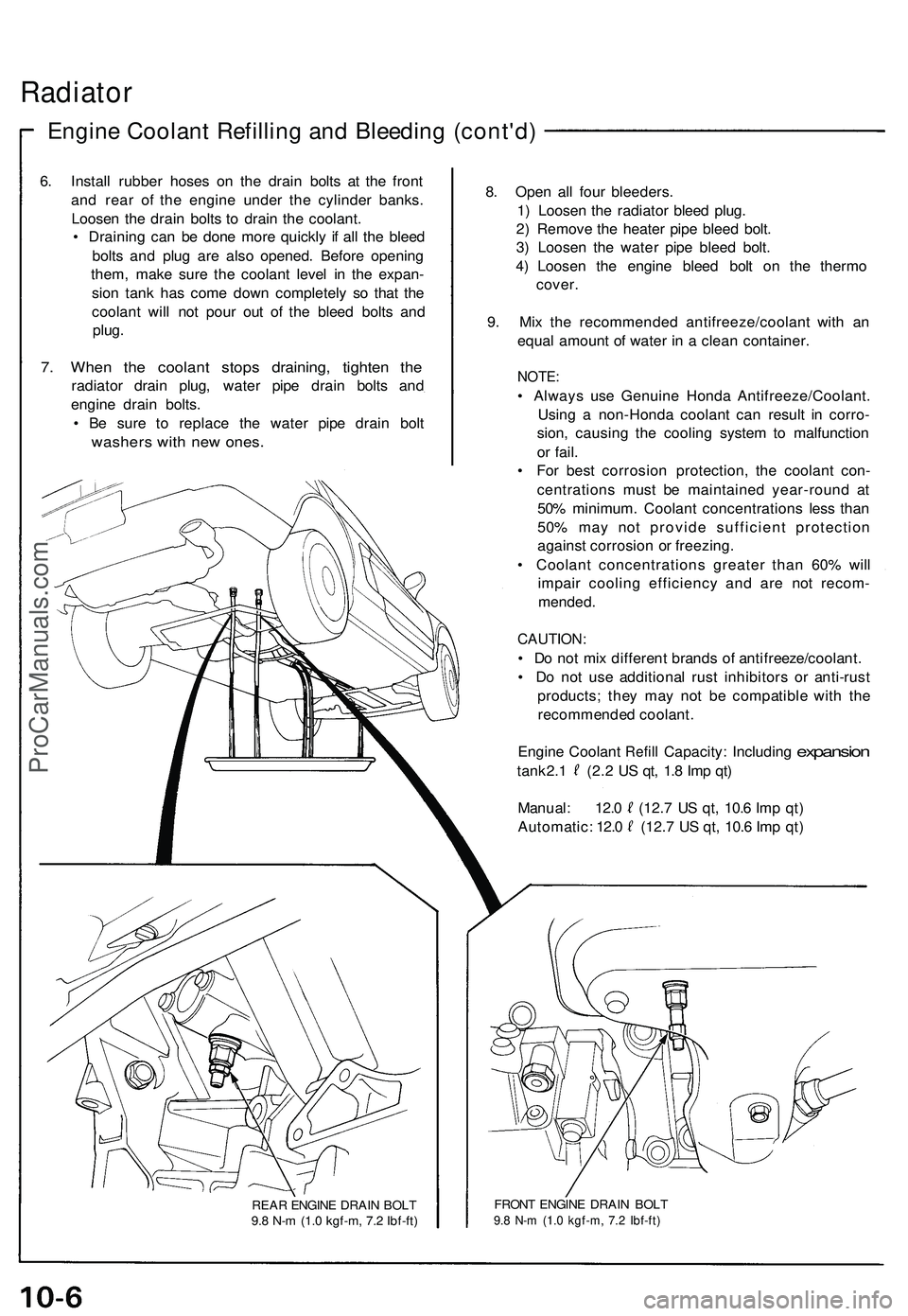
6. Instal l rubbe r hose s o n th e drai n bolt s a t th e fron t
an d rea r o f th e engin e unde r th e cylinde r banks .
Loose n th e drai n bolt s t o drai n th e coolant .
• Drainin g ca n b e don e mor e quickl y i f al l th e blee d
bolt s an d plu g ar e als o opened . Befor e openin g
them , mak e sur e th e coolan t leve l i n th e expan -
sio n tan k ha s com e dow n completel y s o tha t th e
coolan t wil l no t pou r ou t o f th e blee d bolt s an d
plug .
7. Whe n th e coolan t stop s draining , tighte n th e
radiato r drai n plug , wate r pip e drai n bolt s an d
engin e drai n bolts .
• B e sur e t o replac e th e wate r pip e drai n bol t
washer s wit h ne w ones .
REAR ENGIN E DRAI N BOL T
9. 8 N- m (1. 0 kgf-m , 7. 2 Ibf-ft )
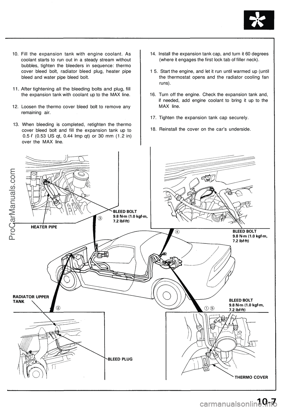
8. Ope n al l fou r bleeders .
1 ) Loose n th e radiato r blee d plug .
2 ) Remov e th e heate r pip e blee d bolt .
3 ) Loose n th e wate r pip e blee d bolt .
4 ) Loose n th e engin e blee d bol t o n th e therm o
cover .
9 . Mi x th e recommende d antifreeze/coolan t wit h a n
equa l amoun t o f wate r i n a clea n container .
NOTE:
• Alway s us e Genuin e Hond a Antifreeze/Coolant .
Usin g a non-Hond a coolan t ca n resul t i n corro -
sion , causin g th e coolin g syste m to malfunctio n
o r fail .
• Fo r bes t corrosio n protection , th e coolan t con -
centration s mus t b e maintaine d year-roun d a t
50 % minimum . Coolan t concentration s les s tha n
50 % ma y no t provid e sufficien t protectio n
agains t corrosio n o r freezing .
• Coolan t concentration s greate r tha n 60 % wil l
impai r coolin g efficienc y an d ar e no t recom -
mended .
CAUTION :
• D o no t mi x differen t brand s o f antifreeze/coolant .
• D o no t us e additiona l rus t inhibitor s o r anti-rus t
products ; the y ma y no t b e compatibl e wit h th e
recommende d coolant .
Engin e Coolan t
Refill Capacity : Includin g expansion
tank 2. 1 (2. 2 U S qt , 1. 8 Im p qt )
Manual : 12. 0 (12. 7 U S qt , 10. 6 Im p qt )
Automatic : 12. 0 (12. 7 U S qt , 10. 6 Im p qt )
FRON T ENGIN E DRAI N BOL T9.8 N- m (1. 0 kgf-m , 7. 2 Ibf-ft )
ProCarManuals.com
Page 523 of 1503

10. Fill the expansion tank with engine coolant. As
coolant starts to run out in a steady stream without
bubbles, tighten the bleeders in sequence: thermo
cover bleed bolt, radiator bleed plug, heater pipe
bleed and water pipe bleed bolt.
11. After tightening all the bleeding bolts and plug, fill
the expansion tank with coolant up to the MAX line.
12. Loosen the thermo cover bleed bolt to remove any
remaining air.
13. When bleeding is completed, retighten the thermo
cover bleed bolt and fill the expansion tank up to
0.5
(0.53
US qt,
0.44
Imp qt) or 30 mm
(1.2
in)
over the MAX line.
14. Install the expansion tank cap, and turn it 60 degrees
(where it engages the first lock tab of filler neck).
1 5. Start the engine, and let it run until warmed up (until
the thermostat opens and the radiator cooling fan
runs).
16. Turn off the engine. Check the expansion tank and,
if needed, add engine coolant to bring it up to the
MAX line.
17. Tighten the expansion tank cap securely.
18. Reinstall the cover on the car's underside.ProCarManuals.com
Page 526 of 1503
Water Pum p
Illustrate d Inde x
NOTE : Us e ne w O-ring s an d ne w specia l bolt s whe n
reassembling .
RADIATOR FA N
CONTRO L SENSO R
2 7 N- m (2. 8 kgf-m ,
2 0 Ibf-ft )
8 x 1.2 5 mm22 N- m (2. 2 kgf-m ,
1 6 Ibf-ft ) O-RIN
G
Replace .
O-RING
Replace . COOLAN
T
TEMPERATUR E GAUG E
SENDIN G UNI T9 N- m (0. 9 kgf-m , 7 Ibf-ft )Apply liqui d gaske tto th e threads .
BLEED BOL T9.8 N- m(1.0 kgf-m , 7. 2 Ibf-ft )
CONNECTIN G PIP E
8 x 1.2 5 mm22 N- m (2. 2 kgf-m ,
1 6 Ibf-ft )
WATE R PASSAG E
O-RIN G
Replace .
ENGINE COOLAN T
TEMPERATUR E (ECT )
SWITC H
1 8 N- m (1. 8 kgf-m , 1 3 Ibf-ft )
WATE R PUM P
Inspection , pag e 10-1 1 O-RIN
G
Replace .
SPECIAL BOL T
6 x 1. 0 mm : 7 BOLT S
1 2 N- m (1.2 kgf-m , 8. 7 Ibf-ft )
Replace .
DRAIN BOLT S
9. 8 N- m (1. 0 kgf-m , 7. 2 Ibf-ft )
Us e rubbe r hose s
when draining .
SPECIAL BOL T
8 x 1.2 5 mm : 2 BOLT S
2 2 N- m (2. 2 kgf-m , 1 6 Ibf-ft )
Replace .
DOWELPIN
DOWE L PI N
O-RIN G
Replace .
ProCarManuals.com
Page 714 of 1503

(cont'd)
Description
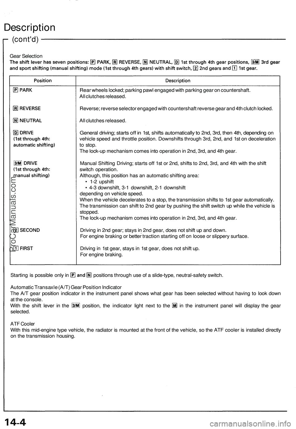
Gear Selection
Starting is possible only in positions through use of a slide-type, neutral-safety switch.
Automatic Transaxle (A/T) Gear Position Indicator
The A/T gear position indicator in the instrument panel shows what gear has been selected without having to look down
at the console.
With the shift lever in the position, the indicator light next to the in the instrument panel will display the gear
selected.
ATF Cooler
With this mid-engine type vehicle, the radiator is mounted at the front of the vehicle, so the ATF cooler is installed directly
on the transmission housing.
Rear wheels locked; parking pawl engaged with parking gear on countershaft.
All clutches released.
Reverse; reverse selector engaged with countershaft reverse gear and 4th clutch locked.
All clutches released.
General driving; starts off in 1st, shifts automatically to 2nd, 3rd, then 4th, depending on
vehicle speed and throttle position. Downshifts through 3rd, 2nd, and 1st on deceleration
to stop.
The lock-up mechanism comes into operation in 2nd, 3rd, and 4th gear.
Manual Shifting Driving; starts off 1st or 2nd, shifts to 2nd, 3rd, and 4th with the shift
switch operation.
Although, this position has an automatic shifting area:
• 1-2 upshift
• 4-3 downshift, 3-1 downshift, 2-1 downshift
depending on vehicle speed.
When the vehicle decelerates to a stop, the transmission shifts to 1st gear automatically.
The transmission can shift to 2nd gear by pushing the shift switch up while the vehicle is
stopped.
The lock-up mechanism comes into operation in 2nd, 3rd, and 4th gear.
Driving in 2nd gear; stays in 2nd gear, does not shift up and down.
For engine braking or better traction starting off on loose or slippery surface.
Driving in 1st gear, stays in 1st gear, does not shift up.
For engine braking.ProCarManuals.com
Page 754 of 1503
ATF Cooler
The radiator is mounted at the front of the vehicle. The ATF cooler is installed directly on the transmission housing. The
ATF is cooled by the engine coolant.ProCarManuals.com
Page 926 of 1503
15. Remove the terminal nuts and the wires from the
gearbox terminals.
Steering Gearbox
Removal/Installation (cont'd)
12. Disconnect the connectors from the EPS wire har-
ness.
16. Remove the radiator pipe bracket at the front com-
partment bulkhead.
17. Remove the radiator pipe bracket at the floor, and
space the radiator pipe away from and gearbox.
13. Remove the ground cable by removing the EPS wire
harness bracket.
14. Remove the terminal guard and ground cable.ProCarManuals.com
Page 927 of 1503
NOTE: Before removing the gearbox, place a stand jack
under the gearbox and front crossbeam to lightly sup-
port them. Lower the gearbox together with the front
crossbeam.
18. Remove the flange bolts and nuts of the gearbox
and front crossbeam.
19. Lower the gearbox and front crossbeam with care
so as not to hit or damage the radiator pipe.
NOTE: The crossbeam is attached to the crossbeam
bracket with locating pins. Remove the crossbeam
by lightly taping on it with a plastic hammer, then
remove the gearbox.
20. When installing the crossbeam to the crossbeam
bracket, be sure to align the holes in the crossbeam
with the locating pins on the crossbeam bracket.ProCarManuals.com
Page 1184 of 1503
Description
Fan Control Unit
The fan control unit performs calculations based on signals from the radiator fan control sensor. It them controls the
operation of radiator fan speed (High-Low), engine compartment fan, condenser fan and A/C compressor.
When engine coolant temperature is above 183°F
(84°C), the fan control unit turns Tr1 ON and
radiator fan runs at low speed.
When engine coolant temperature is above 194°F
(90°C), the fan control unit turns Tr2 ON, and
radiator fan runs at high speed and engine
compartment fan comes on.
When engine coolant temperature is above 266°F
(130°C), the fan control unit turns Tr3 OFF, and
stops the condenser fan. Then it turns Tr4 OFF,
and stops the compressor.
IG2
RADIATOR FAN (Low)
RADIATOR
FAN CONTROL
SENSOR
RADIATOR FAN (High)
ENGINE COMPARTMENT
FAN
CONDENSER FAN
(Right and Left)
ECM
(ACS)
A/C
TRIPLE
PRESSURE
SWITCH
GND
A/C SWITCHProCarManuals.com