1997 ACURA NSX automatic transmission
[x] Cancel search: automatic transmissionPage 374 of 1503

4-5
Y
Do the items in parts A, B, C, D, E, F, and G as required for the mileag\
e/time interval listed.
NOTE: According to state and federal regulations, failure to do the maintenanc\
e items marked with an asterisk (*) will not
void the customer ’s emissions warranties. However, Acura recommends that all maintenance s\
ervices be done at
the recommended interval to ensure long-term reliability.
*1: Refer to the 1997 NSX Service Manual, P/N 61SL006.
*2: Refer to the 1998 NSX Service Manual Supplement, P/N 61SL007.
*3: Refer to the 2001 NSX Service Manual Supplement, P/N 61SW000.
A
B Replace engine oil (see page
8-2)*
2, every 7,500 miles (12,000 km) or 1 year.
Engine oil capacity: without oil filter: 4.3 L (4.5 US qt).
Check tire inflation and condition at least once a month, every 7,500 mi\
les (12,000 km).
Replace engine oil filter (see page 8-5)*1, every 15,000 miles (24,000 km) or 1 year.
Engine oil capacity: with oil filter: 5.0 L (5.3 US qt).
Check front and rear brake wear (see page 19-4)*1, every 15,000 miles (24,000 km) or 1 year.
• Check pads and discs for wear (thickness), damage, and cracks.
• Check calipers for damage, leaks, and tightness of mounting bolts.
Check parking brake adjustment (see page 19-5)*1, every 15,000 miles (24,000 km) or 1 year.
Check the number of clicks (10 to 14) when the parking brake lever is pulled with 196 N (20 kgf,\
44 lbf) of force.
Inspect tie-rod ends, steering gearbox, and gearbox boots (see page 17-57)*1, every 15,000 miles (24,000 km) or 1 year.
• Check rack grease and steering linkage.
• Check boots for damage and leaking grease.
• Check fluid lines for damage and leaks.1
• Check bolts for tightness.
• Check condition of ball joint boots for deterioration and damage.
Inspect driveshaft boots (see page 16-3)*1, every 15,000 miles (24,000 km) or 1 year.
Check boots for cracks and boot bands for tightness.
Inspect brake hoses and lines including ABS (see page 19-27)*1, every 15,000 miles (24,000 km) or 1 year.
Check the master cylinder, proportioning control valve and ABS modulator\
for damage and leakage.
Inspect all fluid levels and condition of fluids, every 15,000 miles (2\
4,000 km) or 1 year.
• Manual transmission fluid (MTF) (see page 13-3)*
1.
• Automatic transmission fluid (ATF-Z1) (see page 14-105)*1.
• Engine coolant (see page 10-2)*1.
• Brake fluid (see page 19-84)*1.
• Windshield washer fluid.
Cooling system hoses and connections (see page 10-2)*1, every 15,000 miles (24,000 km) or 1 year.
• Check all hoses for damage, leaks and deterioration.
• Check for proper fan operation.
Inspect exhaust system (see page 9-6)*, *1, every 15,000 miles (24,000 km) or 1 year.
Check catalytic converter heat shield, exhaust pipe, and muffler for dam\
age, leaks, and tightness ( see page 9-14 ).
Inspect fuel lines and connections (see page 11-130)*, *1, every 15,000 miles (24,000 km) or 1 year.
Check for loose connections, cracks, and deterioration; retighten loose \
connections and replace damaged parts.
Part Maintenance Items
*05-NSX (61SW004)SEC04(01-10) 9/22/04 1:49 PM Page 4-5
Inspect suspension components (see page 18-14)* , every 15,000 miles (24,000 km) or 1 year.
ProCarManuals.com
Page 375 of 1503
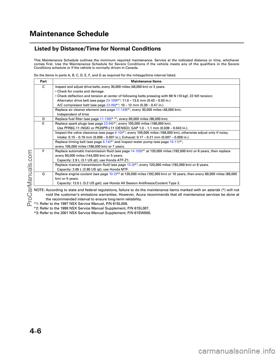
4-6
This Maintenance Schedule outlines the minimum required maintenance. Ser\
vice at the indicated distance or time, whichever
comes first. Use the Maintenance Schedule for Severe Conditions if the v\
ehicle meets any of the qualifiers in the Severe
Conditions schedule or if the vehicle is normally driven in Canada.
Do the items in parts A, B, C, D, E, F, and G as required for the mileag\
e/time interval listed.
NOTE: According to state and federal regulations, failure to do the maintenanc\
e items marked with an asterisk (*) will not
void the customer ’s emissions warranties. However, Acura recommends that all maintenance s\
ervices be done at
the recommended interval to ensure long-term reliability.
*1: Refer to the 1997 NSX Service Manual, P/N 61SL006.
*2: Refer to the 1998 NSX Service Manual Supplement, P/N 61SL007.
*3: Refer to the 2001 NSX Service Manual Supplement, P/N 61SW000.
C
D
E
F
G Inspect and adjust drive belts, every 30,000 miles (48,000 km) or 2 ye\
ars.
•
Check for cracks and damage.
• Check deflection and tension at center of following belts pressing with\
98 N (10 kgf, 22 lbf) tension:
Alternator drive belt (see page 23-109)*
1: 11.0 – 13.5 mm (0.43 – 0.53 in.)
A/C compressor belt (see page 22-88)*1: 10 – 12 mm (0.39 – 0.47 in.)
Replace air cleaner element (see page 11-149)*1, every 30,000 miles (48,000 km).
Independent of time
Replace fuel filter (see page 11-138)*, *1, every 60,000 miles (96,000 km).
Replace spark plugs (see page 23-96)*1, every 105,000 miles (168,000 km).
Use PFR6G-11 (NGK) or PK20PR-L11 (DENSO); GAP 1.0 – 1.1 mm (0.039 – 0.043 in.).
Inspect the valve clearance (see page 6-10)*1, every 105,000 miles (168,000 km), otherwise adjust only if noisy.
Intake: 0.15 – 0.19 mm (0.006 – 0.007 in.), Exhaust: 0.17 – 0.21 mm (0.007 – 0.008 in.).
Replace timing belt (see page 6-14)*1 and inspect water pump (see page 10-11)*1,
every 105,000 miles (168,000 km) or 7 years.
Replace automatic transmission fluid (see page 14-105)*1 at 120,000 miles (192,000 km) or 6 years, then replace
every 90,000 miles (144,000 km) or 5 years.
Capacity: 2.9 L (3.1 US qt); use Honda ATF-Z1.
Replace manual transmission fluid (see page 13-3)*1, every 120,000 miles (192,000 km) or 6 years.
Capacity: 2.65 L (2.80 US qt); use Honda MTF.
Replace engine coolant (see page 10-2 )*3 at 120,000 miles (192,000 km) or 10 years, then every 60,000 miles (9\
6,000
km) or 5 years. Capacity: 12.0 L (3.2 US gal); use Honda All Season Antifreeze/Coolant\
Type 2.
Part Maintenance Items
Maintenance Schedule
Listed by Distance/Time for Normal Conditions
*05-NSX (61SW004)SEC04(01-10) 9/22/04 1:49 PM Page 4-6
ProCarManuals.com
Page 384 of 1503
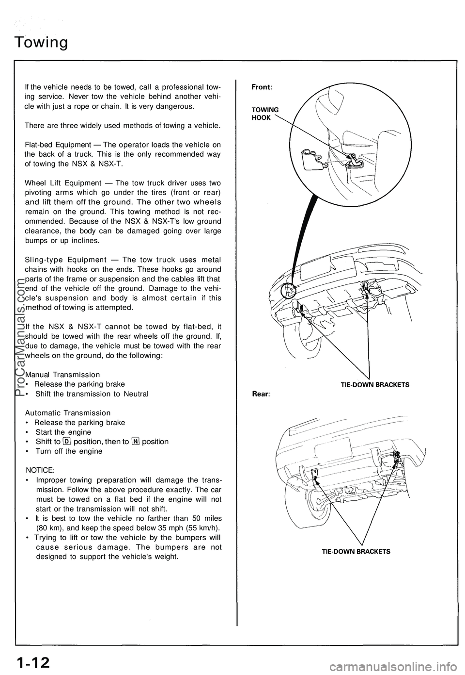
Towing
If the vehicle needs to be towed, call a professional tow-
ing service. Never tow the vehicle behind another vehi-
cle with just a rope or chain. It is very dangerous.
There are three widely used methods of towing a vehicle.
Flat-bed Equipment — The operator loads the vehicle on
the back of a truck. This is the only recommended way
of towing the NSX & NSX-T.
Wheel Lift Equipment — The tow truck driver uses two
pivoting arms which go under the tires (front or rear)
and lift them off the ground. The other two wheels
remain on the ground. This towing method is not rec-
ommended. Because of the NSX & NSX-T's low ground
clearance, the body can be damaged going over large
bumps or up inclines.
Sling-type Equipment — The tow truck uses metal
chains with hooks on the ends. These hooks go around
parts of the frame or suspension and the cables lift that
end of the vehicle off the ground. Damage to the vehi-
cle's suspension and body is almost certain if this
method of towing is attempted.
If the NSX & NSX-T cannot be towed by flat-bed, it
should be towed with the rear wheels off the ground. If,
due to damage, the vehicle must be towed with the rear
wheels on the ground, do the following:
Manual Transmission
• Release the parking brake
• Shift the transmission to Neutral
Automatic Transmission
• Release the parking brake
• Start the engine
• Shift to position, then to position
• Turn off the engine
NOTICE:
• Improper towing preparation will damage the trans-
mission. Follow the above procedure exactly. The car
must be towed on a flat bed if the engine will not
start or the transmission will not shift.
• It is best to tow the vehicle no farther than 50 miles
(80 km), and keep the speed below 35 mph (55 km/h).
• Trying to lift or tow the vehicle by the bumpers will
cause serious damage. The bumpers are not
designed to support the vehicle's weight.ProCarManuals.com
Page 713 of 1503
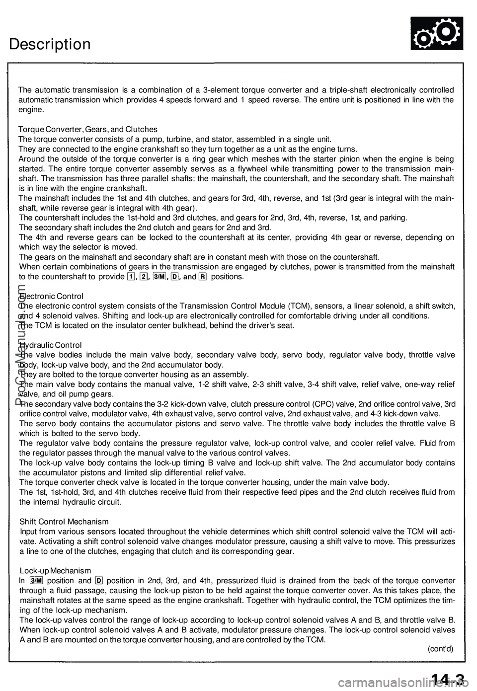
Description
The automatic transmission is a combination of a 3-element torque converter and a triple-shaft electronically controlled
automatic transmission which provides 4 speeds forward and 1 speed reverse. The entire unit is positioned in line with the
engine.
Torque Converter, Gears, and Clutches
The torque converter consists of a pump, turbine, and stator, assembled in a single unit.
They are connected to the engine crankshaft so they turn together as a unit as the engine turns.
Around the outside of the torque converter is a ring gear which meshes with the starter pinion when the engine is being
started. The entire torque converter assembly serves as a flywheel while transmitting power to the transmission main-
shaft. The transmission has three parallel shafts: the mainshaft, the countershaft, and the secondary shaft. The mainshaft
is in line with the engine crankshaft.
The mainshaft includes the 1st and 4th clutches, and gears for 3rd, 4th, reverse, and 1st (3rd gear is integral with the main-
shaft, while reverse gear is integral with 4th gear).
The countershaft includes the 1st-hold and 3rd clutches, and gears for 2nd, 3rd, 4th, reverse, 1st, and parking.
The secondary shaft includes the 2nd clutch and gears for 2nd and 3rd.
The 4th and reverse gears can be locked to the countershaft at its center, providing 4th gear or reverse, depending on
which way the selector is moved.
The gears on the mainshaft and secondary shaft are in constant mesh with those on the countershaft.
When certain combinations of gears in the transmission are engaged by clutches, power is transmitted from the mainshaft
to the countershaft to provide positions.
Electronic Control
The electronic control system consists of the Transmission Control Module (TCM), sensors, a linear solenoid, a shift switch,
and 4 solenoid valves. Shifting and lock-up are electronically controlled for comfortable driving under all conditions.
The TCM is located on the insulator center bulkhead, behind the driver's seat.
Hydraulic Control
The valve bodies include the main valve body, secondary valve body, servo body, regulator valve body, throttle valve
body, lock-up valve body, and the 2nd accumulator body.
They are bolted to the torque converter housing as an assembly.
The main valve body contains the manual valve, 1-2 shift valve, 2-3 shift valve, 3-4 shift valve, relief valve, one-way relief
valve, and oil pump gears.
The secondary valve body contains the 3-2 kick-down valve, clutch pressure control (CPC) valve, 2nd orifice control valve, 3rd
orifice control valve, modulator valve, 4th exhaust valve, servo control valve, 2nd exhaust valve, and 4-3 kick-down valve.
The servo body contains the accumulator pistons and servo valve. The throttle valve body includes the throttle valve B
which is bolted to the servo body.
The regulator valve body contains the pressure regulator valve, lock-up control valve, and cooler relief valve. Fluid from
the regulator passes through the manual valve to the various control valves.
The lock-up valve body contains the lock-up timing B valve and lock-up shift valve. The 2nd accumulator body contains
the accumulator pistons and limited slip differential relief valve.
The torque converter check valve is located in the torque converter housing, under the main valve body.
The 1st, 1st-hold, 3rd, and 4th clutches receive fluid from their respective feed pipes and the 2nd clutch receives fluid from
the internal hydraulic circuit.
Shift Control Mechanism
Input from various sensors located throughout the vehicle determines which shift control solenoid valve the TCM will acti-
vate. Activating a shift control solenoid valve changes modulator pressure, causing a shift valve to move. This pressurizes
a line to one of the clutches, engaging that clutch and its corresponding gear.
Lock-up Mechanism
In position and position in 2nd, 3rd, and 4th, pressurized fluid is drained from the back of the torque converter
through a fluid passage, causing the lock-up piston to be held against the torque converter cover. As this takes place, the
mainshaft rotates at the same speed as the engine crankshaft. Together with hydraulic control, the TCM optimizes the tim-
ing of the lock-up mechanism.
The lock-up valves control the range of lock-up according to lock-up control solenoid valves A and B, and throttle valve B.
When lock-up control solenoid valves A and B activate, modulator pressure changes. The lock-up control solenoid valves
A and B are mounted on the torque converter housing, and are controlled by the TCM.
(cont'd)ProCarManuals.com
Page 714 of 1503
(cont'd)
Description
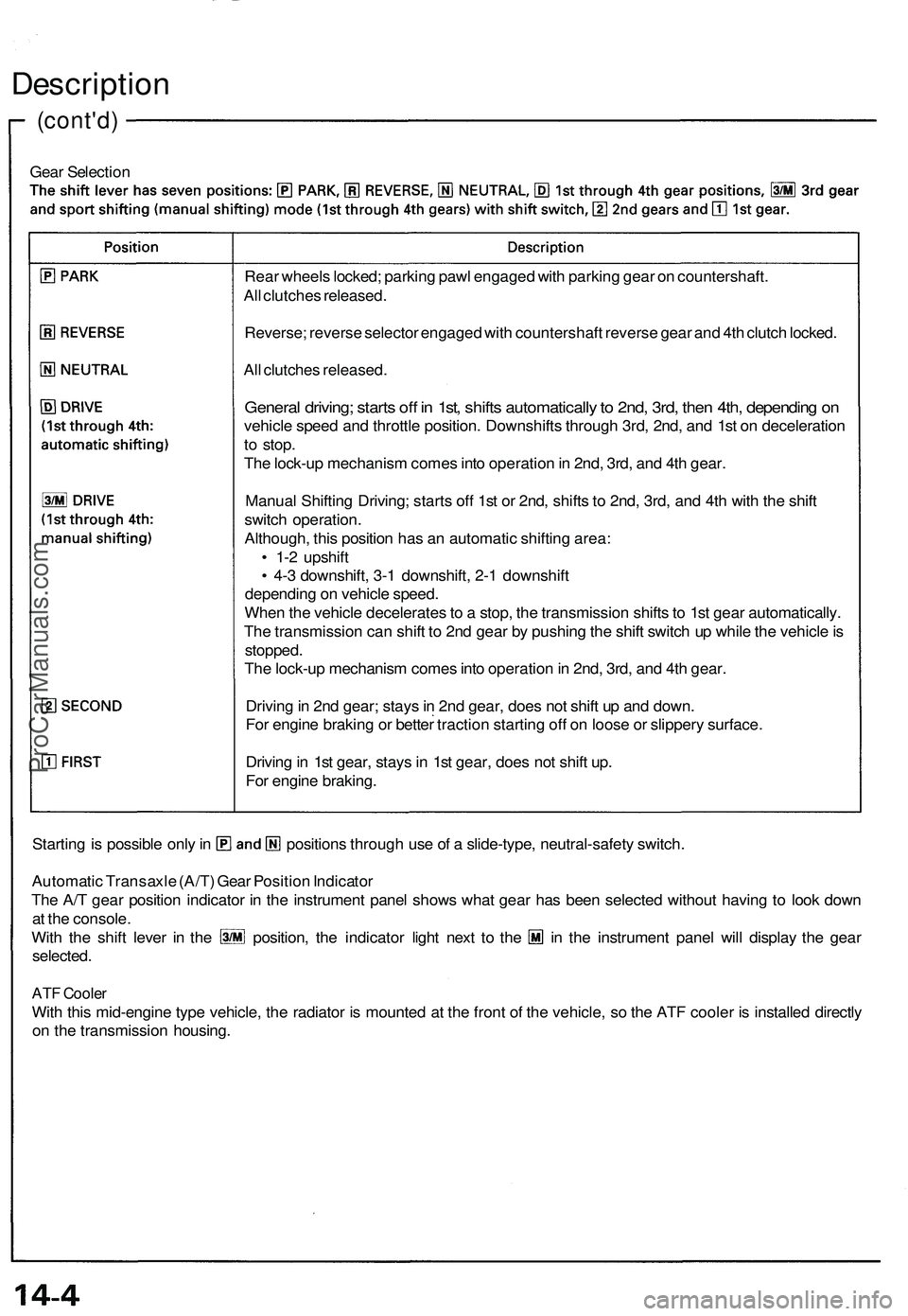
Gear Selection
Starting is possible only in positions through use of a slide-type, neutral-safety switch.
Automatic Transaxle (A/T) Gear Position Indicator
The A/T gear position indicator in the instrument panel shows what gear has been selected without having to look down
at the console.
With the shift lever in the position, the indicator light next to the in the instrument panel will display the gear
selected.
ATF Cooler
With this mid-engine type vehicle, the radiator is mounted at the front of the vehicle, so the ATF cooler is installed directly
on the transmission housing.
Rear wheels locked; parking pawl engaged with parking gear on countershaft.
All clutches released.
Reverse; reverse selector engaged with countershaft reverse gear and 4th clutch locked.
All clutches released.
General driving; starts off in 1st, shifts automatically to 2nd, 3rd, then 4th, depending on
vehicle speed and throttle position. Downshifts through 3rd, 2nd, and 1st on deceleration
to stop.
The lock-up mechanism comes into operation in 2nd, 3rd, and 4th gear.
Manual Shifting Driving; starts off 1st or 2nd, shifts to 2nd, 3rd, and 4th with the shift
switch operation.
Although, this position has an automatic shifting area:
• 1-2 upshift
• 4-3 downshift, 3-1 downshift, 2-1 downshift
depending on vehicle speed.
When the vehicle decelerates to a stop, the transmission shifts to 1st gear automatically.
The transmission can shift to 2nd gear by pushing the shift switch up while the vehicle is
stopped.
The lock-up mechanism comes into operation in 2nd, 3rd, and 4th gear.
Driving in 2nd gear; stays in 2nd gear, does not shift up and down.
For engine braking or better traction starting off on loose or slippery surface.
Driving in 1st gear, stays in 1st gear, does not shift up.
For engine braking.ProCarManuals.com
Page 716 of 1503
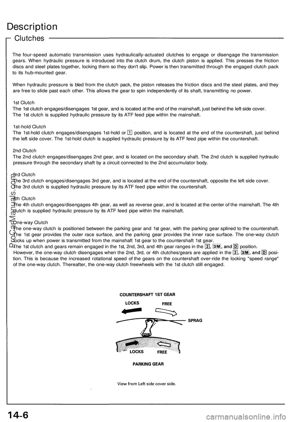
Clutches
Description
The four-speed automatic transmission uses hydraulically-actuated clutches to engage or disengage the transmission
gears. When hydraulic pressure is introduced into the clutch drum, the clutch piston is applied. This presses the friction
discs and steel plates together, locking them so they don't slip. Power is then transmitted through the engaged clutch pack
to its hub-mounted gear.
When hydraulic pressure is bled from the clutch pack, the piston releases the friction discs and the steel plates, and they
are free to slide past each other. This allows the gear to spin independently of its shaft, transmitting no power.
1st Clutch
The 1st clutch engages/disengages 1st gear, and is located at the end of the mainshaft, just behind the left side cover.
The 1st clutch is supplied hydraulic pressure by its ATF feed pipe within the mainshaft.
1st-hold Clutch
The 1st-hold clutch engages/disengages 1st-hold or position, and is located at the end of the countershaft, just behind
the left side cover. The 1st-hold clutch is supplied hydraulic pressure by its ATF feed pipe within the countershaft.
2nd Clutch
The 2nd clutch engages/disengages 2nd gear, and is located on the secondary shaft. The 2nd clutch is supplied hydraulic
pressure through the secondary shaft by a circuit connected to the 2nd accumulator body.
3rd Clutch
The 3rd clutch engages/disengages 3rd gear, and is located at the end of the countershaft, opposite the left side cover.
The 3rd clutch is supplied hydraulic pressure by its ATF feed pipe within the countershaft.
4th Clutch
The 4th clutch engages/disengages 4th gear, as well as reverse gear, and is located at the center of the mainshaft. The 4th
clutch is supplied hydraulic pressure by its ATF feed pipe within the mainshaft.
One-way Clutch
The one-way clutch is positioned between the parking gear and 1st gear, with the parking gear splined to the countershaft.
The 1st gear provides the outer race surface, and the parking gear provides the inner race surface. The one-way clutch
locks up when power is transmitted from the mainshaft 1st gear to the countershaft 1st gear.
The 1st clutch and gears remain engaged in the 1st, 2nd, 3rd, and 4th gear ranges in the position.
However, the one-way clutch disengages when the 2nd, 3rd, or 4th clutches/gears are applied in the posi-
tion. This is because the increased rotational speed of the gears on the countershaft over-ride the locking "speed range"
of the one-way clutch. Thereafter, the one-way clutch freewheels with the 1st clutch still engaged.ProCarManuals.com
Page 726 of 1503
Electronic Control System (cont'd)
Description
• Automatic shifting control in Sport Shifting mode
This position also has automatic shifting areas:
• 1-2 upshift
• 4-3 downshift, 3-1 downshift, 2-1 downshift
depending on vehicle speed. To prevent engine over-revving, the transmission has a 1-2 automatic upshift speed, and 4-3,
3-1, 2-1 downshift allowable speeds.
• When the vehicle reaches the 1-2 automatic upshift speed, the TCM outputs the 1-2 upshift signal to the transmis-
sion and the transmission upshifts to 2nd from 1st gear.
• When the vehicle is coasting over the 4-3 downshift allowable speed and 3-2 downshift allowable speed, the TCM
does not input the downshift signal from the shift switch, and the transmission does not downshift.
• When the vehicle is coasting over the 2-1 downshift allowable speed in 2nd gear, the TCM inputs the signal to wait
until it reaches the 2-1 downshift allowable speed, then the shift indicator blinks to indicate it is waiting to downshift
to
1st.
When the vehicle decelerates to a stop, the transmission shifts to 1st gear automatically.
The transmission can be shifted to 2nd gear by pushing the shift switch up while the vehicle is stopped. This allows the
vehicle to start off in 2nd gear.
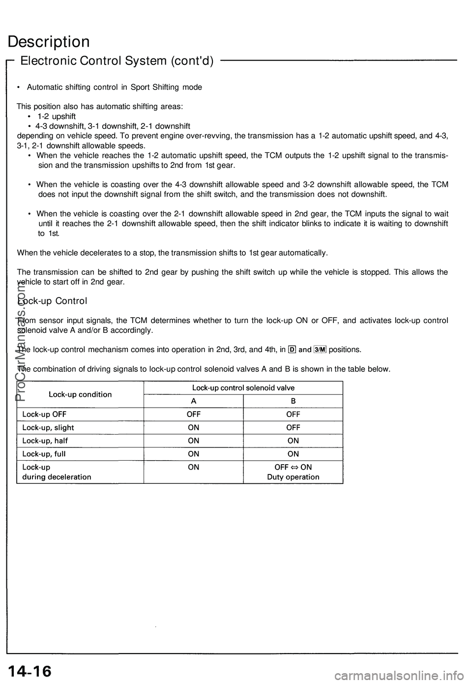
Lock-up Control
From sensor input signals, the TCM determines whether to turn the lock-up ON or OFF, and activates lock-up control
solenoid valve A and/or B accordingly.
The lock-up control mechanism comes into operation in 2nd, 3rd, and 4th, in positions.
The combination of driving signals to lock-up control solenoid valves A and B is shown in the table below.ProCarManuals.com
Page 994 of 1503
Tests
Brake Booster
Functional Test
1. With the engine stopped, depress the brake pedal
several times to deplete the vacuum reservoir, then
depress the pedal hard and hold it for 15 seconds. If
the pedal sinks, either the master cylinder is
bypassing internally, or the brake system (master
cylinder, lines, modulator, proportioning valve, or
calipers) is leaking.
2. Start the engine with the pedal depressed. If the
pedal sinks slightly, the vacuum booster is operat-
ing normally, if the pedal height does not vary, the
booster or check valve is faulty.
3. With the engine running, depress the brake pedal
lightly. Apply just enough pressure to hold back
automatic transmission creep. If the brake pedal
sinks more than 10 mm (3/8 in.) in three minutes,
the master cylinder is faulty. A slight change in
pedal height when the A/C compressor cycles on
and off if normal. (The A/C compressor load
changes the vacuum available to the booster.)
Leak Test
1. Depress the brake pedal with the engine running,
then stop the engine. If the pedal height does not
vary while depressed for 30 seconds, the vacuum
booster is OK. If the pedal rises, the booster is
faulty.
2. With the engine stopped, depress the brake pedal
several times using normal pressure. When the
pedal is first depressed, it should be low. On con-
secutive applications, the pedal height should grad-
ually rise. If the pedal position does not vary, check
the booster check valve.
Booster Check Valve Test
1. Disconnect the brake booster vacuum hose at the
booster or at the booster side of the valve.
2. Start the engine and let it idle. There should be vac-
uum. If no vacuum is available, the check valve is
not working properly. Replace the check valve and
retest.ProCarManuals.com