Page 351 of 1202
R05909
AB0118
R13006AB0119
W02045H00025
Airbag Sensor
Assembly
P Squib
D SquibSpiral
Cable
ACCON
or
DLC1
E
1TcCode 54
DI-176
- DIAGNOSTICSSUPPLEMENTAL RESTRAINT SYSTEM
1996 TERCEL (RM440U)
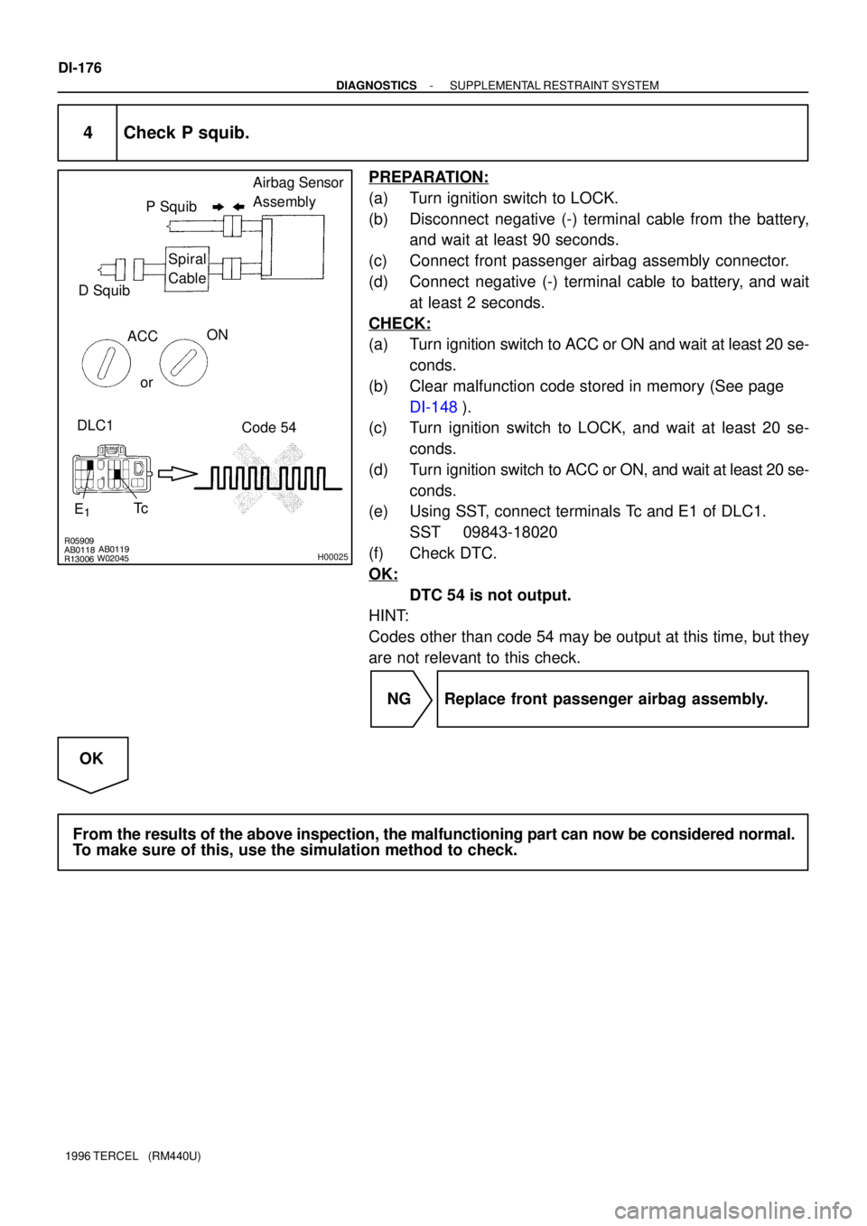
4 Check P squib.
PREPARATION:
(a) Turn ignition switch to LOCK.
(b) Disconnect negative (-) terminal cable from the battery,
and wait at least 90 seconds.
(c) Connect front passenger airbag assembly connector.
(d) Connect negative (-) terminal cable to battery, and wait
at least 2 seconds.
CHECK:
(a) Turn ignition switch to ACC or ON and wait at least 20 se-
conds.
(b) Clear malfunction code stored in memory (See page
DI-148).
(c) Turn ignition switch to LOCK, and wait at least 20 se-
conds.
(d) Turn ignition switch to ACC or ON, and wait at least 20 se-
conds.
(e) Using SST, connect terminals Tc and E1 of DLC1.
SST 09843-18020
(f) Check DTC.
OK:
DTC 54 is not output.
HINT:
Codes other than code 54 may be output at this time, but they
are not relevant to this check.
NG Replace front passenger airbag assembly.
OK
From the results of the above inspection, the malfunctioning part can now be considered normal.
To make sure of this, use the simulation method to check.
Page 353 of 1202
R05894 AB0117
H00001
Airbag Sensor
Assembly LOCK
Spiral
Cable D SquibP Squib
R14285 AB0119H00021
ON
Airbag Sensor Assembly
ACC
IG2
(+) (-)
DI-178
- DIAGNOSTICSSUPPLEMENTAL RESTRAINT SYSTEM
1996 TERCEL (RM440U)
INSPECTION PROCEDURE
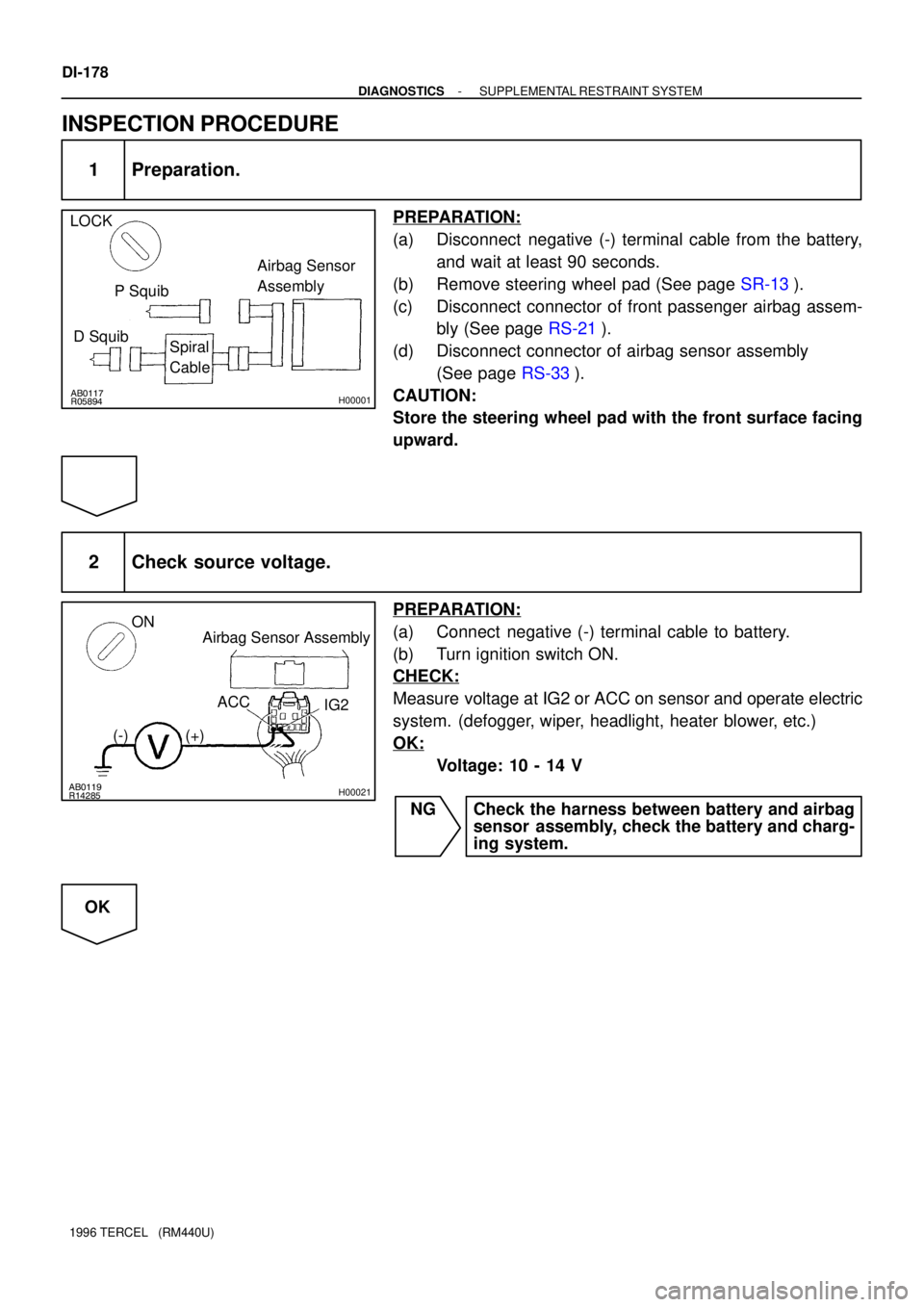
1 Preparation.
PREPARATION:
(a) Disconnect negative (-) terminal cable from the battery,
and wait at least 90 seconds.
(b) Remove steering wheel pad (See page SR-13).
(c) Disconnect connector of front passenger airbag assem-
bly (See page RS-21).
(d) Disconnect connector of airbag sensor assembly
(See page RS-33).
CAUTION:
Store the steering wheel pad with the front surface facing
upward.
2 Check source voltage.
PREPARATION:
(a) Connect negative (-) terminal cable to battery.
(b) Turn ignition switch ON.
CHECK:
Measure voltage at IG2 or ACC on sensor and operate electric
system. (defogger, wiper, headlight, heater blower, etc.)
OK:
Voltage: 10 - 14 V
NG Check the harness between battery and airbag
sensor assembly, check the battery and charg-
ing system.
OK
Page 354 of 1202
H00003
ON
- DIAGNOSTICSSUPPLEMENTAL RESTRAINT SYSTEM
DI-179
1996 TERCEL (RM440U)
3 Does SRS warning light turn off?
PREPARATION:
(a) Turn ignition switch to LOCK.
(b) Connect steering wheel pad connector.
(c) Connect front passenger airbag assembly connector.
(d) Connect airbag sensor assembly connector.
(e) Turn ignition switch ON.
CHECK:
Operate electric system checked in defogger, wiper, headlight,
heater blower, etc. and check that SRS warning light goes off.
NO Check for DTCs. If a DTC is output, perform trou-
bleshooting for the DTC. If a normal code is out-
put, replace airbag sensor assembly.
YES
From the results of the above inspection, the malfunctioning part can now be considered normal.
To make sure of this, use the simulation method to check.
Page 355 of 1202
R15076
F6
B
EA2 B-R
MAIN
FL
Battery ALT13 Driver Side J/B
SRS
1J
F7 12
B-R1
1E
4 8 5
Tc LA B-Y R-G
*1
12 1F
1F
1F
1F 1KSRS Warning Light
45
B-Y
*2
AB DLC1
11 P-B
P-B P-BEA1Tc
(w/ Front Passenger Airbag)
*1: LA - 8
*2: Tc - 7
(w/o Front Passenger Airbag)
*1: LA - 6
*2: Tc - 5Airbag Sensor
Assembly
IG1
B-Y
B-Y4
7
5 DI-180
- DIAGNOSTICSSUPPLEMENTAL RESTRAINT SYSTEM
1996 TERCEL (RM440U)
SRS Warning Light System Malfunction (Always lit up when igni-
tion switch is in LOCK position.)
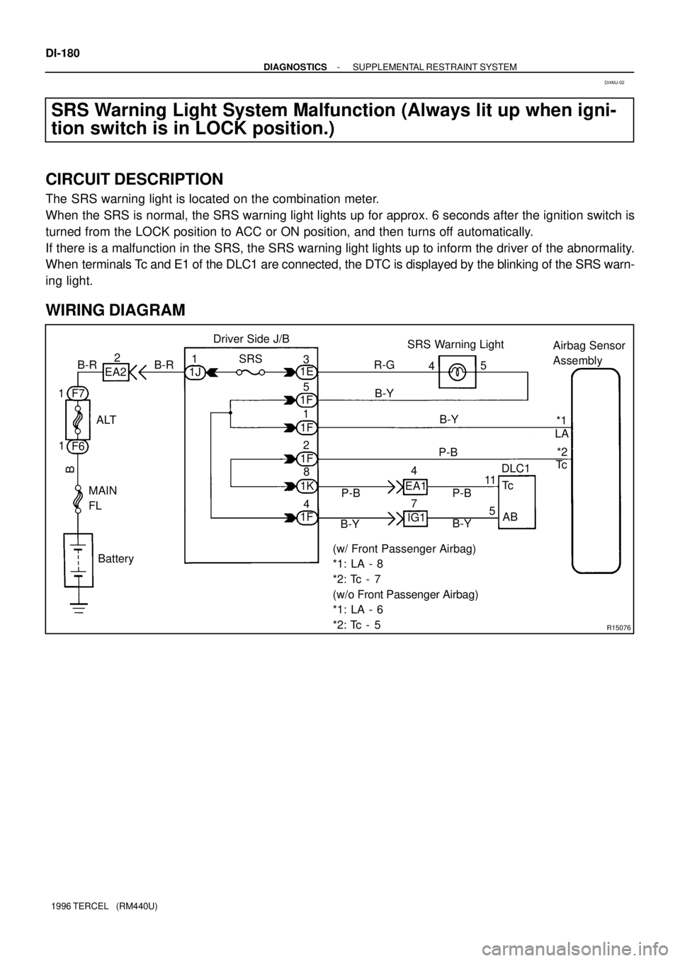
CIRCUIT DESCRIPTION
The SRS warning light is located on the combination meter.
When the SRS is normal, the SRS warning light lights up for approx. 6 seconds after the ignition switch is
turned from the LOCK position to ACC or ON position, and then turns off automatically.
If there is a malfunction in the SRS, the SRS warning light lights up to inform the driver of the abnormality.
When terminals Tc and E1 of the DLC1 are connected, the DTC is displayed by the blinking of the SRS warn-
ing light.
WIRING DIAGRAM
DI4MJ-02
Page 357 of 1202
N14677
Fuse
DI-182
- DIAGNOSTICSSUPPLEMENTAL RESTRAINT SYSTEM
1996 TERCEL (RM440U)
SRS Warning Light System Malfunction (Does not light up when
ignition switch is turned to ACC or ON.)
CIRCUIT DESCRIPTION
The SRS warning light is located on the combination meter.
When the SRS is normal, the SRS warning light lights up for approx. 6 seconds after the ignition switch is
turned from LOCK position to ACC or ON position, and then turns off automatically.
If there is a malfunction in the SRS, the SRS warning light lights up to inform the driver of the abnormality
When terminals Tc and E1 of the DLC1 are connected, the DTC is displayed by the blinking of the SRS warn-
ing light.
WIRING DIAGRAM
Refer to page DI-180 for the WIRING DIAGRAM.
INSPECTION PROCEDURE
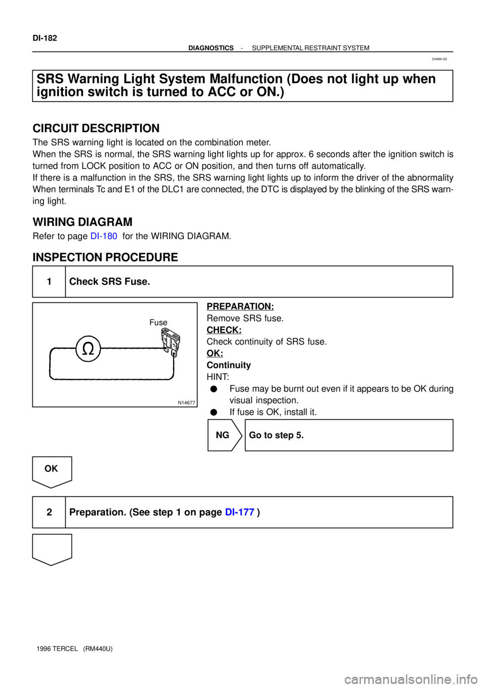
1 Check SRS Fuse.
PREPARATION:
Remove SRS fuse.
CHECK:
Check continuity of SRS fuse.
OK:
Continuity
HINT:
�Fuse may be burnt out even if it appears to be OK during
visual inspection.
�If fuse is OK, install it.
NG Go to step 5.
OK
2 Preparation. (See step 1 on page DI-177)
DI4MK-02
Page 361 of 1202
AB0117 AB0118 AB0119H00270
LOCKACCON
or
AB0118
R14305AB0119
H00030
ACCON
or
E1
Tc
(+) (-)DLC1
DI-186
- DIAGNOSTICSSUPPLEMENTAL RESTRAINT SYSTEM
1996 TERCEL (RM440U)
INSPECTION PROCEDURE
HINT:
If the DTC is not displayed, do the following troubleshooting.
1 Does SRS warning light up for approx. 6 seconds?
CHECK:
Check operation of SRS warning light after ignition switch is
turned from LOCK position to ACC or ON position.
NO Check SRS warning light system.
(See page DI-180, DI-182)
YES
2 Check voltage between terminals Tc and E1 of DLC1.
PREPARATION:
Turn ignition switch to ACC or ON.
CHECK:
Measure voltage between terminals Tc and E1 of DLC1.
OK:
Voltage: 10 - 14 V
OK Go to step 4.
NG
Page 363 of 1202
AB0117 AB0118 AB0119
R12658H00032
LOCK
ACC
ON
or
Airbag Sensor Assembly
Tc
DI-188
- DIAGNOSTICSSUPPLEMENTAL RESTRAINT SYSTEM
1996 TERCEL (RM440U)
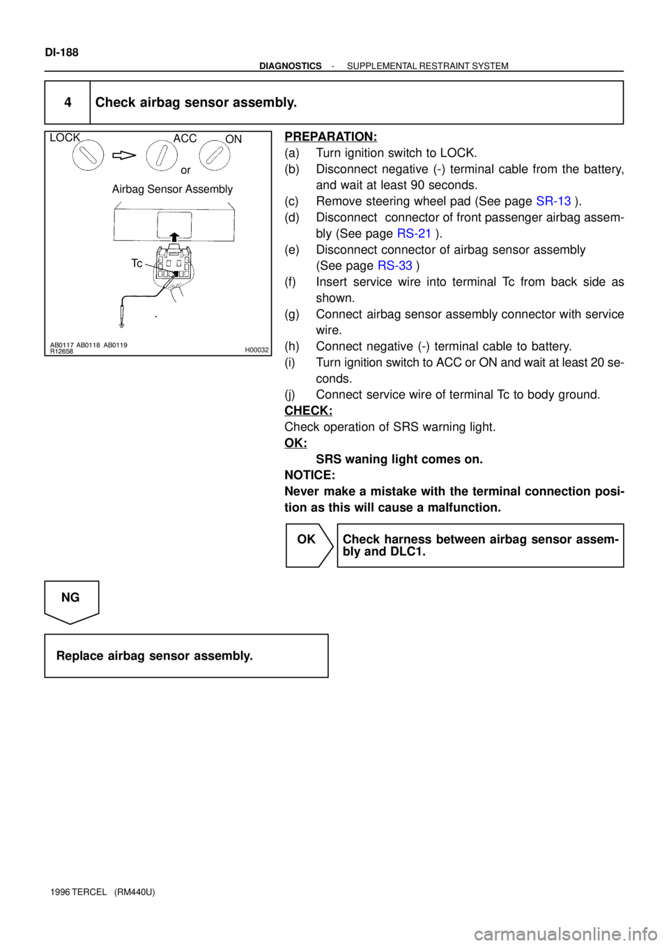
4 Check airbag sensor assembly.
PREPARATION:
(a) Turn ignition switch to LOCK.
(b) Disconnect negative (-) terminal cable from the battery,
and wait at least 90 seconds.
(c) Remove steering wheel pad (See page SR-13).
(d) Disconnect connector of front passenger airbag assem-
bly (See page RS-21).
(e) Disconnect connector of airbag sensor assembly
(See page RS-33)
(f) Insert service wire into terminal Tc from back side as
shown.
(g) Connect airbag sensor assembly connector with service
wire.
(h) Connect negative (-) terminal cable to battery.
(i) Turn ignition switch to ACC or ON and wait at least 20 se-
conds.
(j) Connect service wire of terminal Tc to body ground.
CHECK:
Check operation of SRS warning light.
OK:
SRS waning light comes on.
NOTICE:
Never make a mistake with the terminal connection posi-
tion as this will cause a malfunction.
OK Check harness between airbag sensor assem-
bly and DLC1.
NG
Replace airbag sensor assembly.
Page 364 of 1202
AB0117
R14303
H00033
Airbag Sensor Assembly
Tc
LOCK
- DIAGNOSTICSSUPPLEMENTAL RESTRAINT SYSTEM
DI-189
1996 TERCEL (RM440U)
If the DTC is displayed without a DTC check procedure, do the following trou-
bleshooting.
1 Check resistance between terminal Tc of airbag sensor assembly and body
ground.
PREPARATION:
(a) Turn ignition switch to LOCK.
(b) Disconnect negative (-) terminal cable from the battery,
and wait at least 90 seconds.
(c) Disconnect airbag sensor assembly connector.
CHECK:
Check resistance between terminal Tc of airbag sensor assem-
bly connector and body ground.
OK:
Resistance: 1MW or higher
NG Repair or replace harness or connector.
OK
Replace airbag sensor assembly.


