Page 471 of 1202
P20948
P20953
Timing Mark
Installation
Mark
P20746
P20748
P20749
- ENGINE MECHANICALCYLINDER HEAD
EM-49
1996 TERCEL (RM440U)
8. SET NO.1 CYLINDER TO TDC/COMPRESSION
(a) Turn the crankshaft pulley, and align its groove with timing
mark º0º of the No.1 timing belt cover.
(b) Turn the camshaft, and align the hole of the camshaft tim-
ing pulley on the side with the 5E mark with the timing
mark of the bearing cap.
9. INSTALL TIMING BELT
(a) Starting from the right hand side of the pulley and instal-
ling the belt counterclockwise.
(b) Loosen the No.1 idler pulley mounting bolt until the pulley
is moved slightly by the spring tension.
(c) Turn the crankshaft pulley 2 revolutions from TDC to TDC.
NOTICE:
Always turn the crankshaft clockwise.
Page 472 of 1202

P20538
Timing Mark
Installation Mark
P20361
P20286
Seal Packing
P20406
EM-50
- ENGINE MECHANICALCYLINDER HEAD
1996 TERCEL (RM440U)
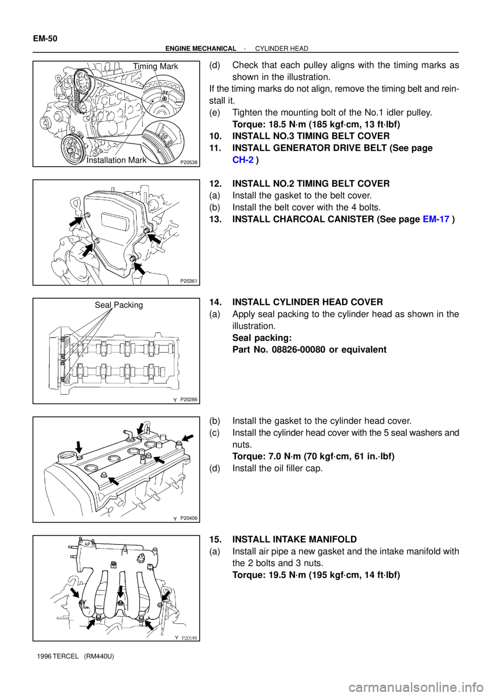
(d) Check that each pulley aligns with the timing marks as
shown in the illustration.
If the timing marks do not align, remove the timing belt and rein-
stall it.
(e) Tighten the mounting bolt of the No.1 idler pulley.
Torque: 18.5 N´m (185 kgf´cm, 13 ft´lbf)
10. INSTALL NO.3 TIMING BELT COVER
11. INSTALL GENERATOR DRIVE BELT (See page
CH-2)
12. INSTALL NO.2 TIMING BELT COVER
(a) Install the gasket to the belt cover.
(b) Install the belt cover with the 4 bolts.
13. INSTALL CHARCOAL CANISTER (See page EM-17)
14. INSTALL CYLINDER HEAD COVER
(a) Apply seal packing to the cylinder head as shown in the
illustration.
Seal packing:
Part No. 08826-00080 or equivalent
(b) Install the gasket to the cylinder head cover.
(c) Install the cylinder head cover with the 5 seal washers and
nuts.
Torque: 7.0 N´m (70 kgf´cm, 61 in.´lbf)
(d) Install the oil filler cap.
15. INSTALL INTAKE MANIFOLD
(a) Install air pipe a new gasket and the intake manifold with
the 2 bolts and 3 nuts.
Torque: 19.5 N´m (195 kgf´cm, 14 ft´lbf)
Page 492 of 1202
EM0JQ-06
EM9411
EM9412
P20480
SST
P20478
SST
P20477
12 mm
Hexagon
Wrench EM-70
- ENGINE MECHANICALCYLINDER BLOCK
1996 TERCEL (RM440U)
DISASSEMBLY
1. M/T:
REMOVE CLUTCH COVER AND DISC
2. REMOVE FLYWHEEL (M/T) OR DRIVE PLATE (A/T)
3. REMOVE REAR END PLATE
4. INSTALL ENGINE TO ENGINE STAND FOR DIS-
ASSEMBLY
5. REMOVE TIMING BELT AND PULLEYS
6. REMOVE CYLINDER HEAD
7. REMOVE OIL DIPSTICK GUIDE AND GENERATOR
ADJUSTING BAR
8. REMOVE WATER PUMP WITH WATER INLET PIPE
9. REMOVE GENERATOR BRACKET
10. REMOVE KNOCK SENSOR
Using SST, remove the knock sensor.
SST 09816-30010
11. REMOVE RH ENGINE MOUNTING BRACKET
12. REMOVE OIL FILTER
13. REMOVE OIL PRESSURE SWITCH
Using SST, remove the oil pressure switch.
SST 09816-30010
14. REMOVE OIL PUMP AND PRESSURE REGULATOR
VA LV E
15. REMOVE OIL FILTER UNION
Using a 12 mm hexagon wrench, remove the oil filter union.
Page 512 of 1202
P20750
P20480
SST
P20545
EM9412
EM7333
EM-90
- ENGINE MECHANICALCYLINDER BLOCK
1996 TERCEL (RM440U)
15. INSTALL RH ENGINE MOUNTING BRACKET
Torque: 58 N´m (590 kgf´cm, 43 ft´lbf)
16. INSTALL KNOCK SENSOR
Using SST, install the knock sensor.
SST 09816-30010
Torque: 45 N´m (450 kgf´cm, 33 ft´lbf)
17. INSTALL GENERATOR BRACKET
Torque: 24 N´m (240 kgf´cm, 18 ft´lbf)
18. INSTALL WATER PUMP WITH WATER INLET PIPE
19. INSTALL OIL DIPSTICK GUIDE AND GENERATOR AD-
JUSTING BAR
20. INSTALL CYLINDER HEAD
21. INSTALL TIMING BELT AND PULLEYS
22. REMOVE ENGINE STAND
23. INSTALL REAR END PLATE
Torque: 10 N´m (100 kgf´cm, 7 ft´lbf)
24. M/T:
INSTALL FLYWHEEL
(a) Apply adhesive to 2 or 3 threads of new mounting bolt
end.
Adhesive:
Part No. 08833-00070, THREE BOND 1324 or
equivalent
Page 623 of 1202
LU08D-05
P20907
EM9278
EM9755
P20160
- LUBRICATIONOIL PUMP
LU-7
1996 TERCEL (RM440U)
REMOVAL
HINT:
When repairing the oil pump, the oil pan and strainer should be
removed and cleaned.
1. REMOVE HOOD
2. REMOVE OIL DIPSTICK
3. DRAIN ENGINE OIL
4. REMOVE TIMING BELT (See page EM-12)
5. SUSPEND ENGINE WITH ENGINE SLING DEVICE
6. REMOVE CRANKSHAFT TIMING PULLEY(See page
EM-12)
7. w/ A/C:
REMOVE A/C COMPRESSOR AND MOUNTING
BRACKET
(a) Disconnect the compressor connector.
(b) Remove the 4 compressor mounting bolts.
HINT:
Put a side compressor, and suspend it.
(c) Remove the 4 bolts and compressor mounting
bracket.
8. DISCONNECT FRONT EXHAUST PIPE
(a) Remove the 2 bolts and the 2 compresson springs.
(b) Disconnect the exhaust pipe.
Page 632 of 1202
LU-16
- LUBRICATIONOIL PUMP
1996 TERCEL (RM440U)
(a) Place a new gasket on the exhaust pipe.
(b) Connect the exhaust pipe to the exhaust manifold with 2
compresson springs and 2 bolts.
Torque: 62 N´m (630 kgf´cm, 46 ft´lbf)
6. w/ A/C:
INSTALL A/C COMPRESSOR AND MOUNTING
BRACKET
(a) Install the compressor mounting bracket with the 4 bolts.
Torque: 27 N´m (270 kgf´cm, 20 ft´lbf)
(b) Install the A/C compressor to the bracket with the 4 bolts.
Torque: 25 N´m (250 kgf´cm, 18 ft´lbf)
(c) Connect the A/C compressor connector.
7. INSTALL CRANKSHAFT TIMING PULLEY (See page
EM-17)
8. INSTALL TIMING BELT (See page EM-17)
9. INSTALL OIL DIPSTICK
10. FILL WITH ENGINE OIL
11. START ENGINE AND CHECK FOR LEAKS
12. CHECK ENGINE OIL LEVEL
13. INSTALL HOOD
Page 645 of 1202
IG08M-04
P21254
Connector Clamp
P21034
- IGNITIONCRANKSHAFT POSITION SENSOR
IG-13
1996 TERCEL (RM440U)
REMOVAL
1. DISCONNECT CRANKSHAFT POSITION SENSOR
CONNECTOR AND CLAMP
2. REMOVE RH ENGINE UNDER COVER
3. REMOVE NO.2 TIMING BELT COVER (See page
EM-12)
4. REMOVE CRANKSHAFT POSITION SENSOR
Remove the bolt and disconnect the crankshaft position sensor.
Torque: 8 N´m (80 kgf´cm, 69 in.´lbf)