Page 431 of 1202
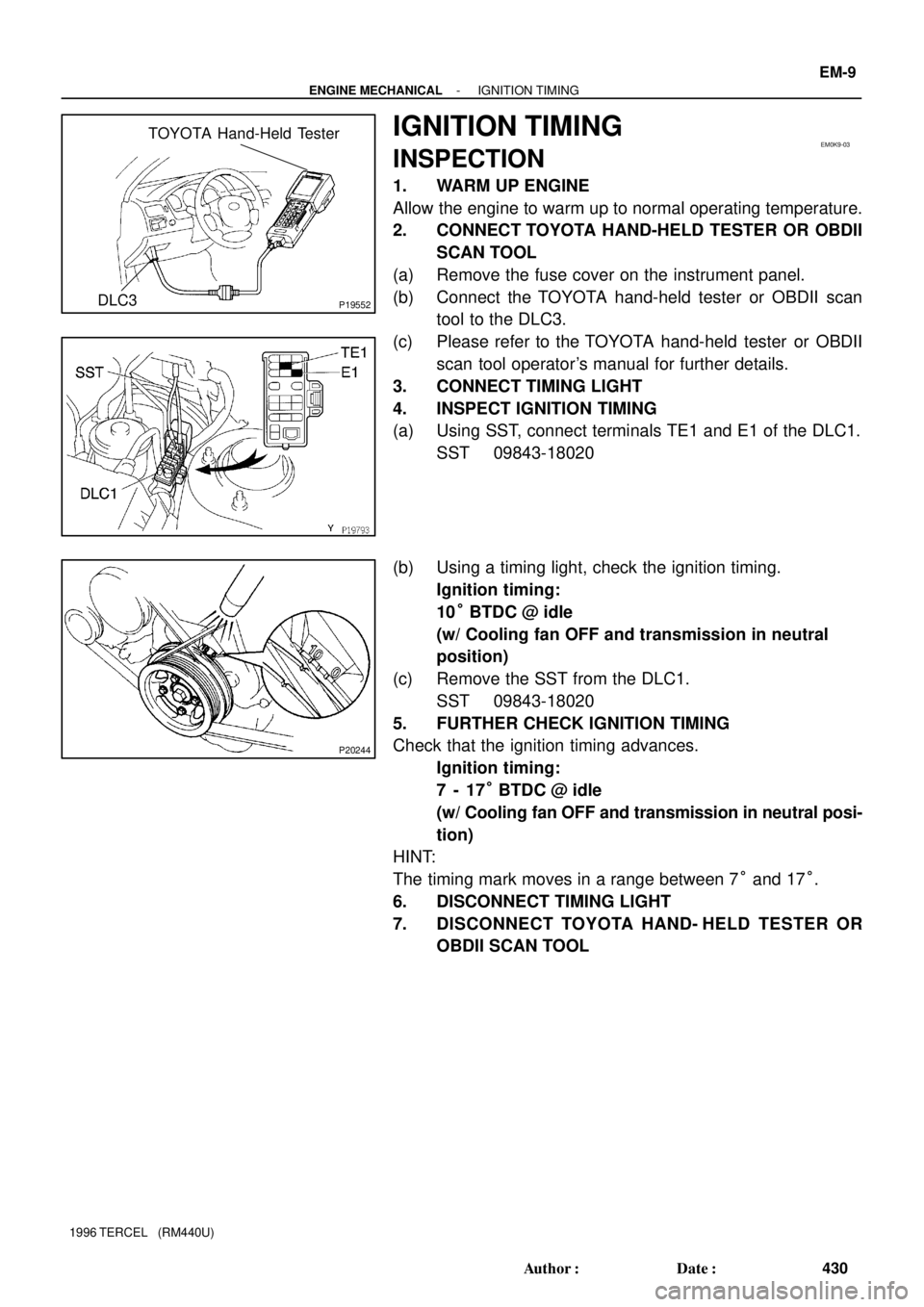
P19552
TOYOTA Hand-Held Tester
DLC3EM0K9-03
P20244
- ENGINE MECHANICALIGNITION TIMING
EM-9
430 Author�: Date�:
1996 TERCEL (RM440U)
IGNITION TIMING
INSPECTION
1. WARM UP ENGINE
Allow the engine to warm up to normal operating temperature.
2. CONNECT TOYOTA HAND-HELD TESTER OR OBDII
SCAN TOOL
(a) Remove the fuse cover on the instrument panel.
(b) Connect the TOYOTA hand-held tester or OBDII scan
tool to the DLC3.
(c) Please refer to the TOYOTA hand-held tester or OBDII
scan tool operator's manual for further details.
3. CONNECT TIMING LIGHT
4. INSPECT IGNITION TIMING
(a) Using SST, connect terminals TE1 and E1 of the DLC1.
SST 09843-18020
(b) Using a timing light, check the ignition timing.
Ignition timing:
10° BTDC @ idle
(w/ Cooling fan OFF and transmission in neutral
position)
(c) Remove the SST from the DLC1.
SST 09843-18020
5. FURTHER CHECK IGNITION TIMING
Check that the ignition timing advances.
Ignition timing:
7 - 17° BTDC @ idle
(w/ Cooling fan OFF and transmission in neutral posi-
tion)
HINT:
The timing mark moves in a range between 7° and 17°.
6. DISCONNECT TIMING LIGHT
7. DISCONNECT TOYOTA HAND- HELD TESTER OR
OBDII SCAN TOOL
Page 432 of 1202
EM18V-02
EM-10
- ENGINE MECHANICALIDLE SPEED
431 Author�: Date�:
1996 TERCEL (RM440U)
IDLE SPEED
INSPECTION
1. INITIAL CONDITIONS
(a) Engine coolant at normal operating temperature.
(b) Air cleaner installed.
(c) All pipes and hoses of air induction system connected.
(d) All accessories switched OFF.
(e) All vacuum lines properly connected.
HINT:
All vacuum hoses for EGR system, etc. should be properly connected.
(f) SFI system wiring connectors fully plugged.
(g) Ignition timing set correctly.
(h) Transmission in neutral position.
2. CONNECT TOYOTA HAND-HELD TESTER OR OBDII SCAN TOOL (See page EM-9)
3. INSPECT IDLE SPEED
(a) Race the engine speed at 2,500 rpm for approx. 90 seconds.
(b) Check the idle speed.
Idle speed:
750 ± 50 rpm
(w/ Cooling fan OFF and transmission in neutral position)
If the idle speed is not as specified, check the IAC valve and air intake system.
4. DISCONNECT TOYOTA HAND-HELD TESTER OR OBDII SCAN TOOL
Page 447 of 1202
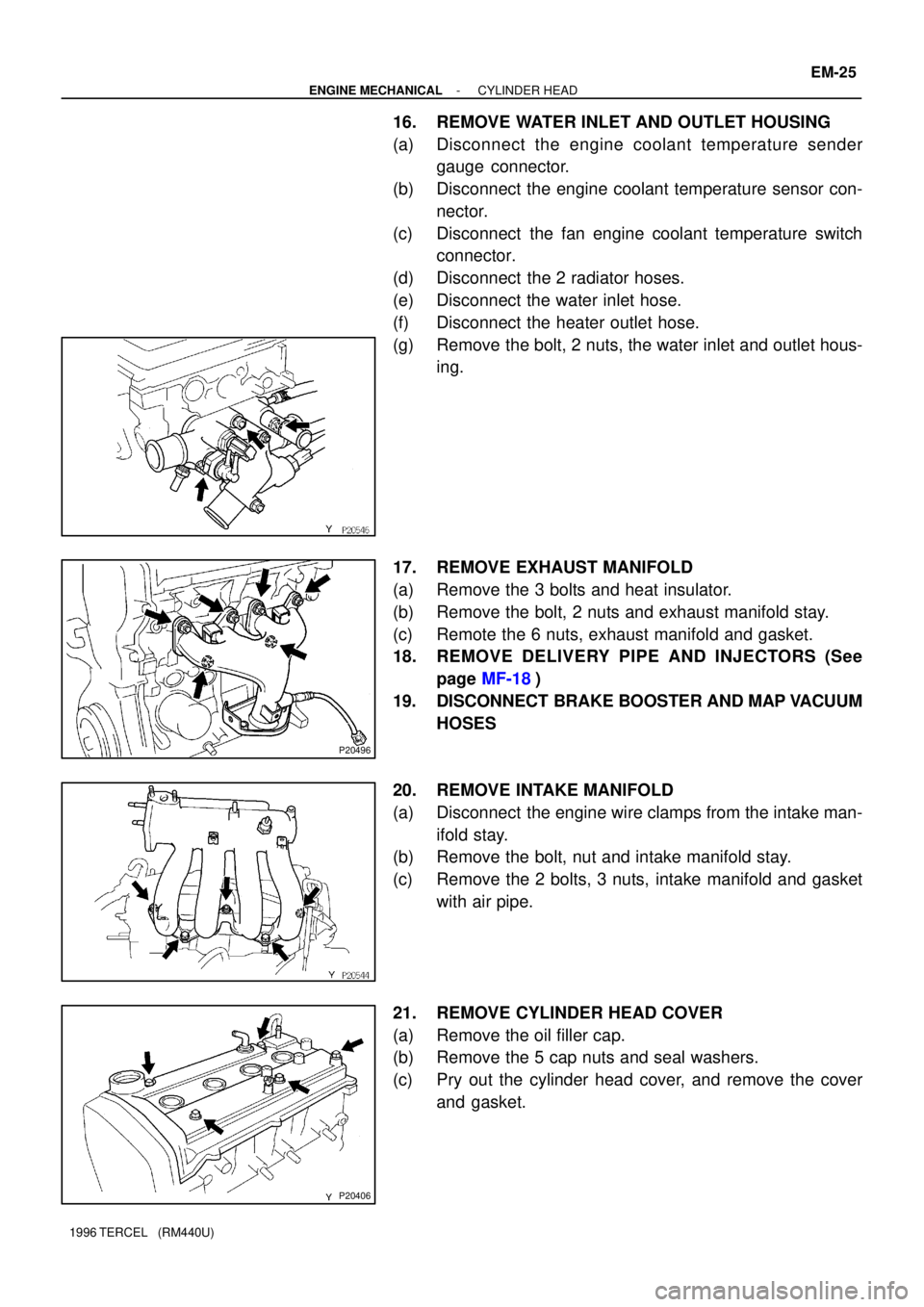
P20496
P20406
- ENGINE MECHANICALCYLINDER HEAD
EM-25
1996 TERCEL (RM440U)
16. REMOVE WATER INLET AND OUTLET HOUSING
(a) Disconnect the engine coolant temperature sender
gauge connector.
(b) Disconnect the engine coolant temperature sensor con-
nector.
(c) Disconnect the fan engine coolant temperature switch
connector.
(d) Disconnect the 2 radiator hoses.
(e) Disconnect the water inlet hose.
(f) Disconnect the heater outlet hose.
(g) Remove the bolt, 2 nuts, the water inlet and outlet hous-
ing.
17. REMOVE EXHAUST MANIFOLD
(a) Remove the 3 bolts and heat insulator.
(b) Remove the bolt, 2 nuts and exhaust manifold stay.
(c) Remote the 6 nuts, exhaust manifold and gasket.
18. REMOVE DELIVERY PIPE AND INJECTORS (See
page MF-18)
19. DISCONNECT BRAKE BOOSTER AND MAP VACUUM
HOSES
20. REMOVE INTAKE MANIFOLD
(a) Disconnect the engine wire clamps from the intake man-
ifold stay.
(b) Remove the bolt, nut and intake manifold stay.
(c) Remove the 2 bolts, 3 nuts, intake manifold and gasket
with air pipe.
21. REMOVE CYLINDER HEAD COVER
(a) Remove the oil filler cap.
(b) Remove the 5 cap nuts and seal washers.
(c) Pry out the cylinder head cover, and remove the cover
and gasket.
Page 474 of 1202
EM-52
- ENGINE MECHANICALCYLINDER HEAD
1996 TERCEL (RM440U)
HINT:
Avoid applying an excess amount to the surface. Be especially
careful near oil passages.
�Parts must be assembled within 15 minutes of ap-
plication. Otherwise, the material must be removed
and reapplied.
�Immediately remove nozzle from tube and reinstall
cap.
�Do not pour in any coolant until at least 2 hours after
installation is completed.
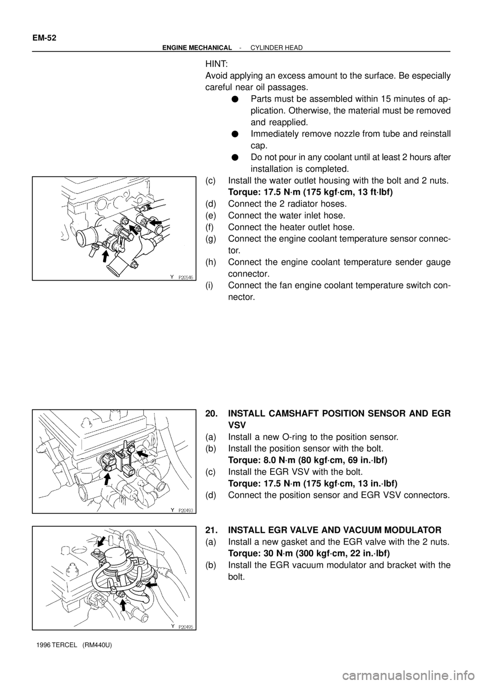
(c) Install the water outlet housing with the bolt and 2 nuts.
Torque: 17.5 N´m (175 kgf´cm, 13 ft´lbf)
(d) Connect the 2 radiator hoses.
(e) Connect the water inlet hose.
(f) Connect the heater outlet hose.
(g) Connect the engine coolant temperature sensor connec-
tor.
(h) Connect the engine coolant temperature sender gauge
connector.
(i) Connect the fan engine coolant temperature switch con-
nector.
20. INSTALL CAMSHAFT POSITION SENSOR AND EGR
VSV
(a) Install a new O-ring to the position sensor.
(b) Install the position sensor with the bolt.
Torque: 8.0 N´m (80 kgf´cm, 69 in.´lbf)
(c) Install the EGR VSV with the bolt.
Torque: 17.5 N´m (175 kgf´cm, 13 in.´lbf)
(d) Connect the position sensor and EGR VSV connectors.
21. INSTALL EGR VALVE AND VACUUM MODULATOR
(a) Install a new gasket and the EGR valve with the 2 nuts.
Torque: 30 N´m (300 kgf´cm, 22 in.´lbf)
(b) Install the EGR vacuum modulator and bracket with the
bolt.
Page 480 of 1202
P20565
M/T EM-58
- ENGINE MECHANICALENGINE UNIT
1996 TERCEL (RM440U)
�Engine coolant temperature sender gauge connec-
tor
�Engine coolant temperature sensor connector
�Camshaft position sensor connector
�EGR VSV
�Fan engine coolant temperature switch connector
�A/T only:
Lock-up solenoid connector
�A/T only:
Park/Neutral position switch connector
�M/T only:
Backup light switch connector
�A/T only:
No.2 vehicle speed sensor connector
�Ground strap
�Throttle position sensor connector
�IAC valve connector
�Injector connectors
�Crankshaft position sensor connector
�Knock sensor connector
�Starter connector and wire
�Generator connector and wire
15. M/T only:
REMOVE CLUTCH RELEASE CYLINDER WITHOUT
DISCONNECTING TUBE
(a) Remove the 3 bolts, release cylinder and tube from the
transaxle.
(b) Disconnect the ground strap.
16. M/T:
DISCONNECT CONTROL CABLE(S) FROM TRANS-
AXLE
(a) Remove the clip and plate washer.
(b) Remove the retainer from the cable.
Page 488 of 1202
EM-66
- ENGINE MECHANICALENGINE UNIT
1996 TERCEL (RM440U)
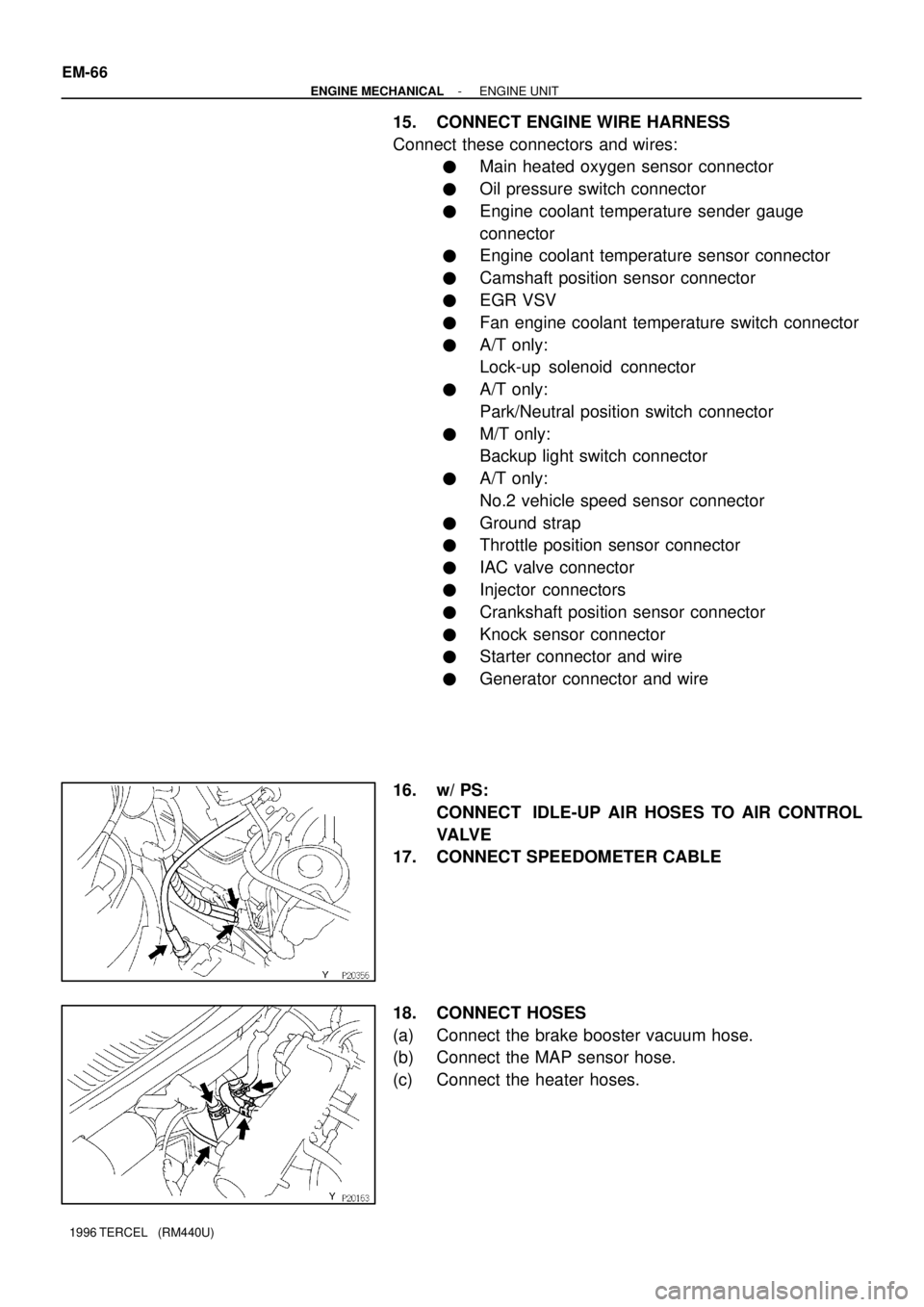
15. CONNECT ENGINE WIRE HARNESS
Connect these connectors and wires:
�Main heated oxygen sensor connector
�Oil pressure switch connector
�Engine coolant temperature sender gauge
connector
�Engine coolant temperature sensor connector
�Camshaft position sensor connector
�EGR VSV
�Fan engine coolant temperature switch connector
�A/T only:
Lock-up solenoid connector
�A/T only:
Park/Neutral position switch connector
�M/T only:
Backup light switch connector
�A/T only:
No.2 vehicle speed sensor connector
�Ground strap
�Throttle position sensor connector
�IAC valve connector
�Injector connectors
�Crankshaft position sensor connector
�Knock sensor connector
�Starter connector and wire
�Generator connector and wire
16. w/ PS:
CONNECT IDLE-UP AIR HOSES TO AIR CONTROL
VA LV E
17. CONNECT SPEEDOMETER CABLE
18. CONNECT HOSES
(a) Connect the brake booster vacuum hose.
(b) Connect the MAP sensor hose.
(c) Connect the heater hoses.
Page 522 of 1202

EC0JP-01
EC-8
- EMISSION CONTROLEXHAUST GAS RECIRCULATION (EGR) SYSTEM
1996 TERCEL (RM440U)
INSPECTION
1. INSPECT AND CLEAN FILTER IN EGR VACUUM MOD-
ULATOR
(a) Remove the cap and filter.
(b) Check the filter for contamination or damage.
(c) Using compressed air, clean the filter.
(d) Reinstall the filter and cap.
HINT:
Install the filter with the coarser surface facing the stmospheric
side (outward).
2. INSTALL VACUUM GAUGE
Using 3 - way connector, connect a vacuum gauge to the EGR
valve vacuum hose as shown in the illustration.
3. INSPECT SEATING OF EGR VALVE
Start the engine and check that the engine starts and runs at
idle.
4. INSPECT OPERATION VSV WITH COLD ENGINE
(a) The engine coolant temperature shold be below 45°C
(113°F).
(b) Check that the vacuum gauge indicates zero at 2,500
rpm.
5. INSPECT OPERATION OF VSV AND EGR VACUUM
MODULATOR WITH HOT ENGINE
(a) Warm up the engine to above 60°C (140°F).
(b) Check that the vacuum gauge indicates low vacuum at
2,500 rpm.
(c) Check that the vacuum gauge indicates zero at idle.
(d) Disconnect the vacuum hose from port R of the EGR vac-
uum modulator and connect port R directley to the intake
manifold with another hose.
(e) Check that the vacuum gauge indicates high vacuum at
2,500 rpm.
HINT:
As a large amount of exhaust gas enters, the will misfire slghtly.
6. REMOVE VACUUM GAUGE
Remove the vacuum gauge and reconnect the vacuum hoses
to the proper locations.
Page 558 of 1202
SF199-02
- MFIIDLE AIR CONTROL (IAC) VALVE
MF-33
557 Author�: Date�:
1996 TERCEL (RM440U)
IDLE AIR CONTROL (IAC) VALVE
ON-VEHICLE INSPECTION
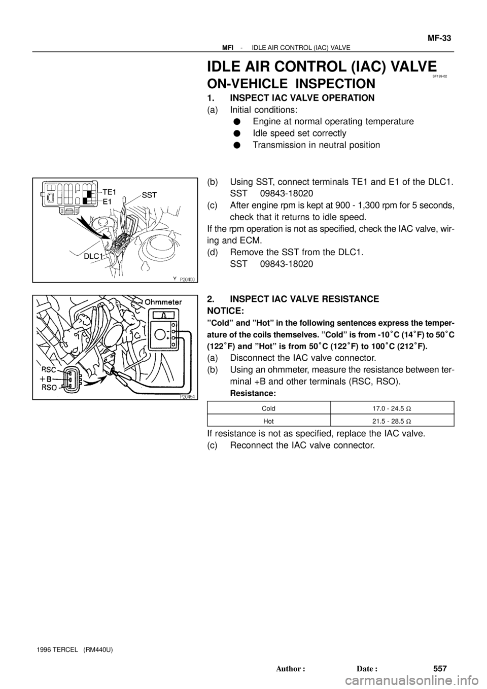
1. INSPECT IAC VALVE OPERATION
(a) Initial conditions:
�Engine at normal operating temperature
�Idle speed set correctly
�Transmission in neutral position
(b) Using SST, connect terminals TE1 and E1 of the DLC1.
SST 09843-18020
(c) After engine rpm is kept at 900 - 1,300 rpm for 5 seconds,
check that it returns to idle speed.
If the rpm operation is not as specified, check the IAC valve, wir-
ing and ECM.
(d) Remove the SST from the DLC1.
SST 09843-18020
2. INSPECT IAC VALVE RESISTANCE
NOTICE:
ºColdº and ºHotº in the following sentences express the temper-
ature of the coils themselves. ºColdº is from -10°C (14°F) to 50°C
(122°F) and ºHotº is from 50°C (122°F) to 100°C (212°F).
(a) Disconnect the IAC valve connector.
(b) Using an ohmmeter, measure the resistance between ter-
minal +B and other terminals (RSC, RSO).
Resistance:
Cold17.0 - 24.5 W
Hot21.5 - 28.5 W
If resistance is not as specified, replace the IAC valve.
(c) Reconnect the IAC valve connector.