Page 259 of 1202
S00591
From Battery
Ignition Coil
Spark Plug
IGC1
IGC2
GND TA C IGT1
IGT2
To Tachometer ECM G
NE
No.1 Cylinder
No.4 Cylinder
Various
Sensor
IGF
No.2 Cylinder
No.3 Cylinder Camshaft
Position
Sensor
Crankshaft
Position
SensorIgniter
DI-84
- DIAGNOSTICSENGINE
1996 TERCEL (RM440U)
DTC P1300 Ignition Circuit Malfunction
CIRCUIT DESCRIPTION
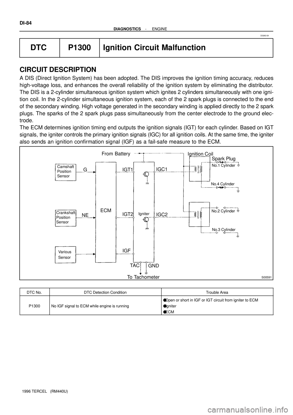
A DIS (Direct Ignition System) has been adopted. The DIS improves the ignition timing accuracy, reduces
high-voltage loss, and enhances the overall reliability of the ignition system by eliminating the distributor.
The DIS is a 2-cylinder simultaneous ignition system which ignites 2 cylinders simultaneously with one igni-
tion coil. In the 2-cylinder simultaneous ignition system, each of the 2 spark plugs is connected to the end
of the secondary winding. High voltage generated in the secondary winding is applied directly to the 2 spark
plugs. The sparks of the 2 spark plugs pass simultaneously from the center electrode to the ground elec-
trode.
The ECM determines ignition timing end outputs the ignition signals (IGT) for each cylinder. Based on IGT
signals, the igniter controls the primary ignition signals (IGC) for all ignition coils. At the same time, the igniter
also sends an ignition confirmation signal (IGF) as a fail-safe measure to the ECM.
DTC No.DTC Detection ConditionTrouble Area
P1300No IGF signal to ECM while engine is running
�Open or short in IGF or IGT circuit from igniter to ECM
�Igniter
�ECM
DI3A0-04
Page 263 of 1202
DI-88
- DIAGNOSTICSENGINE
1996 TERCEL (RM440U)
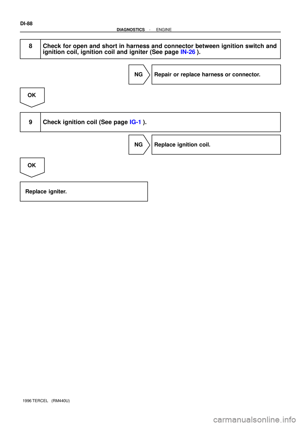
8 Check for open and short in harness and connector between ignition switch and
ignition coil, ignition coil and igniter (See page IN-26).
NG Repair or replace harness or connector.
OK
9 Check ignition coil (See page IG-1).
NG Replace ignition coil.
OK
Replace igniter.
Page 272 of 1202
A15734
- DIAGNOSTICSENGINE
DI-97
1996 TERCEL (RM440U)
ECM Power Source Circuit
CIRCUIT DESCRIPTION
When the ignition switch is turned ON, battery positive voltage is applied to the coil, closing the contacts of
the EFI main relay and supplying power to the terminal +B of the ECM.
WIRING DIAGRAM
DI4LL-02
Page 275 of 1202
A15736
DI-100
- DIAGNOSTICSENGINE
1996 TERCEL (RM440U)
Fuel Pump Control Circuit
CIRCUIT DESCRIPTION
In the diagram below, when the engine is cranked, current flows from terminal ST of the ignition switch to
the starter relay coil and also current flows to terminal STA of ECM (STA signal).
When the STA signal and NE signal are input to the ECM, Tr is turned ON, current flows to coil of the circuit
opening relay, the relay switches on, power is supplied to the fuel pump and the fuel pump operates.
While the NE signal is generated (engine running), the ECM keeps Tr ON (circuit opening relay ON) and the
fuel pump also keeps operating.
DI4LM-02
Page 425 of 1202
EM0KB-06
- ENGINE MECHANICALCOMPRESSION
EM-3
424 Author�: Date�:
1996 TERCEL (RM440U)
COMPRESSION
INSPECTION
HINT:
If there is lack of power, excessive oil consumption or poor fuel
economy, measure the compression pressure.
1. WARM UP AND STOP ENGINE
Allow the engine to warm up to normal operating temperature.
2. REMOVE SPARK PLUGS (See page IG-1)
3. CHECK CYLINDER COMPRESSION PRESSURE
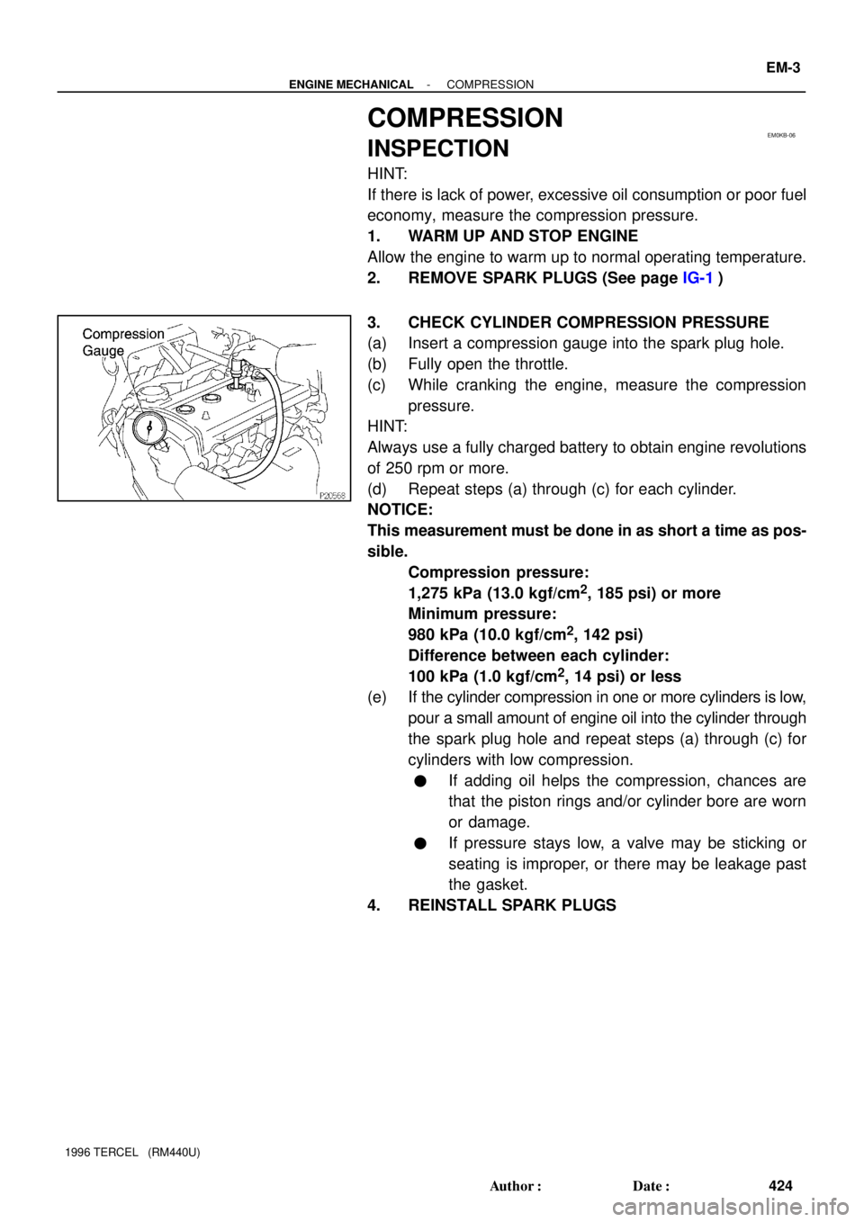
(a) Insert a compression gauge into the spark plug hole.
(b) Fully open the throttle.
(c) While cranking the engine, measure the compression
pressure.
HINT:
Always use a fully charged battery to obtain engine revolutions
of 250 rpm or more.
(d) Repeat steps (a) through (c) for each cylinder.
NOTICE:
This measurement must be done in as short a time as pos-
sible.
Compression pressure:
1,275 kPa (13.0 kgf/cm
2, 185 psi) or more
Minimum pressure:
980 kPa (10.0 kgf/cm
2, 142 psi)
Difference between each cylinder:
100 kPa (1.0 kgf/cm
2, 14 psi) or less
(e) If the cylinder compression in one or more cylinders is low,
pour a small amount of engine oil into the cylinder through
the spark plug hole and repeat steps (a) through (c) for
cylinders with low compression.
�If adding oil helps the compression, chances are
that the piston rings and/or cylinder bore are worn
or damage.
�If pressure stays low, a valve may be sticking or
seating is improper, or there may be leakage past
the gasket.
4. REINSTALL SPARK PLUGS
Page 426 of 1202
EM0KA-05
P20168
EM-4
- ENGINE MECHANICALVALVE CLEARANCE
425 Author�: Date�:
1996 TERCEL (RM440U)
VALVE CLEARANCE
INSPECTION
HINT:
Inspect and adjust the valve clearance when the engine is cold.
1. DISCONNECT PCV HOSES FROM CYLINDER HEAD
COVER
2. REMOVE HIGH- TENSION CORDS AND IGNITION
COILS FROM SPARK PLUGS
3. REMOVE CYLINDER HEAD COVER
(a) Remove the oil filler cap.
(b) Remove the 5 cap nuts and seal washers.
(c) Pry out the cylinder head cover, and remove the cover
and gasket.
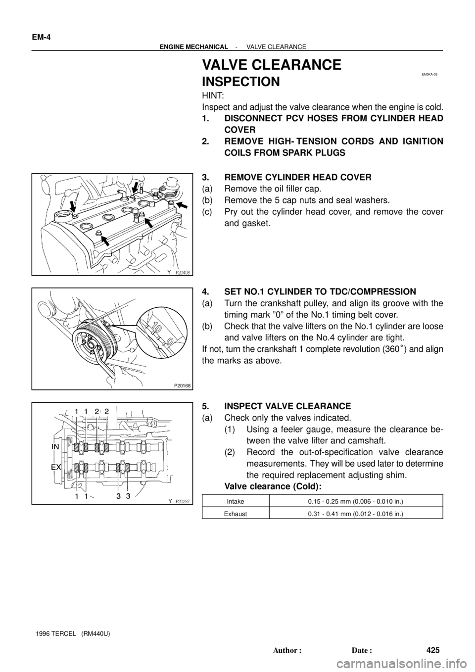
4. SET NO.1 CYLINDER TO TDC/COMPRESSION
(a) Turn the crankshaft pulley, and align its groove with the
timing mark º0º of the No.1 timing belt cover.
(b) Check that the valve lifters on the No.1 cylinder are loose
and valve lifters on the No.4 cylinder are tight.
If not, turn the crankshaft 1 complete revolution (360°) and align
the marks as above.
5. INSPECT VALVE CLEARANCE
(a) Check only the valves indicated.
(1) Using a feeler gauge, measure the clearance be-
tween the valve lifter and camshaft.
(2) Record the out-of-specification valve clearance
measurements. They will be used later to determine
the required replacement adjusting shim.
Valve clearance (Cold):
Intake0.15 - 0.25 mm (0.006 - 0.010 in.)
Exhaust0.31 - 0.41 mm (0.012 - 0.016 in.)
Page 428 of 1202
EM0494
P20156
SST(A)
SST(B)
EM-6
- ENGINE MECHANICALVALVE CLEARANCE
427 Author�: Date�:
1996 TERCEL (RM440U)
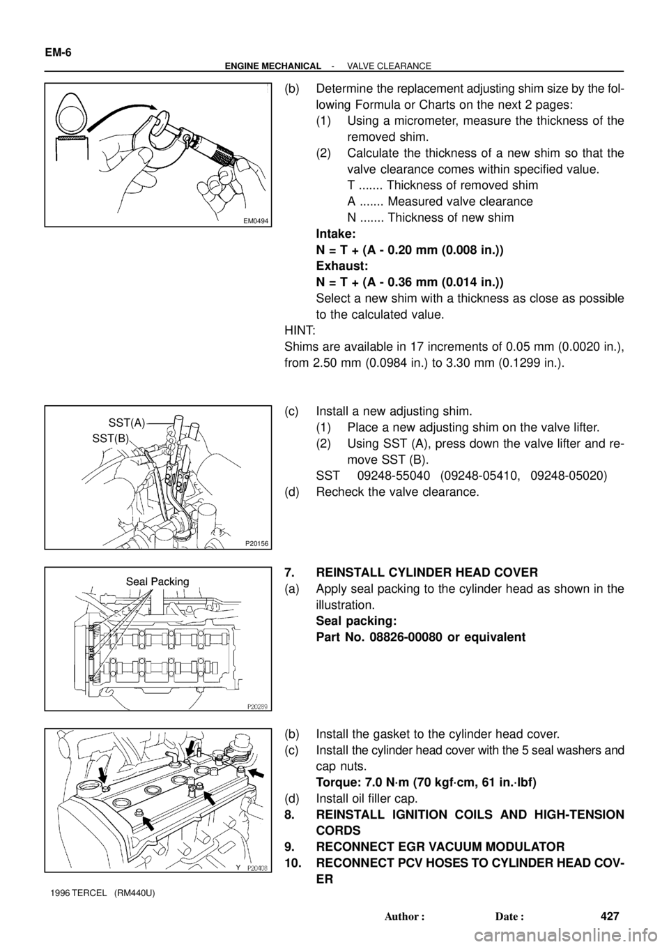
(b) Determine the replacement adjusting shim size by the fol-
lowing Formula or Charts on the next 2 pages:
(1) Using a micrometer, measure the thickness of the
removed shim.
(2) Calculate the thickness of a new shim so that the
valve clearance comes within specified value.
T ....... Thickness of removed shim
A ....... Measured valve clearance
N ....... Thickness of new shim
Intake:
N = T + (A - 0.20 mm (0.008 in.))
Exhaust:
N = T + (A - 0.36 mm (0.014 in.))
Select a new shim with a thickness as close as possible
to the calculated value.
HINT:
Shims are available in 17 increments of 0.05 mm (0.0020 in.),
from 2.50 mm (0.0984 in.) to 3.30 mm (0.1299 in.).
(c) Install a new adjusting shim.
(1) Place a new adjusting shim on the valve lifter.
(2) Using SST (A), press down the valve lifter and re-
move SST (B).
SST 09248-55040 (09248-05410, 09248-05020)
(d) Recheck the valve clearance.
7. REINSTALL CYLINDER HEAD COVER
(a) Apply seal packing to the cylinder head as shown in the
illustration.
Seal packing:
Part No. 08826-00080 or equivalent
(b) Install the gasket to the cylinder head cover.
(c) Install the cylinder head cover with the 5 seal washers and
cap nuts.
Torque: 7.0 N´m (70 kgf´cm, 61 in.´lbf)
(d) Install oil filler cap.
8. REINSTALL IGNITION COILS AND HIGH-TENSION
CORDS
9. RECONNECT EGR VACUUM MODULATOR
10. RECONNECT PCV HOSES TO CYLINDER HEAD COV-
ER
Page 434 of 1202
EM1OD-01
P20154
Oil Pan
P20153
Ground Strap
P20536
Timing Mark
P20159
EM-12
- ENGINE MECHANICALTIMING BELT
1996 TERCEL (RM440U)
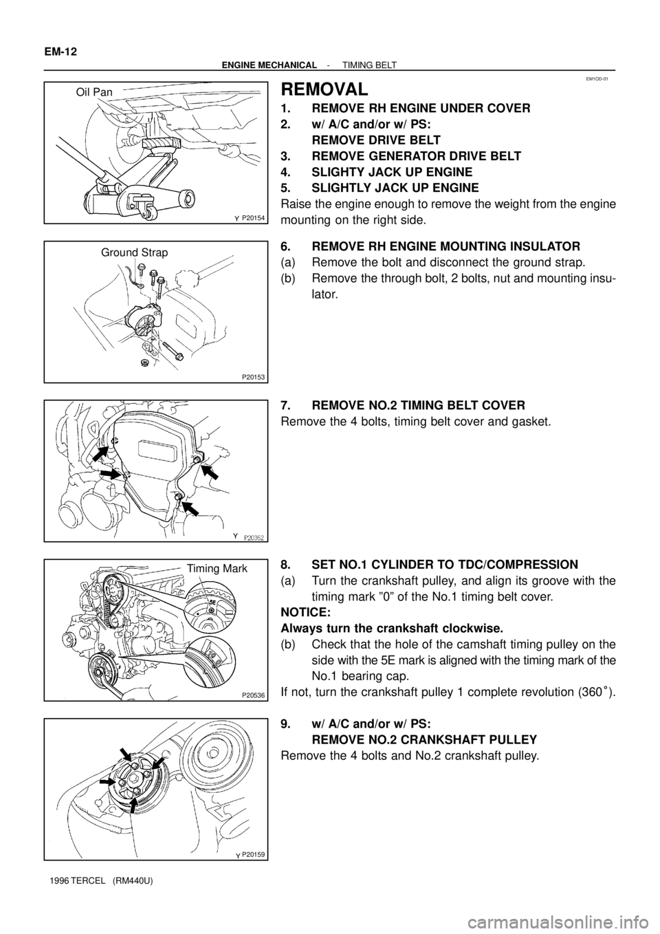
REMOVAL
1. REMOVE RH ENGINE UNDER COVER
2. w/ A/C and/or w/ PS:
REMOVE DRIVE BELT
3. REMOVE GENERATOR DRIVE BELT
4. SLIGHTY JACK UP ENGINE
5. SLIGHTLY JACK UP ENGINE
Raise the engine enough to remove the weight from the engine
mounting on the right side.
6. REMOVE RH ENGINE MOUNTING INSULATOR
(a) Remove the bolt and disconnect the ground strap.
(b) Remove the through bolt, 2 bolts, nut and mounting insu-
lator.
7. REMOVE NO.2 TIMING BELT COVER
Remove the 4 bolts, timing belt cover and gasket.
8. SET NO.1 CYLINDER TO TDC/COMPRESSION
(a) Turn the crankshaft pulley, and align its groove with the
timing mark º0º of the No.1 timing belt cover.
NOTICE:
Always turn the crankshaft clockwise.
(b) Check that the hole of the camshaft timing pulley on the
side with the 5E mark is aligned with the timing mark of the
No.1 bearing cap.
If not, turn the crankshaft pulley 1 complete revolution (360°).
9. w/ A/C and/or w/ PS:
REMOVE NO.2 CRANKSHAFT PULLEY
Remove the 4 bolts and No.2 crankshaft pulley.