Page 594 of 1202

CO18A-01
CO1242
Radiator Cap Tester
Radiator Cap
30° or More
- COOLINGRADIATOR
CO-13
1996 TERCEL (RM440U)
ON-VEHICLE INSPECTION
1. REMOVE RADIATOR CAP
CAUTION:
To avoid the danger of being burned, do not remove the ra-
diator cap while the engine and radiator are still hot, as fluid
and steam can be blown out under pressure.
2. INSPECT RADIATOR CAP
NOTICE:
�If the radiator cap has contaminations, always rinse
it with water.
�Before using a radiator cap tester, wet the relief valve
and pressure valve with engine coolant or water.
�When performing steps (a) and (b) below, keep the
tester at an angle of over 30° above the horizontal.
(a) Using a radiator cap tester, slowly pump the tester and
check that air is coming from the vacuum valve.
Pump speed: 1 push/3 seconds or more
NOTICE:
Push the pump at a constant speed.
If air is not coming from the vacuum valve, replace the radiator
cap.
(b) Pump the tester and measure the relief valve opening
pressure.
Pump speed: 1 push within 1 second
NOTICE:
This pump speed is for the first pump only (in order to close
the vacuum valve). After this, the pump speed can be re-
duced.
Standard opening pressure:
74 - 103 kPa (0.75 - 1.05 kgf/cm
2, 10.7 - 14.9 psi)
HINT:
Use the tester's maximum reading as the opening pressure.
If the opening pressure is less than minimum, replace the radia-
tor cap.
3. INSPECT COOLING SYSTEM FOR LEAKS
(a) Fill the radiator with coolant and attach a radiator cap tes-
ter.
(b) Warm up the engine.
(c) Pump it to 118 kPa (1.2 kgf/cm
2, 17.1 psi), and check that
the pressure does not drop.
If the pressure drops, check the hoses, radiator or water pump
for leaks. If no external leaks are found, check the heater core,
cylinder block and head.
4. REINSTALL RADIATOR CAP
Page 948 of 1202

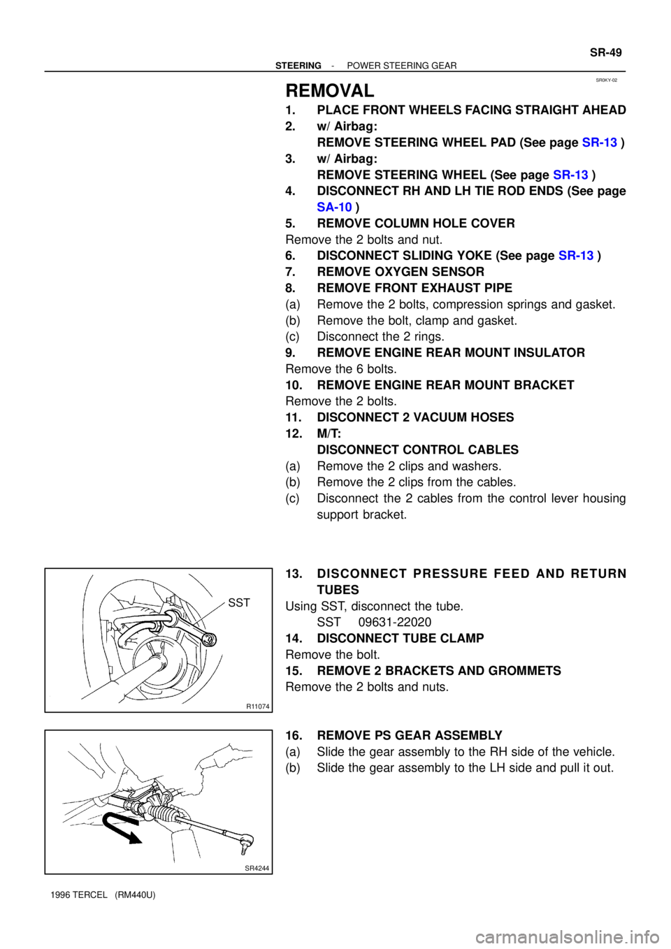
SR0KY-02
R11074
SST
SR4244
- STEERINGPOWER STEERING GEAR
SR-49
1996 TERCEL (RM440U)
REMOVAL
1. PLACE FRONT WHEELS FACING STRAIGHT AHEAD
2. w/ Airbag:
REMOVE STEERING WHEEL PAD (See page SR-13)
3. w/ Airbag:
REMOVE STEERING WHEEL (See page SR-13)
4. DISCONNECT RH AND LH TIE ROD ENDS (See page
SA-10)
5. REMOVE COLUMN HOLE COVER
Remove the 2 bolts and nut.
6. DISCONNECT SLIDING YOKE (See page SR-13)
7. REMOVE OXYGEN SENSOR
8. REMOVE FRONT EXHAUST PIPE
(a) Remove the 2 bolts, compression springs and gasket.
(b) Remove the bolt, clamp and gasket.
(c) Disconnect the 2 rings.
9. REMOVE ENGINE REAR MOUNT INSULATOR
Remove the 6 bolts.
10. REMOVE ENGINE REAR MOUNT BRACKET
Remove the 2 bolts.
11. DISCONNECT 2 VACUUM HOSES
12. M/T:
DISCONNECT CONTROL CABLES
(a) Remove the 2 clips and washers.
(b) Remove the 2 clips from the cables.
(c) Disconnect the 2 cables from the control lever housing
support bracket.
13. DISCONNECT PRESSURE FEED AND RETURN
TUBES
Using SST, disconnect the tube.
SST 09631-22020
14. DISCONNECT TUBE CLAMP
Remove the bolt.
15. REMOVE 2 BRACKETS AND GROMMETS
Remove the 2 bolts and nuts.
16. REMOVE PS GEAR ASSEMBLY
(a) Slide the gear assembly to the RH side of the vehicle.
(b) Slide the gear assembly to the LH side and pull it out.
Page 961 of 1202

SR0L2-03
R11193
R13112
Fulcrum
Length
SST
Z14367
B AB
B
BB
SR-62
- STEERINGPOWER STEERING GEAR
1996 TERCEL (RM440U)
INSTALLATION
1. INSTALL PS GEAR ASSEMBLY
Install the gear assembly from the LH of the vehicle.
NOTICE:
Do not damage the turn pressure tubes.
2. INSTALL 2 GROMMETS AND BRACKETS
Torque the 2 bolts and nuts.
Torque: 58 N´m (590 kgf´cm, 43 ft´lbf)
3. CONNECT PRESSURE FEED AND RETURN TUBES
Using SST, connect the tube.
SST 09631-22020
Torque: 36 N´m (366 kgf´cm, 27 ft´lbf)
HINT:
�Use a torque wrench with a fulcrum length of 300 mm
(11.81 in.).
�This torque value is effective in case that SST is parallel
to a torque wrench.
4. CONNECT TUBE CLAMP
Torque the bolt.
Torque: 13 N´m (130 kgf´cm, 9 ft´lbf)
5. M/T:
CONNECT CONTROL CABLES
(a) Connect the 2 cables to the control lever housing.
(b) Install the 2 clips to the cables.
(c) Install the 2 clips and washers.
6. CONNECT 2 VACUUM HOSES
7. INSTALL ENGINE REAR MOUNT BRACKET
Torque the 2 bolts.
Torque: 48 N´m (490 kgf´cm, 35 ft´lbf)
8. INSTALL ENGINE REAR MOUNT INSULATOR
Torque the 6 bolts.
Torque:
Bolt A: 64 N´m (650 kgf´cm, 47 ft´lbf)
Bolt B: 78 N´m (800 kgf´cm, 58 ft´lbf)
Page 1140 of 1202

AC1DT-01
N13795
Quick Disconnect
Adapter
Charging
Service ValveHose
N13794
Vacuum Pump
Vacuum Pump Adapter
N13791
Low Pressure
Service Valve
Vacuum Pump Adapter High Pressure
Service ValveManifold
Gauge
Set
- AIR CONDITIONINGAIR CONDITIONING SYSTEM
AC-1 1
1996 TERCEL (RM440U)
EVACUATING
1. CONNECT QUICK DISCONNECT ADAPTER TO
CHARGING HOSES
2. REMOVE CAPS FROM SERVICE VALVES ON RE-
FRIGERANT LINES
3. SET ON MANIFOLD GAUGE SET
(a) Close both hand valves of manifold gauge set.
(b) Connect the quick disconnect adapters to the service
valves.
4. EVACUATE AIR FROM REFRIGERATION SYSTEM
(a) Connect the vacuum pump adapter to the vacuum pump.
(b) Connect the center hose of the manifold gauge set to the
vacuum pump adapter.
(c) Open both the high and low hand valves and run the vacu-
um pump.
(d) After 10 minutes or more, check that the low pressure
gauge indicates 750 mmHg (30 in. Hg) or more.
HINT:
If the reading is 750 mmHg (30 in. Hg) or more, close both hand
valves of manifold gauge set and stop the vacuum pump.
Check the system for leaks and repair if necessary.
(e) Close both the high and low hand valves and stop the vac-
uum pump.
(f) Leave the system in this condition for 5 minutes or more
and check that there is no gauge indicator.
Page:
< prev 1-8 9-16 17-24