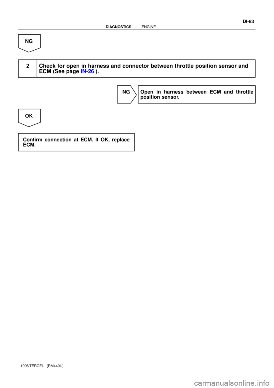
Page 207 of 1202

P24296
Throttle Position
Sensor
E2 VTAECM
VC
- DIAGNOSTICSENGINE
DI-33
1996 TERCEL (RM440U)
DTC P0120 Throttle/Pedal Position Sensor/Switch ºAº
Circuit Malfunction
CIRCUIT DESCRIPTION
The throttle position sensor is mounted in the throttle body and
detects the throttle valve opening angle. When the throttle valve
is fully closed, a voltage of approximately 0.3 - 0.8 V is applied
to terminal VTA of the ECM. The voltage applied to the terminal
VTA of the ECM increases in proportion to the opening angle
of the throttle valve and becomes approximately 3.2 - 4.9 V
when the throttle valve is fully opened. The ECM judges the ve-
hicle driving conditions from these signals input from terminal
VTA and uses them as one of the conditions for deciding the
air-fuel ratio correction, power increases correction and fuel-
cut control etc.
DTC No.DTC Detection ConditionTrouble Area
P0120
Condition (a) or (b) continues:
(a) VTA < 0.1 V
(b) VTA > 4.9 V�Open or short in throttle position sensor circuit
�Throttle position sensor
�ECM
HINT:
After confirming DTC P0120, use the OBD II scan tool or TOYOTA hand-held tester to confirm the throttle
valve opening percentage.
Throttle valve opening position expressed as percentageTblAThrottle valve fully closedThrottle valve fully openTrouble Area
0 %0 %VC line open
VTA line open or short
100 %100 %E2 line open
DI1E8-08
Page 208 of 1202
A15689
FI7052
DI-34
- DIAGNOSTICSENGINE
1996 TERCEL (RM440U)
WIRING DIAGRAM
INSPECTION PROCEDURE
HINT:
If DTC P0105, P0110, P0120 are output simultaneously, E2 (sensor ground) may be open.
1 Connect OBD II scan tool or TOYOTA hand-held tester and read throttle valve
opening percentage.
PREPARATION:
(a) Remove the fuse cover on the instrument panel.
(b) Connect the OBD II scan tool or TOYOTA hand-held tes-
ter to the DLC3.
(c) Turn the ignition switch ON and OBD II scan tool or TOY-
OTA hand-held tester main switch ON.
CHECK:
Read the throttle valve opening percentage.
OK:
Throttle valveThrottle valve opening
position expressed as percentage
Fully openApprox. 70 %
Fully closedApprox. 10 %
OK Check for intermittent problems
(See page DI-3).
NG
Page 209 of 1202
A00369
1 (+) ON
S03529 BE6653A00854
ON
VTA (+) E2 (-)
- DIAGNOSTICSENGINE
DI-35
1996 TERCEL (RM440U)
2 Check voltage between terminal 1 of wire harness side connector and body
ground.
PREPARATION:
(a) Disconnect the throttle position sensor connector.
(b) Turn the ignition switch ON.
CHECK:
Measure the voltage between terminal 1 of wire harness side
connector and the body ground.
OK:
Voltage: 4.5 - 5.5 V
NG Go to step 5.
OK
3 Check throttle position sensor (See page MF-26).
NG Replace throttle position sensor.
OK
4 Check voltage between terminals VTA and E2 of ECM connector.
PREPARATION:
(a) Remove the lower finish panel.
(b) Turn the ignition switch ON.
CHECK:
Measure the voltage between terminals VTA and E2 of the ECM
connector.
OK:
Throttle ValveVoltage
Fully closed0.3 - 1.0 V
Fully open3.2 - 4.9 V
NG Check for open and short in harness and con-
nector between ECM and throttle position sen-
sor (VTA or E2 line) (See page IN-26).
OK
Page 211 of 1202
- DIAGNOSTICSENGINE
DI-37
1996 TERCEL (RM440U)
DTC P0121 Throttle/Pedal Position Sensor/Switch ºAº
Circuit Range/Performance Problem
CIRCUIT DESCRIPTION
Refer to DTC P0120 on page DI-32.
DTC No.DTC Detection ConditionTrouble Area
P0121
While the vehicle speed drops from 30 km/h (19 mph)
or more to 0 km/h (0 mph), the output value of the
throttle position sensor is out of the applicable range
(2 trip detection logic)
�Throttle position sensor
INSPECTION PROCEDURE
1 Are there any other codes (besides DTC P0121) being output?
YES Go to relevant DTC chart.
NO
Replace throttle position sensor.
DI1E9-06
Page 256 of 1202
A15717
- DIAGNOSTICSENGINE
DI-81
1996 TERCEL (RM440U)
DTC P0510 Closed Throttle Position Switch Malfunction
CIRCUIT DESCRIPTION
Refer to DTC P0120 on page DI-33.
DTC No.DTC Detection ConditionTrouble Area
P0510Closed throttle position switch does not turn ON even once
when vehicle is driven (2 trip detection logic)�Open in closed throttle position switch circuit
�Closed throttle position switch
�ECM
HINT:
After confirming DTC P0510, use the TOYOTA hand-held tester to confirm the closed throttle position switch
signal from the CURRENT DATA.
Throttle ValveClosed Throttle Position Switch SignalMalfunction
Fully closedOFFOpen circuit
Fully openONShort circuit
WIRING DIAGRAM
Refer to DTC P0120 on page DI-33.
INSPECTION PROCEDURE
HINT:
If DTCs P0110, P0115 and P0120 are output simultaneously, E2 (sensor ground) may be open.
TOYOTA hand-held tester:
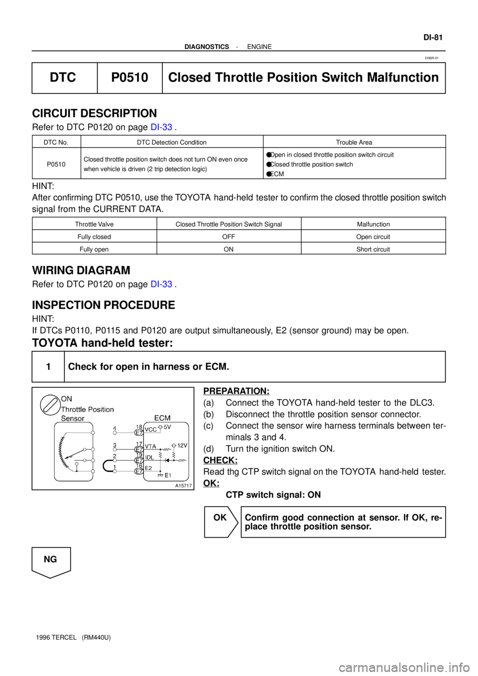
1 Check for open in harness or ECM.
PREPARATION:
(a) Connect the TOYOTA hand-held tester to the DLC3.
(b) Disconnect the throttle position sensor connector.
(c) Connect the sensor wire harness terminals between ter-
minals 3 and 4.
(d) Turn the ignition switch ON.
CHECK:
Read thg CTP switch signal on the TOYOTA hand-held tester.
OK:
CTP switch signal: ON
OK Confirm good connection at sensor. If OK, re-
place throttle position sensor.
NG
DI95R-01
Page 257 of 1202
A15718
A15719
DI-82
- DIAGNOSTICSENGINE
1996 TERCEL (RM440U)
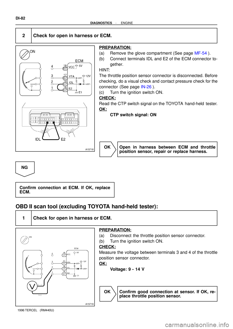
2 Check for open in harness or ECM.
PREPARATION:
(a) Remove the glove compartment (See page MF-54).
(b) Connect terminals IDL and E2 of the ECM connector to-
gether.
HINT:
The throttle position sensor connector is disconnected. Before
checking, do a visual check and contact pressure check for the
connector (See page IN-26).
(c) Turn the ignition switch ON.
CHECK:
Read the CTP switch signal on the TOYOTA hand-held tester.
OK:
CTP switch signal: ON
OK Open in harness between ECM and throttle
position sensor, repair or replace harness.
NG
Confirm connection at ECM. If OK, replace
ECM.
OBD II scan tool (excluding TOYOTA hand-held tester):
1 Check for open in harness or ECM.
PREPARATION:
(a) Disconnect the throttle position sensor connector.
(b) Turn the ignition switch ON.
CHECK:
Measure the voltage between terminals 3 and 4 of the throttle
position sensor connector.
OK:
Voltage: 9 - 14 V
OK Confirm good connection at sensor. If OK, re-
place throttle position sensor.
Page 258 of 1202
- DIAGNOSTICSENGINE
DI-83
1996 TERCEL (RM440U)
NG
2 Check for open in harness and connector between throttle position sensor and
ECM (See page IN-26).
NG Open in harness between ECM and throttle
position sensor.
OK
Confirm connection at ECM. If OK, replace
ECM.
Page 446 of 1202
EG0023
EM-24
- ENGINE MECHANICALCYLINDER HEAD
1996 TERCEL (RM440U)
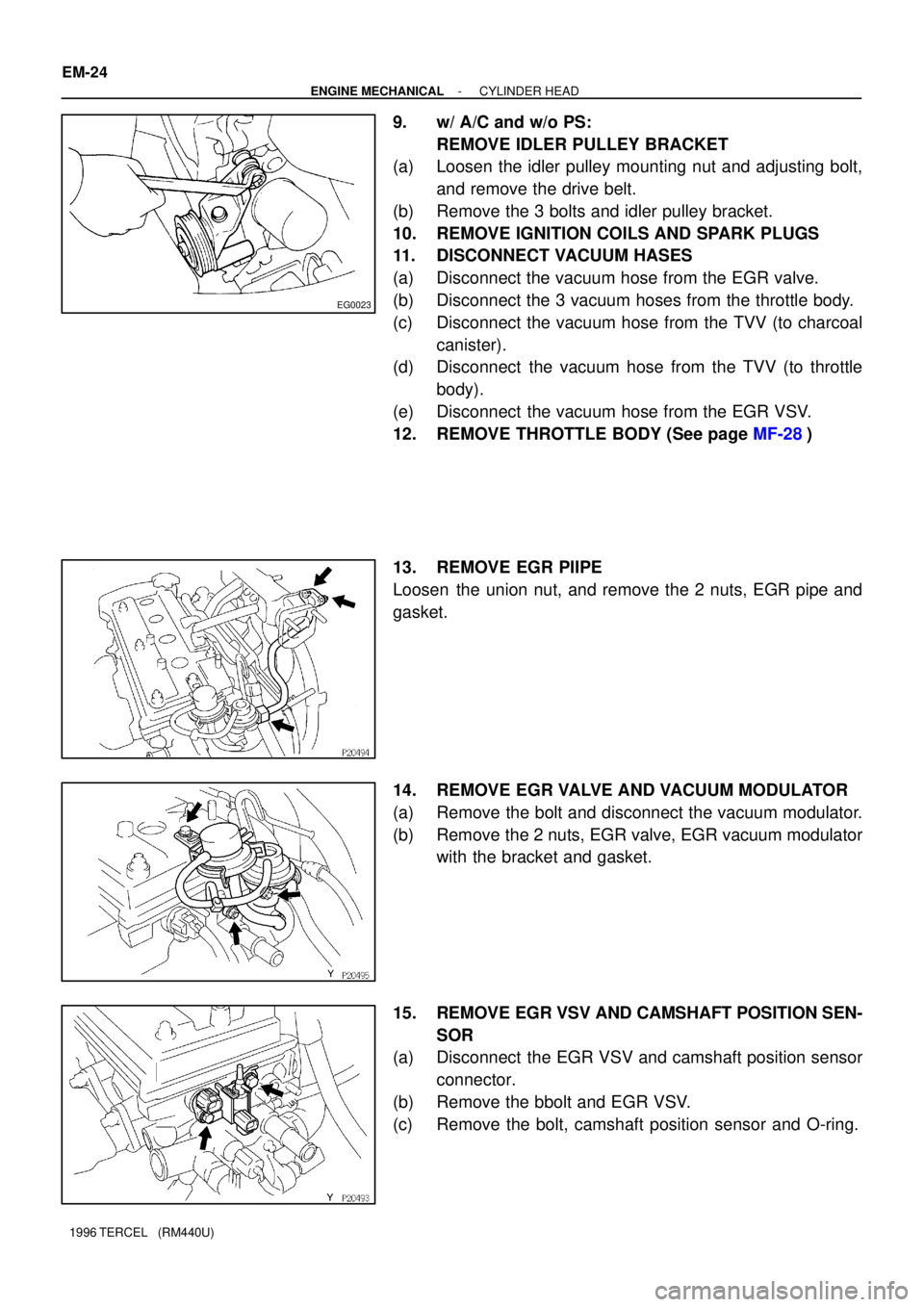
9. w/ A/C and w/o PS:
REMOVE IDLER PULLEY BRACKET
(a) Loosen the idler pulley mounting nut and adjusting bolt,
and remove the drive belt.
(b) Remove the 3 bolts and idler pulley bracket.
10. REMOVE IGNITION COILS AND SPARK PLUGS
11. DISCONNECT VACUUM HASES
(a) Disconnect the vacuum hose from the EGR valve.
(b) Disconnect the 3 vacuum hoses from the throttle body.
(c) Disconnect the vacuum hose from the TVV (to charcoal
canister).
(d) Disconnect the vacuum hose from the TVV (to throttle
body).
(e) Disconnect the vacuum hose from the EGR VSV.
12. REMOVE THROTTLE BODY (See page MF-28)
13. REMOVE EGR PIIPE
Loosen the union nut, and remove the 2 nuts, EGR pipe and
gasket.
14. REMOVE EGR VALVE AND VACUUM MODULATOR
(a) Remove the bolt and disconnect the vacuum modulator.
(b) Remove the 2 nuts, EGR valve, EGR vacuum modulator
with the bracket and gasket.
15. REMOVE EGR VSV AND CAMSHAFT POSITION SEN-
SOR
(a) Disconnect the EGR VSV and camshaft position sensor
connector.
(b) Remove the bbolt and EGR VSV.
(c) Remove the bolt, camshaft position sensor and O-ring.