Page 453 of 1202
EM0K0-05
P20381
P20380
P20350
P20353
EG0031
- ENGINE MECHANICALCYLINDER HEAD
EM-31
1996 TERCEL (RM440U)
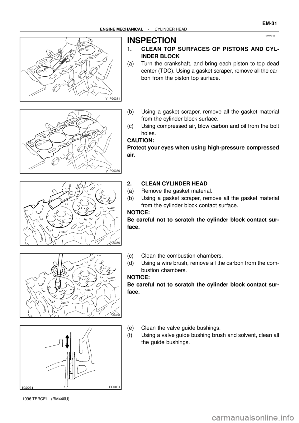
INSPECTION
1. CLEAN TOP SURFACES OF PISTONS AND CYL-
INDER BLOCK
(a) Turn the crankshaft, and bring each piston to top dead
center (TDC). Using a gasket scraper, remove all the car-
bon from the piston top surface.
(b) Using a gasket scraper, remove all the gasket material
from the cylinder block surface.
(c) Using compressed air, blow carbon and oil from the bolt
holes.
CAUTION:
Protect your eyes when using high-pressure compressed
air.
2. CLEAN CYLINDER HEAD
(a) Remove the gasket material.
(b) Using a gasket scraper, remove all the gasket material
from the cylinder block contact surface.
NOTICE:
Be careful not to scratch the cylinder block contact sur-
face.
(c) Clean the combustion chambers.
(d) Using a wire brush, remove all the carbon from the com-
bustion chambers.
NOTICE:
Be careful not to scratch the cylinder block contact sur-
face.
(e) Clean the valve guide bushings.
(f) Using a valve guide bushing brush and solvent, clean all
the guide bushings.
Page 455 of 1202
P20382
Z00052
Z00054
44.5°
EM0181
Margin Thickness
- ENGINE MECHANICALCYLINDER HEAD
EM-33
1996 TERCEL (RM440U)
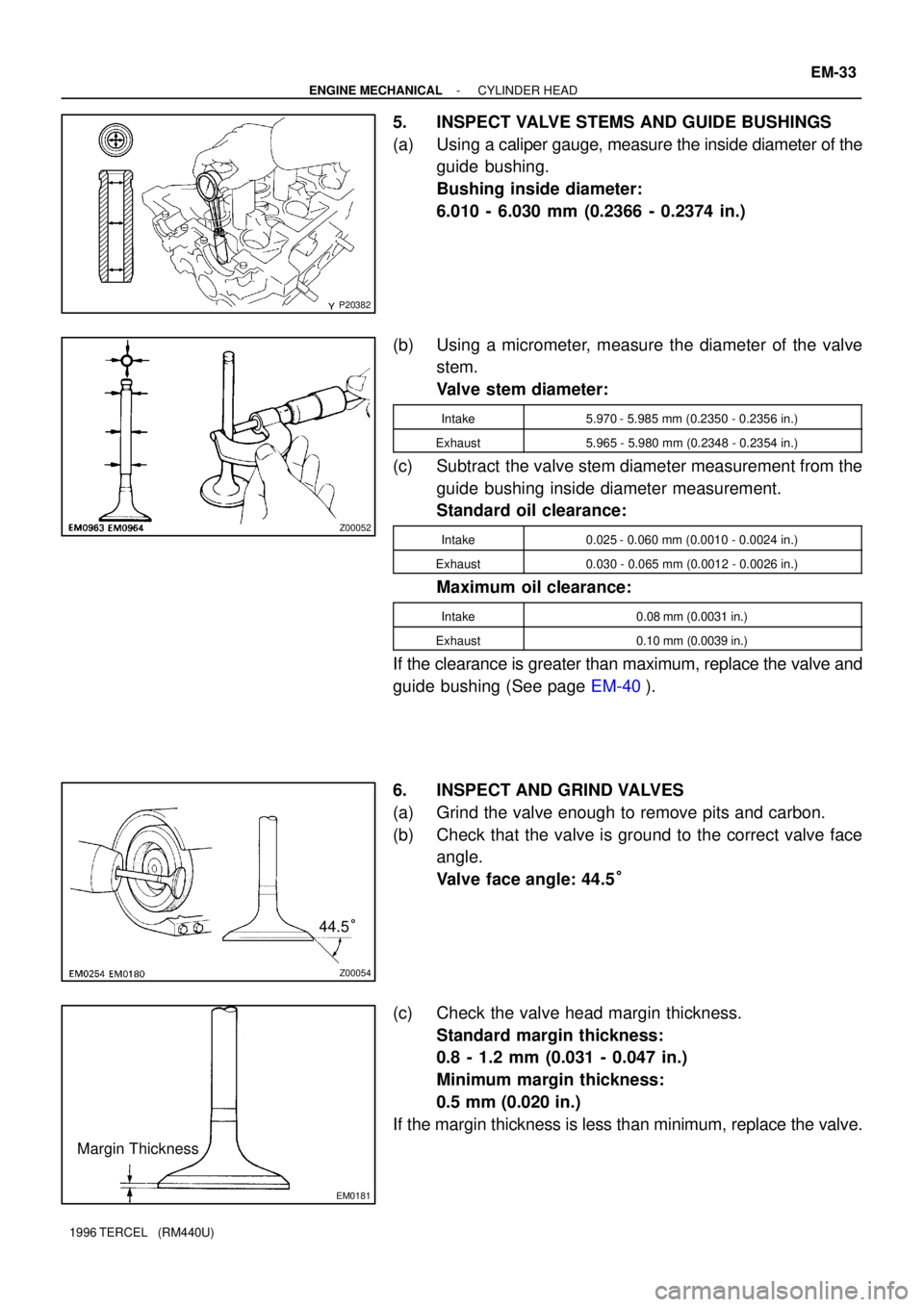
5. INSPECT VALVE STEMS AND GUIDE BUSHINGS
(a) Using a caliper gauge, measure the inside diameter of the
guide bushing.
Bushing inside diameter:
6.010 - 6.030 mm (0.2366 - 0.2374 in.)
(b) Using a micrometer, measure the diameter of the valve
stem.
Valve stem diameter:
Intake5.970 - 5.985 mm (0.2350 - 0.2356 in.)
Exhaust5.965 - 5.980 mm (0.2348 - 0.2354 in.)
(c) Subtract the valve stem diameter measurement from the
guide bushing inside diameter measurement.
Standard oil clearance:
Intake0.025 - 0.060 mm (0.0010 - 0.0024 in.)
Exhaust0.030 - 0.065 mm (0.0012 - 0.0026 in.)
Maximum oil clearance:
Intake0.08 mm (0.0031 in.)
Exhaust0.10 mm (0.0039 in.)
If the clearance is greater than maximum, replace the valve and
guide bushing (See page EM-40).
6. INSPECT AND GRIND VALVES
(a) Grind the valve enough to remove pits and carbon.
(b) Check that the valve is ground to the correct valve face
angle.
Valve face angle: 44.5°
(c) Check the valve head margin thickness.
Standard margin thickness:
0.8 - 1.2 mm (0.031 - 0.047 in.)
Minimum margin thickness:
0.5 mm (0.020 in.)
If the margin thickness is less than minimum, replace the valve.
Page 492 of 1202
EM0JQ-06
EM9411
EM9412
P20480
SST
P20478
SST
P20477
12 mm
Hexagon
Wrench EM-70
- ENGINE MECHANICALCYLINDER BLOCK
1996 TERCEL (RM440U)
DISASSEMBLY
1. M/T:
REMOVE CLUTCH COVER AND DISC
2. REMOVE FLYWHEEL (M/T) OR DRIVE PLATE (A/T)
3. REMOVE REAR END PLATE
4. INSTALL ENGINE TO ENGINE STAND FOR DIS-
ASSEMBLY
5. REMOVE TIMING BELT AND PULLEYS
6. REMOVE CYLINDER HEAD
7. REMOVE OIL DIPSTICK GUIDE AND GENERATOR
ADJUSTING BAR
8. REMOVE WATER PUMP WITH WATER INLET PIPE
9. REMOVE GENERATOR BRACKET
10. REMOVE KNOCK SENSOR
Using SST, remove the knock sensor.
SST 09816-30010
11. REMOVE RH ENGINE MOUNTING BRACKET
12. REMOVE OIL FILTER
13. REMOVE OIL PRESSURE SWITCH
Using SST, remove the oil pressure switch.
SST 09816-30010
14. REMOVE OIL PUMP AND PRESSURE REGULATOR
VA LV E
15. REMOVE OIL FILTER UNION
Using a 12 mm hexagon wrench, remove the oil filter union.
Page 512 of 1202
P20750
P20480
SST
P20545
EM9412
EM7333
EM-90
- ENGINE MECHANICALCYLINDER BLOCK
1996 TERCEL (RM440U)
15. INSTALL RH ENGINE MOUNTING BRACKET
Torque: 58 N´m (590 kgf´cm, 43 ft´lbf)
16. INSTALL KNOCK SENSOR
Using SST, install the knock sensor.
SST 09816-30010
Torque: 45 N´m (450 kgf´cm, 33 ft´lbf)
17. INSTALL GENERATOR BRACKET
Torque: 24 N´m (240 kgf´cm, 18 ft´lbf)
18. INSTALL WATER PUMP WITH WATER INLET PIPE
19. INSTALL OIL DIPSTICK GUIDE AND GENERATOR AD-
JUSTING BAR
20. INSTALL CYLINDER HEAD
21. INSTALL TIMING BELT AND PULLEYS
22. REMOVE ENGINE STAND
23. INSTALL REAR END PLATE
Torque: 10 N´m (100 kgf´cm, 7 ft´lbf)
24. M/T:
INSTALL FLYWHEEL
(a) Apply adhesive to 2 or 3 threads of new mounting bolt
end.
Adhesive:
Part No. 08833-00070, THREE BOND 1324 or
equivalent
Page 585 of 1202
CO0HT-04
P21028
(b)
(c)
(a)
P21132
(2)(1)(b)
(a)
P21130
P21029
CO-4
- COOLINGWATER PUMP
1996 TERCEL (RM440U)
REMOVAL
1. DRAIN ENGINE COOLANT
2. REMOVE GENERATOR
3. REMOVE INTAKE MANIFOLD STAY
(a) Disconnect the engine wire clamps from the intake man-
ifold stay.
(b) Remove the bolt, nut and intake manifold stay.
4. REMOVE WATER INLET PIPE
(a) Disconnect the water inlet hose.
(b) Disconnect the heater inlet hose.
(c) Disconnect the water bypass hose.
(d) Remove the bolt, water inlet pipe and O-ring.
5. REMOVE OIL DIPSTICK GUIDE AND GENERATOR
ADJUSTING BAR
(a) Disconnect the engine wire clamp.
(b) Disconnect the connector clamp for crankshaft position
sensor.
(c) Remove the oil dipstick.
(d) Remove the mounting bolt of the dipstick guide clamp and
generator adjusting bar.
(e) Pull out the dipstick guide. Plug the guide installation hole
of the oil pump.
(f) Remove the O-ring from the dipstick guide.
6. REMOVE WATER PUMP
Remove the bolt, 2 nuts and water pump.
Page 587 of 1202
CO0Y1-02
P21031
CO1231 CORRECT WRONG
Seal Diameter
2 - 3 mm
(0.08 - 0.12 in.)
Seal Packing
P21131
New
O-Ring CO-6
- COOLINGWATER PUMP
1996 TERCEL (RM440U)
INSTALLATION
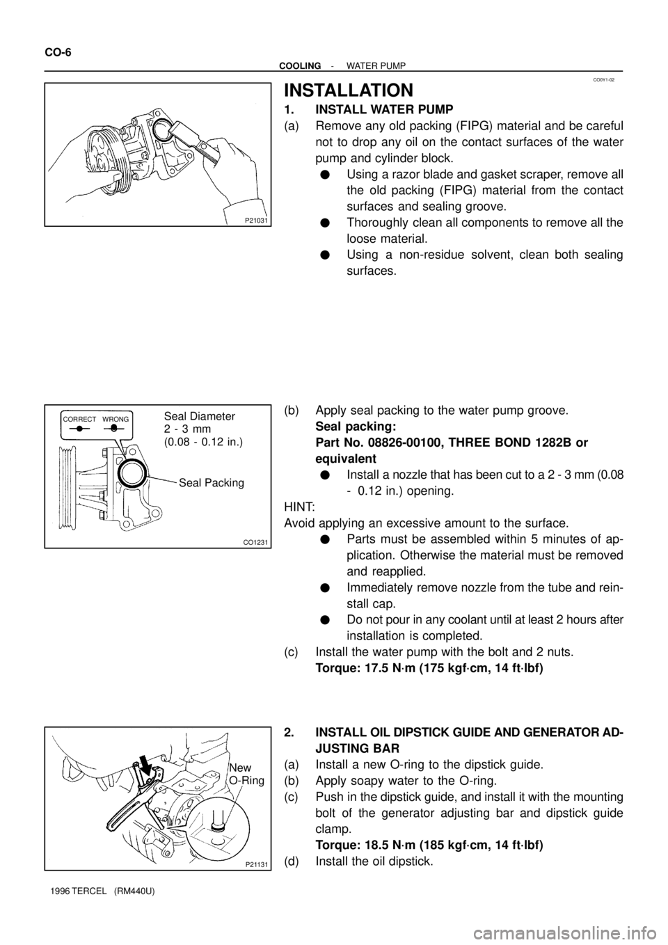
1. INSTALL WATER PUMP
(a) Remove any old packing (FIPG) material and be careful
not to drop any oil on the contact surfaces of the water
pump and cylinder block.
�Using a razor blade and gasket scraper, remove all
the old packing (FIPG) material from the contact
surfaces and sealing groove.
�Thoroughly clean all components to remove all the
loose material.
�Using a non-residue solvent, clean both sealing
surfaces.
(b) Apply seal packing to the water pump groove.
Seal packing:
Part No. 08826-00100, THREE BOND 1282B or
equivalent
�Install a nozzle that has been cut to a 2 - 3 mm (0.08
- 0.12 in.) opening.
HINT:
Avoid applying an excessive amount to the surface.
�Parts must be assembled within 5 minutes of ap-
plication. Otherwise the material must be removed
and reapplied.
�Immediately remove nozzle from the tube and rein-
stall cap.
�Do not pour in any coolant until at least 2 hours after
installation is completed.
(c) Install the water pump with the bolt and 2 nuts.
Torque: 17.5 N´m (175 kgf´cm, 14 ft´lbf)
2. INSTALL OIL DIPSTICK GUIDE AND GENERATOR AD-
JUSTING BAR
(a) Install a new O-ring to the dipstick guide.
(b) Apply soapy water to the O-ring.
(c) Push in the dipstick guide, and install it with the mounting
bolt of the generator adjusting bar and dipstick guide
clamp.
Torque: 18.5 N´m (185 kgf´cm, 14 ft´lbf)
(d) Install the oil dipstick.
Page 934 of 1202
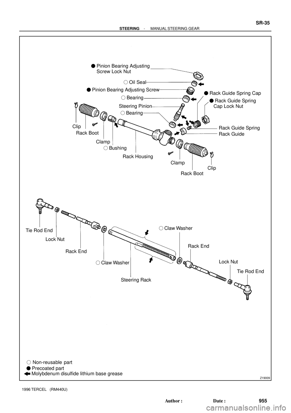
Z19009
� Non-reusable part
� Precoated part
Molybdenum disulfide lithium base grease Tie Rod End
Lock Nut
Rack End
� Claw Washer
Steering Rack Rack Housing � Bushing Clip
Clamp Rack Boot� Pinion Bearing Adjusting
Screw Lock Nut
� Rack Guide Spring Cap
� Rack Guide Spring
Cap Lock Nut
Rack Guide Rack Guide Spring � Oil Seal
� Pinion Bearing Adjusting Screw
� Bearing
Steering Pinion
� Bearing
Clamp
Rack Boot
Clip
� Claw Washer
Rack End
Lock Nut
Tie Rod End
- STEERINGMANUAL STEERING GEAR
SR-35
955 Author�: Date�:
1996 TERCEL (RM440U)
Page 942 of 1202
R12818Hexagon Wrench12°
R15481
SST
Z14313
Hexagon WrenchSST
R15482
Hexagon
Wrench SST
Fulcrum
Length
- STEERINGMANUAL STEERING GEAR
SR-43
1996 TERCEL (RM440U)
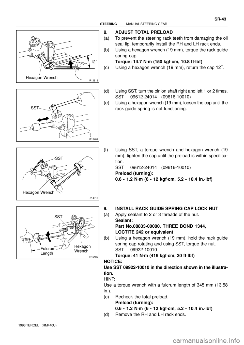
8. ADJUST TOTAL PRELOAD
(a) To prevent the steering rack teeth from damaging the oil
seal lip, temporarily install the RH and LH rack ends.
(b) Using a hexagon wrench (19 mm), torque the rack guide
spring cap.
Torque: 14.7 N´m (150 kgf´cm, 10.8 ft´lbf)
(c) Using a hexagon wrench (19 mm), return the cap 12°.
(d) Using SST, turn the pinion shaft right and left 1 or 2 times.
SST 09612-24014 (09616-10010)
(e) Using a hexagon wrench (19 mm), loosen the cap until the
rack guide spring is not functioning.
(f) Using SST, a torque wrench and hexagon wrench (19
mm), tighten the cap until the preload is within specifica-
tion.
SST 09612-24014 (09616-10010)
Preload (turning):
0.6 - 1.2 N´m (6 - 12 kgf´cm, 5.2 - 10.4 in.´lbf)
9. INSTALL RACK GUIDE SPRING CAP LOCK NUT
(a) Apply sealant to 2 or 3 threads of the nut.
Sealant:
Part No.08833-00080, THREE BOND 1344,
LOCTITE 242 or equivalent
(b) Using a hexagon wrench (19 mm), hold the rack guide
spring cap rotating and using SST, torque the nut.
SST 09922-10010
Torque: 41 N´m (419 kgf´cm, 30 ft´lbf)
NOTICE:
Use SST 09922-10010 in the direction shown in the illustra-
tion.
HINT:
Use a torque wrench with a fulcrum length of 345 mm (13.58
in.).
(c) Recheck the total preload.
Preload (turning):
0.6 - 1.2 N´m (6 - 12 kgf´cm, 5.2 - 10.4 in.´lbf)
(d) Remove the RH and LH rack ends.