Page 426 of 1202

VALVE CLEARANCE
INSPECTION
HINT:
Inspect and adjust the valve clearance when the engine is cold.
1.")
EM0KA-05
P20168
EM-4
- ENGINE MECHANICALVALVE CLEARANCE
425 Author�: Date�:
1996 TERCEL (RM440U)
VALVE CLEARANCE
INSPECTION
HINT:
Inspect and adjust the valve clearance when the engine is cold.
1. DISCONNECT PCV HOSES FROM CYLINDER HEAD
COVER
2. REMOVE HIGH- TENSION CORDS AND IGNITION
COILS FROM SPARK PLUGS
3. REMOVE CYLINDER HEAD COVER
(a) Remove the oil filler cap.
(b) Remove the 5 cap nuts and seal washers.
(c) Pry out the cylinder head cover, and remove the cover
and gasket.
4. SET NO.1 CYLINDER TO TDC/COMPRESSION
(a) Turn the crankshaft pulley, and align its groove with the
timing mark º0º of the No.1 timing belt cover.
(b) Check that the valve lifters on the No.1 cylinder are loose
and valve lifters on the No.4 cylinder are tight.
If not, turn the crankshaft 1 complete revolution (360°) and align
the marks as above.
5. INSPECT VALVE CLEARANCE
(a) Check only the valves indicated.
(1) Using a feeler gauge, measure the clearance be-
tween the valve lifter and camshaft.
(2) Record the out-of-specification valve clearance
measurements. They will be used later to determine
the required replacement adjusting shim.
Valve clearance (Cold):
Intake0.15 - 0.25 mm (0.006 - 0.010 in.)
Exhaust0.31 - 0.41 mm (0.012 - 0.016 in.)
Page 446 of 1202

9. w/ A/C and w/o PS:
REMOVE IDLER PULLEY BRACKET
(a) Loosen the idler pulley mounting nut and adjusting bolt,
and remove the drive")
EG0023
EM-24
- ENGINE MECHANICALCYLINDER HEAD
1996 TERCEL (RM440U)
9. w/ A/C and w/o PS:
REMOVE IDLER PULLEY BRACKET
(a) Loosen the idler pulley mounting nut and adjusting bolt,
and remove the drive belt.
(b) Remove the 3 bolts and idler pulley bracket.
10. REMOVE IGNITION COILS AND SPARK PLUGS
11. DISCONNECT VACUUM HASES
(a) Disconnect the vacuum hose from the EGR valve.
(b) Disconnect the 3 vacuum hoses from the throttle body.
(c) Disconnect the vacuum hose from the TVV (to charcoal
canister).
(d) Disconnect the vacuum hose from the TVV (to throttle
body).
(e) Disconnect the vacuum hose from the EGR VSV.
12. REMOVE THROTTLE BODY (See page MF-28)
13. REMOVE EGR PIIPE
Loosen the union nut, and remove the 2 nuts, EGR pipe and
gasket.
14. REMOVE EGR VALVE AND VACUUM MODULATOR
(a) Remove the bolt and disconnect the vacuum modulator.
(b) Remove the 2 nuts, EGR valve, EGR vacuum modulator
with the bracket and gasket.
15. REMOVE EGR VSV AND CAMSHAFT POSITION SEN-
SOR
(a) Disconnect the EGR VSV and camshaft position sensor
connector.
(b) Remove the bbolt and EGR VSV.
(c) Remove the bolt, camshaft position sensor and O-ring.
Page 475 of 1202

22. INSTALL EGR PIPE
Install a new gasket, sleeve ball and the EGR pipe with the
union nut and 2 nuts.
Torque:
Union nut
40")
EG0023
P20290
- ENGINE MECHANICALCYLINDER HEAD
EM-53
1996 TERCEL (RM440U)
22. INSTALL EGR PIPE
Install a new gasket, sleeve ball and the EGR pipe with the
union nut and 2 nuts.
Torque:
Union nut
40 N´m (400 kgf´cm, 29 in.´lbf)
Nut
30 N´m (300 kgf´cm, 22 in.´lbf)
23. INSTALL THROTTLE BODY (See page MF-32)
24. CONNECT VACUUM HOSES
(a) Connect the vacuum hose from the EGR valve.
(b) Connect the 3 vacuum hoses from the throttle body.
(c) Connect the vacuum hose from TVV (to charcoal canis-
ter).
(d) Connect the vacuum hose from the TVV (to throttle body).
(e) Connect the vacuum hose from the EGR VSV.
25. INSTALL IGNITION COILS AND SPARK PLUGS
26. w/ A/C and w/o PS:
INSTALL IDLER PULLEY BRACKET
(a) Install the idler pulley bracket with the 3 bolts.
Torque:
12 mm head bolt
27 N´m (275 kgf´cm, 20 ft´lbf)
14 mm head bolt
37 N´m (375 kgf´cm, 27 ft´lbf)
(b) Install and adjust the drive belt (See page AC-18).
27. w/ PS:
INSTALL PS PUMP BRACKET AND PS PUMP
(a) Install the PS pump bracket with the 3 bolts.
Torque: 44 N´m (440 kgf´cm, 32 ft´lbf)
(b) Temporarily install the PS pump and drive belt with the 2
bolts (See page SR-33).
(c) Adjust the belt tension (See page SR-3).
28. CONNECT FUEL HOSE
Connect the fuel inlet hose with the union bolt and 2 new gas-
kets.
Torque: 29 N´m (300 kgf´cm, 22 ft´lbf)
29. INSTALL AIR CLEANER ASSEMBLY WITH AIR IN-
TAKE CONNECTOR
30. INSTALL ACCELERATOR CABLE, AND ADJUST IT
31. A/T:
CONNECT THROTTLE CABLE, AND ADJUST IT
Page 531 of 1202

(d) Install the fuel inlet hose and SST (pressure gauge) to the
fuel filter outlet with the 3 gaskets and union bolt.
SST 0926")
P20392
SST
MF-6
- MFIFUEL PUMP
530 Author�: Date�:
1996 TERCEL (RM440U)
(d) Install the fuel inlet hose and SST (pressure gauge) to the
fuel filter outlet with the 3 gaskets and union bolt.
SST 09268-45012
Torque: 29.0 N´m (290 kgf´cm, 22 ft´lbf)
(e) Wipe off any splattered gasoline.
(f) Reconnect the negative (-) terminal cable to the battery.
(g) Connect the TOYOTA hand-held tester to the DLC3 (See
step 1 check fuel pump operation (a) to (f)).
(h) Turn the ignition switch ON.
(i) Measure the fuel pressure.
Fuel pressure:
281 - 287 kPa
(2.87 - 2.93 kgf/cm
2, 40.8 - 41.7 psi)
If pressure is high, replace the fuel pressure regulator.
(j) If pressure is low, check these parts:
�Fuel hoses and connection
�Fuel pump
�Fuel filter
�Fuel pressure regulator
(k) Remove the TOYOTA hand-held tester from the DLC3.
(l) Reinstall the fuse cover on instrument panel.
(m) Start the engine.
(n) Disconnect the vacuum sensing hose from the fuel pres-
sure regulator.
(o) Measure the fuel pressure at idle.
Fuel pressure:
281 - 287 kPa (2.87 - 2.93 kgf/cm
2, 40.8 - 41.7 psi)
(p) Reconnect the vaccum sensing hose to the fuel pressure
regulator plug the hose end.
(q) Measure the fuel pressure at idle.
Fuel pressure:
226 - 265 kPa (2.3 - 2.6 kgf/cm
2, 33 - 37 psi)
If pressure is not as specified, check the vacuum sensing hose
and fuel pressure regulator.
(r) Stop the engine.
(s) Check that the fuel pressure remains as specified for 5
minutes after the engine has stopped.
Fuel pressure:
147 kPa (1.5 kgf/cm
2, 21 psi) or more
If pressure is not as specified, check the fuel pump, pressure
regulator and/or injector.
(t) After checking fuel pressure, disconnect the negative (-)
terminal cable from the battery and carefully remove the
SST to prevent gasoline from splashing.
SST 09268-45012
(u) Connect the fuel inlet hose to the fuel filter with 2 new gas-
kets and the union bolt.
Page 585 of 1202
CO0HT-04
P21028
(b)
(c)
(a)
P21132
(2)(1)(b)
(a)
P21130
P21029
CO-4
- COOLINGWATER PUMP
1996 TERCEL (RM440U)
REMOVAL
1. DRAIN ENGINE COOLANT
2. REMOVE GENERATOR
3. REMOVE INTAKE MANIFOLD STAY
(a) Disconnect the engine wire clamps from the intake man-
ifold stay.
(b) Remove the bolt, nut and intake manifold stay.
4. REMOVE WATER INLET PIPE
(a) Disconnect the water inlet hose.
(b) Disconnect the heater inlet hose.
(c) Disconnect the water bypass hose.
(d) Remove the bolt, water inlet pipe and O-ring.
5. REMOVE OIL DIPSTICK GUIDE AND GENERATOR
ADJUSTING BAR
(a) Disconnect the engine wire clamp.
(b) Disconnect the connector clamp for crankshaft position
sensor.
(c) Remove the oil dipstick.
(d) Remove the mounting bolt of the dipstick guide clamp and
generator adjusting bar.
(e) Pull out the dipstick guide. Plug the guide installation hole
of the oil pump.
(f) Remove the O-ring from the dipstick guide.
6. REMOVE WATER PUMP
Remove the bolt, 2 nuts and water pump.
Page 602 of 1202

(b) Check the lock plate height (H) after completing the caulk-
ing.
Plate height: 7.75 - 8.25 mm")
P21775
H
P21097
SST
CO0766
Clearance
Lock
Plate
O-Ring
- COOLINGRADIATOR
CO-21
1996 TERCEL (RM440U)
(b) Check the lock plate height (H) after completing the caulk-
ing.
Plate height: 7.75 - 8.25 mm (0.305 - 0.325 in.)
If not within the specified height, adjust the stopper bolt of the
handle again and perform the caulking again.
6. INSPECT FOR WATER LEAKS
(a) Tighten the drain plug.
(b) Plug the inlet and outlet pipes of the radiator with SST.
SST 09230-01010
(c) Using a radiator cap tester, apply pressure to the radiator.
Test pressure: 177 kPa (1.8 kgf/cm
2, 26 psi)
(d) Inspect for leaks.
HINT:
On radiators with resin tanks, there is a clearance between the
tank and lock plate where a minute amount of air will remain,
giving the appearance of an air leak when the radiator is sub-
merged in water. Therefore, before performing the water leak
test, first move radiator around in the water until all air bubbles
disappear.
7. PAINT LOCK PLATES
HINT:
If the water leak test checks out okay, allow the radiator to com-
pletely dry and then paint the lock plates.
Page 722 of 1202
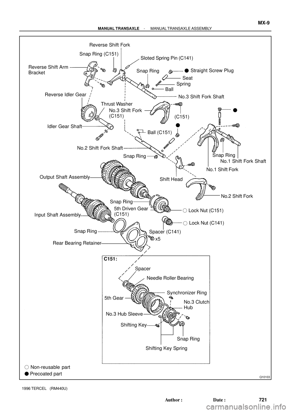
Q10103
Reverse Shift Arm
BracketReverse Shift Fork
Snap RingSnap Ring
Thrust Washer Reverse Idler Gear
Idler Gear Shaft
Ball (C151)Straight Screw Plug
�
BallSpringSeat
�
No.3 Shift Fork
(C151)�
No.2 Shift Fork Shaft
Output Shaft Assembly
Shift HeadNo.1 Shift Fork Shaft
No.1 Shift Fork
No.2 Shift Fork
Lock Nut (C141)
�
5th Driven Gear
(C151)
x5
Spacer Snap Ring
Rear Bearing Retainer
Needle Roller Bearing
5th GearSynchronizer Ring
No.3 Hub Sleeve
Shifting Key
� Non-reusable part
� Precoated partNo.3 Clutch
Hub
Snap Ring
Shifting Key SpringLock Nut (C151) �
Input Shaft AssemblySnap Ring
Spacer (C141)
No.3 Shift Fork Shaft Snap Ring (C151)
Snap RingSloted Spring Pin (C141)
(C151)
C151:
- MANUAL TRANSAXLEMANUAL TRANSAXLE ASSEMBLY
MX-9
721 Author�: Date�:
1996 TERCEL (RM440U)
Page 757 of 1202

Z13623
RPMidle
AT5867Drain plug Filler plug
MT0613
Filler Hole
Fluid Level
0 - 5 mm
e
Z15674
Adjusting Nut
Outer Cable Rubber Boot
Cable Stopper0 - 1 mm
BE1485
8 423
5 761
9 AX-4
- AUTOMATIC TRANSAXLE (A132L)AUTOMATIC TRANSAXLE SYSTEM (A132L)
1996 TERCEL (RM440U)
(4) Start the engine and shift the selector into all posi-
tions from the P position through the L position and
then shift it into the P position.
(5) With the engine idling, check the fluid level. Add the
fluid up to the COOL level on the dipstick.
(6) Check the fluid level at the normal operating tem-
perature 70 - 80 °C (158 - 176 °F) and add as nec-
essary.
NOTICE:
Do not overfill.
(d) If necessary, replace the differential fluid.
(1) Using a hexagon wrench, remove the drain plug
and drain the fluid.
(2) Using a hexagon wrench, install the drain plug se-
curely.
(3) Remove the filler plug.
(4) Add new fluid until it begins to run out of the filler
hole.
Fluid type: ATF D-ll or DEXRON®lll (DEXRON®ll)
Capacity: 1.4 liters (1.5 US qts, 1.2 lmp.qts)
(e) Check the differential fluid level.
Remove the filler plug and check the differential fluid lev-
el.
(f) Inspect and adjust the throttle cable.
(1) Depress the accelerator pedal all the way and
check that the throttle valve opens fully.
HINT:
If the throttle valve does not open fully, adjust the accelerator
link.
(2) Fully depress the accelerator.
(3) Loosen the adjustment nuts.
(4) Adjust the outer cable so that the distance between
the end of the boot and the stopper on the cable is
the standard.
Standard boot and cable stopper distance:
0 - 1 mm (0 - 0.04 in.)
(5) Tighten the adjusting nuts.
(6) Recheck the adjustment.
(g) Inspect the park/neutral position switch.
(1) Remove the park/neutral position switch
(See page AX-15).

(c)
(a)
P21132
(2)(1)(b)
(a)
P21130
P21029
CO-4
- COOLINGWATER PUMP
1996 TERCEL (RM440U)
REMOVAL
1. DRAIN ENGINE COOLANT
2. REMOVE GENERATOR
3. REMOVE INTAKE MANIFOLD STAY
(a) Di")