Page 602 of 1202

P21775
H
P21097
SST
CO0766
Clearance
Lock
Plate
O-Ring
- COOLINGRADIATOR
CO-21
1996 TERCEL (RM440U)
(b) Check the lock plate height (H) after completing the caulk-
ing.
Plate height: 7.75 - 8.25 mm (0.305 - 0.325 in.)
If not within the specified height, adjust the stopper bolt of the
handle again and perform the caulking again.
6. INSPECT FOR WATER LEAKS
(a) Tighten the drain plug.
(b) Plug the inlet and outlet pipes of the radiator with SST.
SST 09230-01010
(c) Using a radiator cap tester, apply pressure to the radiator.
Test pressure: 177 kPa (1.8 kgf/cm
2, 26 psi)
(d) Inspect for leaks.
HINT:
On radiators with resin tanks, there is a clearance between the
tank and lock plate where a minute amount of air will remain,
giving the appearance of an air leak when the radiator is sub-
merged in water. Therefore, before performing the water leak
test, first move radiator around in the water until all air bubbles
disappear.
7. PAINT LOCK PLATES
HINT:
If the water leak test checks out okay, allow the radiator to com-
pletely dry and then paint the lock plates.
Page 609 of 1202
CO0I9-04
P20884
CO-28
- COOLINGELECTRIC COOLING FAN
1996 TERCEL (RM440U)
REMOVAL
1. REMOVE NO.1 COOLING FAN
(a) Remove the engine under covers.
(b) Drain the engine coolant.
(c) Remove the air cleaner inlet.
(d) Remove the reservoir tank assembly.
(e) Remove the No.1 cooling fan.
(1) Disconnect the upper radiator hose from the radia-
tor.
(2) Disconnect the cooling fan connector.
(3) Remove the 2 bolts and cooling fan.
Torque: 7.0 N´m (70 kgf´cm, 61 in.´lbf)
2. REMOVE NO.2 COOLING FAN
(a) Disconnect the cooling fan connector.
(b) Remove the 3 bolts and cooling fan.
Torque: 7.0 N´m (70 kgf´cm, 61 in.´lbf)
Page 623 of 1202
LU08D-05
P20907
EM9278
EM9755
P20160
- LUBRICATIONOIL PUMP
LU-7
1996 TERCEL (RM440U)
REMOVAL
HINT:
When repairing the oil pump, the oil pan and strainer should be
removed and cleaned.
1. REMOVE HOOD
2. REMOVE OIL DIPSTICK
3. DRAIN ENGINE OIL
4. REMOVE TIMING BELT (See page EM-12)
5. SUSPEND ENGINE WITH ENGINE SLING DEVICE
6. REMOVE CRANKSHAFT TIMING PULLEY(See page
EM-12)
7. w/ A/C:
REMOVE A/C COMPRESSOR AND MOUNTING
BRACKET
(a) Disconnect the compressor connector.
(b) Remove the 4 compressor mounting bolts.
HINT:
Put a side compressor, and suspend it.
(c) Remove the 4 bolts and compressor mounting
bracket.
8. DISCONNECT FRONT EXHAUST PIPE
(a) Remove the 2 bolts and the 2 compresson springs.
(b) Disconnect the exhaust pipe.
Page 717 of 1202

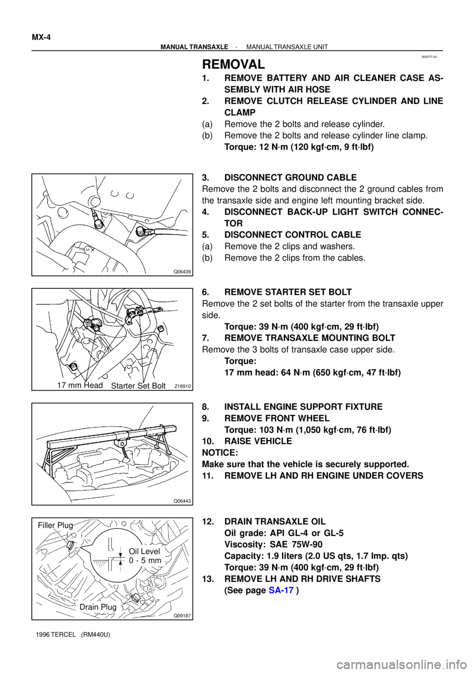
MX07F-04
Q06439
Z1891017 mm Head
Starter Set Bolt
Q06443
Q09187
Filler Plug
Oil Level
0 - 5 mm
Drain Plug MX-4
- MANUAL TRANSAXLEMANUAL TRANSAXLE UNIT
1996 TERCEL (RM440U)
REMOVAL
1. REMOVE BATTERY AND AIR CLEANER CASE AS-
SEMBLY WITH AIR HOSE
2. REMOVE CLUTCH RELEASE CYLINDER AND LINE
CLAMP
(a) Remove the 2 bolts and release cylinder.
(b) Remove the 2 bolts and release cylinder line clamp.
Torque: 12 N´m (120 kgf´cm, 9 ft´lbf)
3. DISCONNECT GROUND CABLE
Remove the 2 bolts and disconnect the 2 ground cables from
the transaxle side and engine left mounting bracket side.
4. DISCONNECT BACK-UP LIGHT SWITCH CONNEC-
TOR
5. DISCONNECT CONTROL CABLE
(a) Remove the 2 clips and washers.
(b) Remove the 2 clips from the cables.
6. REMOVE STARTER SET BOLT
Remove the 2 set bolts of the starter from the transaxle upper
side.
Torque: 39 N´m (400 kgf´cm, 29 ft´lbf)
7. REMOVE TRANSAXLE MOUNTING BOLT
Remove the 3 bolts of transaxle case upper side.
Torque:
17 mm head: 64 N´m (650 kgf´cm, 47 ft´lbf)
8. INSTALL ENGINE SUPPORT FIXTURE
9. REMOVE FRONT WHEEL
Torque: 103 N´m (1,050 kgf´cm, 76 ft´lbf)
10. RAISE VEHICLE
NOTICE:
Make sure that the vehicle is securely supported.
11. REMOVE LH AND RH ENGINE UNDER COVERS
12. DRAIN TRANSAXLE OIL
Oil grade: API GL-4 or GL-5
Viscosity: SAE 75W-90
Capacity: 1.9 liters (2.0 US qts, 1.7 Imp. qts)
Torque: 39 N´m (400 kgf´cm, 29 ft´lbf)
13. REMOVE LH AND RH DRIVE SHAFTS
(See page SA-17)
Page 721 of 1202
Z18912
Oil Receiver Pipe
Straight Screw Plug (C141)
�
Slotted Spring Pin (C151)
�Outer Race
Plate Washer Reverse Restrict Pin (C151)
Oil Receiver Pipe
x13 Transmission Case
� Lock Ball Assembly (C151)
�
Back-Up Light Switch
Lock Bolt
Breather Plug
Shift and Select Lever
Shaft Assembly
Selecting Bellcrank Assembly
�Oil Seal
x9
Transmission Case
Cover (C141) Drain Plug
� Non-reusable part
� Precoated partTransmission Case
Cover (C151)
x9
Gasket �Gasket
Filler Plug� �
Straight Screw Plug �Straight Screw Plug (C141)
�Gasket MX-8
- MANUAL TRANSAXLEMANUAL TRANSAXLE ASSEMBLY
720 Author�: Date�:
1996 TERCEL (RM440U)
Page 765 of 1202

Q02558
AX0RJ-02
Q04924
Z15675
A
B
C
AT4869
A
B
C
D
A
BC
D AX-12
- AUTOMATIC TRANSAXLE (A132L)VALVE BODY ASSEMBLY
764 Author�: Date�:
1996 TERCEL (RM440U)
VALVE BODY ASSEMBLY
ON-VEHICLE REPAIR
1. DRAIN TRANSAXLE FLUID
Using a hexagon wrench, remove the drain plug and drain the
fluid into the suitable container.
Torque: 49 N´m (500 kgf´cm, 36 ft´lbf)
2. REMOVE OIL PAN AND GASKET
NOTICE:
Some fluid will remain in the oil pan. Remove the oil pan
bolts, and carefully remove the oil pan assembly. Discard
the gasket.
Torque: 4.9 N´m (50 kgf´cm, 43 in.´lbf)
3. EXAMINE PARTICLES IN PAN
Remove the magnets and use then to collect any steel chips.
Look at the chips on the magnet carefully to anticipate what
type of wear you will find in the transaxle.
Steel (magnetic) ...... bearing, gear and plate wear
Brass (non-magnetic) ..... bushing wear
4. REMOVE OIL STRAINER
Remove the 3 bolts and the oil strainer.
NOTICE:
Be careful as some oil will come out of the strainer.
Torque: 10 N´m (100 kgf´cm, 7 ft´lbf)
5. REMOVE OIL PIPES
(a) Remove the 2 bolts and pipe bracket.
Torque: 10 N´m (100 kgf´cm, 7 ft´lbf)
(b) Pry up the both pipe ends with a large screwdriver and re-
move the 4 pipes.
NOTICE:
Be careful not to bend or damage the pipes.
Page 799 of 1202

AT3320
AX0RX-01
Q06911
Z15036
20 (0.79)
12 (0.47)25 (0.98)
20 (0.79)
AT3329
AX-16
- AUTOMATIC TRANSAXLE (A242L)VALVE BODY ASSEMBLY
798 Author�: Date�:
1996 TERCEL (RM440U)
VALVE BODY ASSEMBLY
ON-VEHICLE REPAIR
1. DRAIN ATF
Remove the drain plug and drain the ATF into the suitable con-
tainer.
Torque: 17 N´m (175 kgf´cm, 13 ft´lbf)
2. REMOVE OIL PAN AND GASKET
NOTICE:
Some fluid will remain in the oil pan. Remove the oil pan
bolts and carefully remove the oil pan assembly. Discard
the gasket.
Torque: 4.9 N´m (50 kgf´cm, 43 in.´lbf)
3. EXAMINE PARTICLES IN PAN
Remove the magnets and use then to collect any steel chips.
Look at the chips on the magnet carefully to anticipate what
type of wear you will find in the transaxle.
Steel (magnetic) ...... bearing, gear and plate wear
Brass (non-magnetic) ..... bushing wear
4. REMOVE OIL STRAINER AND APPLY PIPE BRACKET
(a) Remove the 3 bolts and oil strainer.
NOTICE:
Be careful as some oil will come out of the strainer.
Torque: 10 N´m (100 kgf´cm, 7 ft´lbf)
(b) Remove the 2 bolts and apply pipe bracket.
Torque: 10 N´m (100 kgf´cm, 7 ft´lbf)
5. REMOVE OIL PIPES
(a) Remove the clamp bolt.
(b) Pry up the both pipe ends with a large screwdriver and re-
move the 4 pipes.
NOTICE:
Be careful not to bend or damage the pipes.
Page 835 of 1202

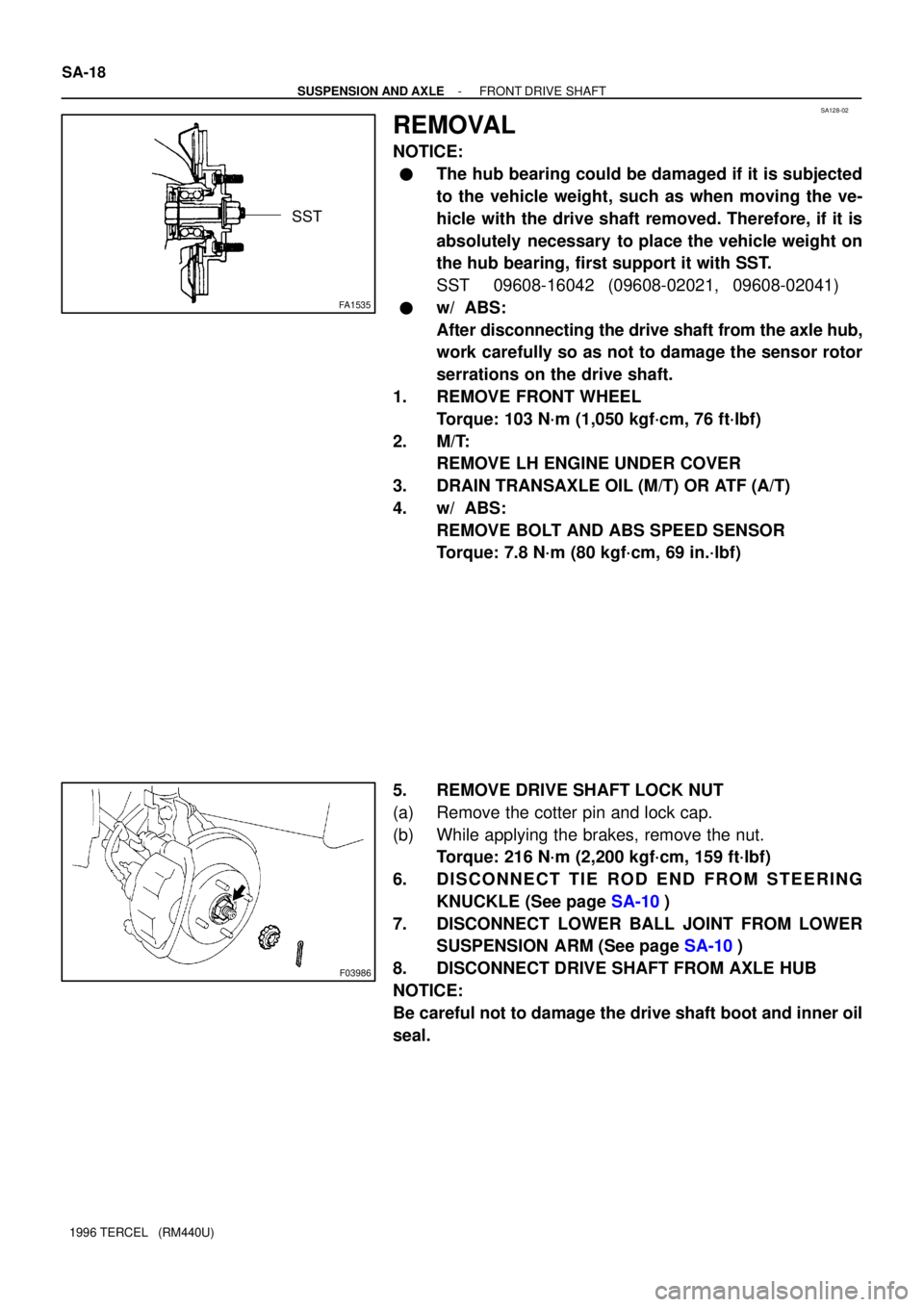
SA128-02
FA1535
SST
F03986
SA-18
- SUSPENSION AND AXLEFRONT DRIVE SHAFT
1996 TERCEL (RM440U)
REMOVAL
NOTICE:
�The hub bearing could be damaged if it is subjected
to the vehicle weight, such as when moving the ve-
hicle with the drive shaft removed. Therefore, if it is
absolutely necessary to place the vehicle weight on
the hub bearing, first support it with SST.
SST 09608-16042 (09608-02021, 09608-02041)
�w/ ABS:
After disconnecting the drive shaft from the axle hub,
work carefully so as not to damage the sensor rotor
serrations on the drive shaft.
1. REMOVE FRONT WHEEL
Torque: 103 N´m (1,050 kgf´cm, 76 ft´lbf)
2. M/T:
REMOVE LH ENGINE UNDER COVER
3. DRAIN TRANSAXLE OIL (M/T) OR ATF (A/T)
4. w/ ABS:
REMOVE BOLT AND ABS SPEED SENSOR
Torque: 7.8 N´m (80 kgf´cm, 69 in.´lbf)
5. REMOVE DRIVE SHAFT LOCK NUT
(a) Remove the cotter pin and lock cap.
(b) While applying the brakes, remove the nut.
Torque: 216 N´m (2,200 kgf´cm, 159 ft´lbf)
6. DISCONNECT TIE ROD END FROM STEERING
KNUCKLE (See page SA-10)
7. DISCONNECT LOWER BALL JOINT FROM LOWER
SUSPENSION ARM (See page SA-10)
8. DISCONNECT DRIVE SHAFT FROM AXLE HUB
NOTICE:
Be careful not to damage the drive shaft boot and inner oil
seal.